

Service and Parts Manual
Directional Valve Group
ECO 80
www.danfoss.com
Service and Parts Manual
Directional Valve Group ECO 80
Revision history Table of revisions
Date Changed Rev
December 2019 First edition 0101
2 | © Danfoss | December 2019 AX327462277301en-000101

Service and Parts Manual
Directional Valve Group ECO 80
Contents
Function
Safety.................................................................................................................................................................................................... 4
Sectional view....................................................................................................................................................................................5
Installation
Identification and oil flow direction for standard assembled ECO 80 LS.....................................................................6
Installation and plug orientation................................................................................................................................................7
Connections pump side and max flow setting......................................................................................................................8
Installation of lever...........................................................................................................................................................................9
Main spool assembly installation.............................................................................................................................................10
Service parts
EVP, pump side module...............................................................................................................................................................11
EVPX, electrical LS unloading valve.........................................................................................................................................13
EVB, basic module..........................................................................................................................................................................14
PVLP shock and PVLA suction valves......................................................................................................................................16
EVO, end plate.................................................................................................................................................................................18
EVBS spools...................................................................................................................................................................................... 19
EVM, mechanical actuation........................................................................................................................................................21
EVC, cover for mechanical actuation...................................................................................................................................... 22
EVOS, open spool through action............................................................................................................................................23
EVOS, open spool mechanical actuation...............................................................................................................................24
EVME, spring center/detent....................................................................................................................................................... 25
EVME through action....................................................................................................................................................................25
EVME, micro switch NO................................................................................................................................................................26
EVH, hydraulic actuation............................................................................................................................................................. 27
EVHC, proportional electrical control..................................................................................................................................... 28
EVHCO, ON/OFF..............................................................................................................................................................................29
EVPN, pneumatic actuator..........................................................................................................................................................30
EVPN, electrical pneumatic actuator.......................................................................................................................................31
EVT, assembly kit............................................................................................................................................................................32
Set of seals........................................................................................................................................................................................33
©
Danfoss | December 2019 AX327462277301en-000101 | 3
Service and Parts Manual
Directional Valve Group ECO 80
Function
Safety
It is the customer's responsibility to decide on the required degree of safety for the system. All marks and
all types of directional control and proportional valves can fail and cause serious damage. It is therefore
important to analyze all aspects of the application. Proportional valves are used in many different
operating conditions and applications; therefore the manufacturer of the application is responsible for
making the final selection of the products and assuring that all performance, safety and warning
requirements of the application are met.
Cost-free repairs, as mentioned in Danfoss General Conditions of Sale, are carried out only at Danfoss or
at service shops authorized by Danfoss.
4 | © Danfoss | December 2019 AX327462277301en-000101
Service and Parts Manual
Directional Valve Group ECO 80
Function
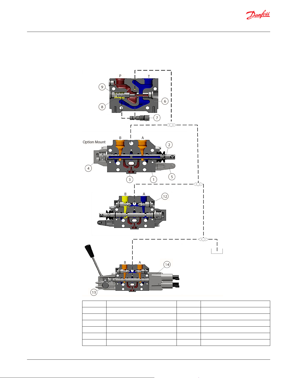
ECO 80 LS sectional view
1 Workstation EVB 8 Unloader spool
2 Spool EVBS 9 Unloader spool spring
3 Check valve 10 LS Shuttle
4 Spring center EVME 11 Load sensing
5 Actuator EVOS 12 Shock valve
6 Pump Inlet EVP 13 Spring center (EH) EVM
7 Load sense relief 14 Electric Actuator
©
Danfoss | December 2019 AX327462277301en-000101 | 5
EVB
Low Body
B
A
B
A
EVB
Medium Body
EVHC
EVP
EVS
EVM
EVH
B
A
B
A
A
B
EVB
Low Body
EVB
Medium Body
EVP
EVOS
EVS
XXX
XXX
XXX
XXX
XXX
XXX
XXX
C
C
EVHCO
EVPN Electro pneumatic
EVPN
EVC
ECO
ECO
Service and Parts Manual
Directional Valve Group ECO 80
Installation
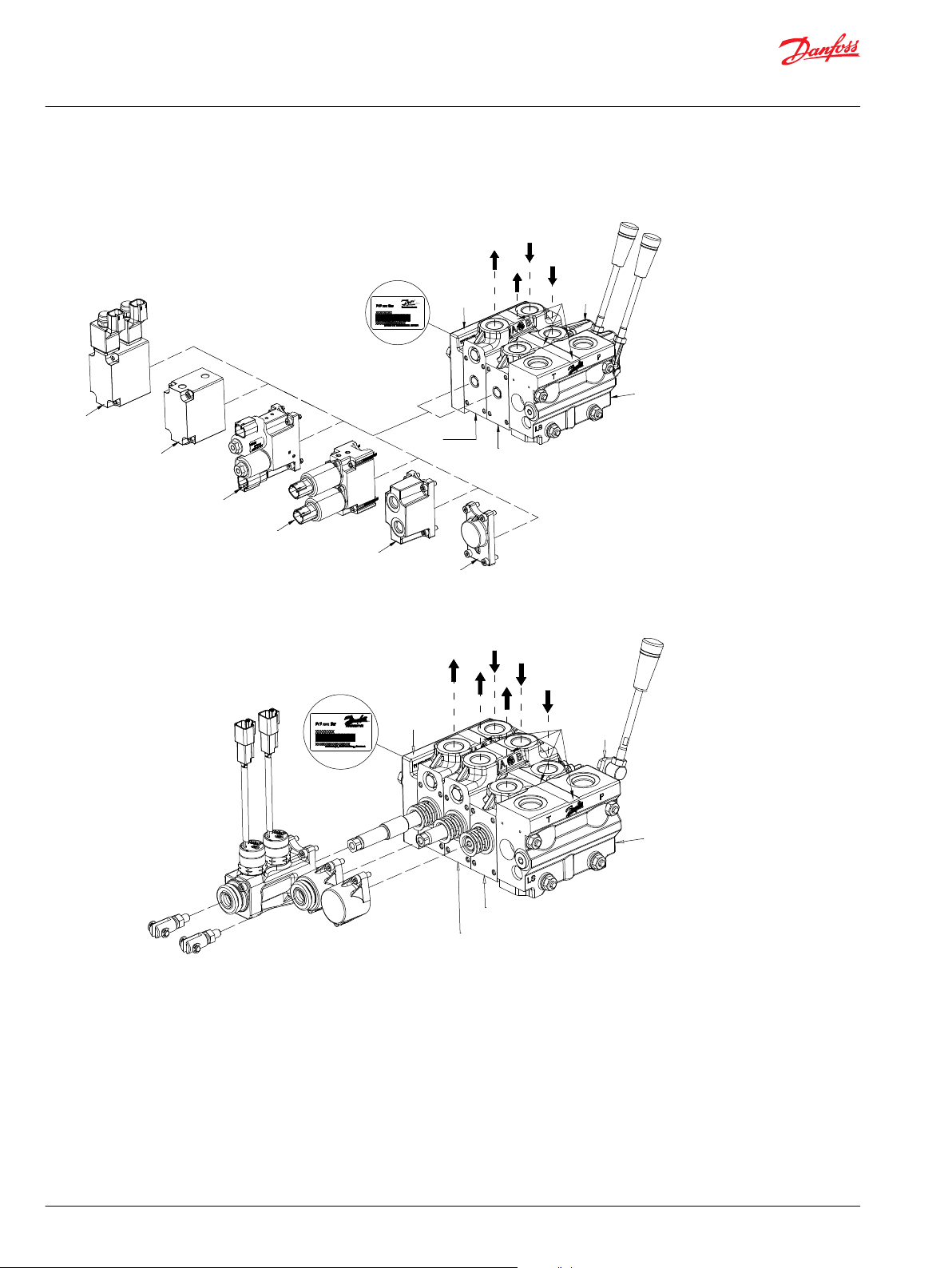
Identification and oil flow direction for standard assembled ECO 80 LS
C: Label with ECO 80 number, week and year of installation and series number.
6 | © Danfoss | December 2019 AX327462277301en-000101
L
*210[8.27]
*120[4.7]
*210[8.27]
*120[4.7]
98[3.86]
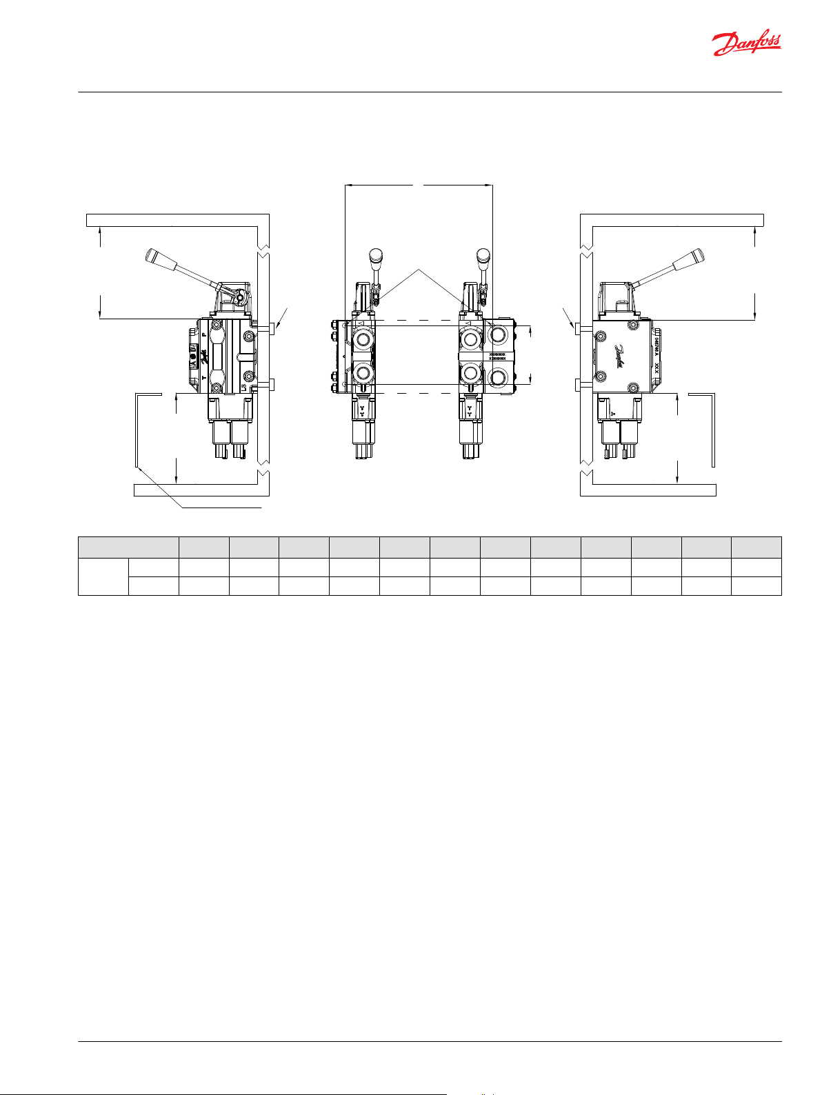
In particularly exposed applications, protection in the form of
screening of the electrical actuator is recommended
4x M8x1.25
EVP: Max. 40 Nm
EVO: Max. 20 Nm
Service and Parts Manual
Directional Valve Group ECO 80
Installation
ECO 80 installation and plug orientation
No. of EVB 1 2 3 4 5 6 7 8 9 10 11 12
L mm 65 105 145 185 225 265 305 345 385 425 465 505
[in] 2.56 4.13 5.71 7.28 8.86 10.43 12.01 13.58 15.16 16.73 18.31 19.88
©
Danfoss | December 2019 AX327462277301en-000101 | 7
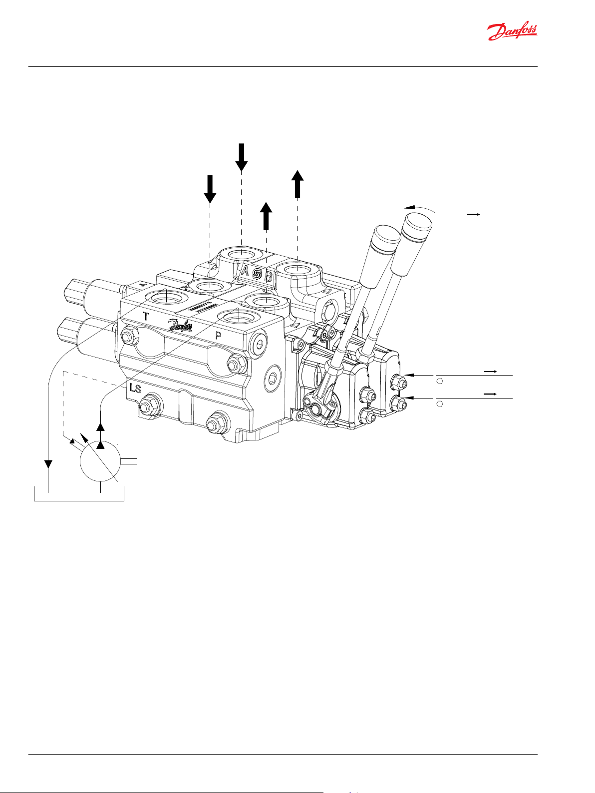
Flow P B
B
A
B
A
Max. flow: P A
6±1Nm[53±9lbf-in]
Max. flow: P B
6±1Nm[53±9lbf-in]
Service and Parts Manual
Directional Valve Group ECO 80
Installation
ECO 80 connections pump side and max flow setting
8 | © Danfoss | December 2019 AX327462277301en-000101
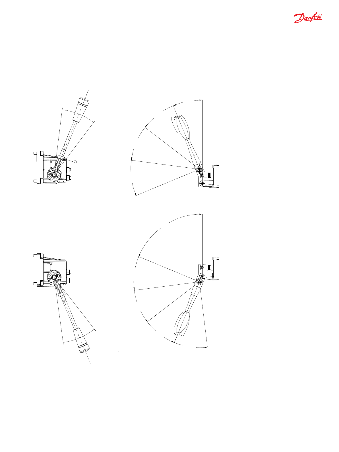
22.5°
22.5°
8±1Nm
22.5°
22.5°
52.5 °
22.5 °
82.5 °
112.5 °
67.5 °
97.5 °
127.5 °
157.5 °
187.5 °
Service and Parts Manual
Directional Valve Group ECO 80
Installation
ECO 80 installation of lever
Remember to screw the lever all the way in.
©
Danfoss | December 2019 AX327462277301en-000101 | 9
EVBS, MECHANICAL FLOW CONTROL SPOOLS,THROUGH ACTING
13mm HEX
8-10Nm
EVBS, MECHANICAL FLOW CONTROL SPOOLS,FEMALE EXTENSION
EVBS, MECHANICAL FLOW CONTROL SPOOLS,DETENT 03/02 POSITION
EVBS, ELECTRICAL FLOW CONTROL SPOOLS
EVBS, MECHANICAL FLOW CONTROL SPOOLS,MICRO SWITCH
8-10Nm
8-10Nm
6 mm
8-10 Nm
8-10Nm
8-10Nm
8-10Nm
11 mm
8-10 Nm
Service and Parts Manual
Directional Valve Group ECO 80
Installation
ECO 80 main spool assembly installation
Standard main spool assembly
10 | © Danfoss | December 2019 AX327462277301en-000101
7/8"
29-35Nm
7/8"
25-27Nm
3/4"
6-7Nm
OPEN CENTER
SAE PLUG HEX 1/4"(18-20Nm)
BSP PLUG HEX 6mm(29-35Nm)
13) CLOSED CENTER
SAE PLUG HEX 1/4"(18-20Nm)
BSP PLUG HEX 6MM(29-35Nm)
8 mm
22-26 Nm
6mm
29-35Nm
3/4"
18-20 Nm
5 mm
12-14 Nm
3/16"
4-5 Nm
ACCESS TO
RELIEF VALVE
RELIEF VALVE
4MM HEX
360° = 100 BAR
(CLOCKWISE)
1
2
3
4
5
11
10
3
4
7
12
9
6)Closed Center
8)Open Center
Service and Parts Manual
Directional Valve Group ECO 80
Service parts
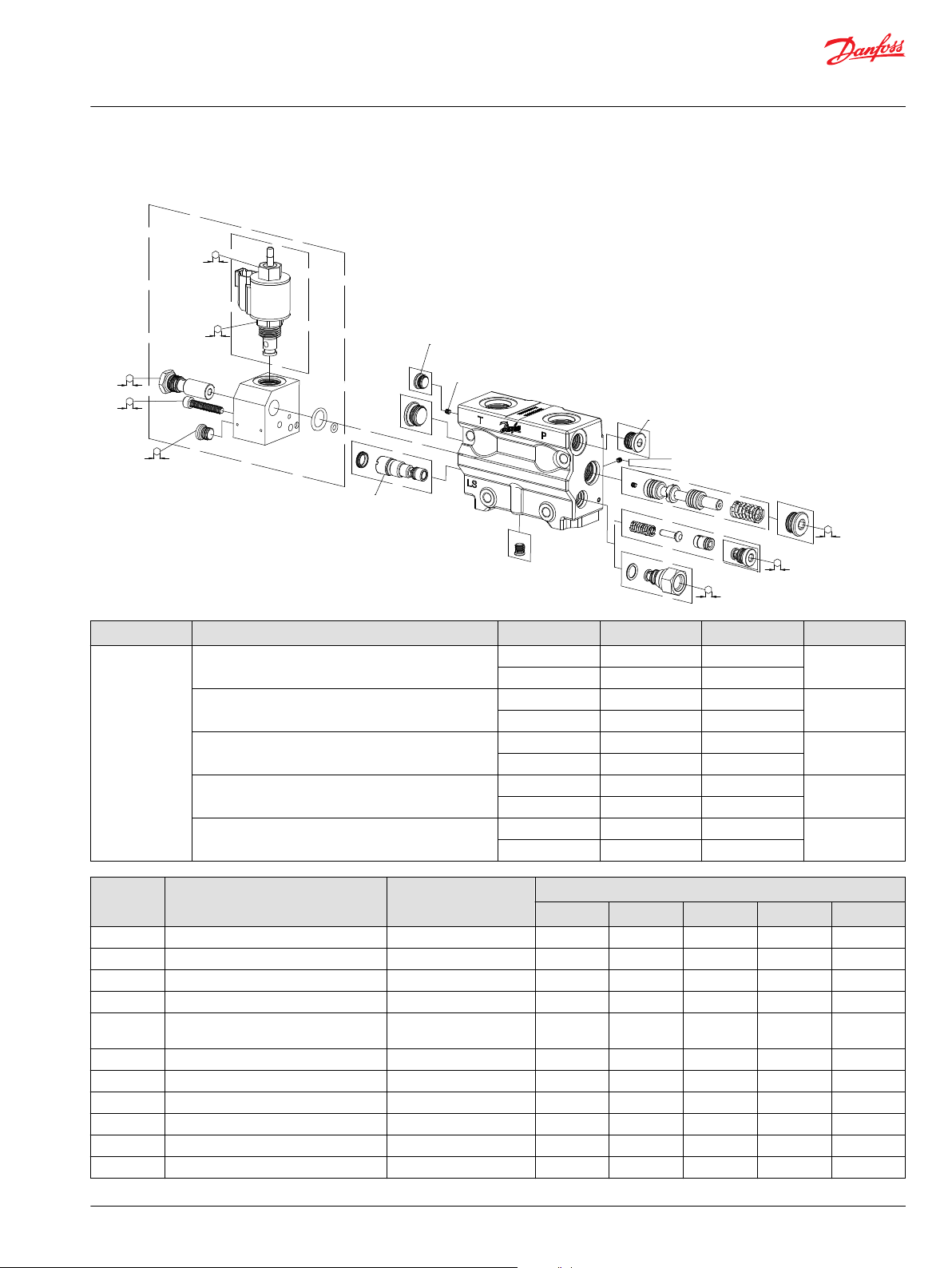
ECO 80 EVP, pump side module
Type Description Code number P-port T-port* Letter
EVP Open center 11173005 G1/2” G1/2” A
11172981 7/18-14 7/18-14
Closed center 11173006 G1/2” G1/2” B
11173002 7/18-14 7/18-14
Open center with pilot supply 11172996 G1/2” G1/2” C
11173010 7/18-14 7/18-14
Closed center with pilot supply 11172997 G1/2” G1/2” D
11173011 7/18-14 7/18-14
Open center with pilot supply and facilities for EVPX 11173023 G1/2” G1/2” E
11173000 7/18-14 7/18-14
Item Description Code number Letter
1 EVPX housing incl. EVPX See section EVPX - - - - 2 EVPX coil See section EVPX - - - - 3 Plug - 2 2 2 2 2
4 Plug - 2 2 2 2 2
5 Relief valve incl. sealed plastic adjusting
6 Orifice for closed center EVP (Ø0,8 x M6) - - 1 - 1 7 Inlet compensator assembly - 1 1 1 1 1
8 Plug for open center EVP (Pipe M6 x 1) - 1 - 1 - 1
9 Plug - - - 1 1 1
10 Pilot supply - - - 1 1 1
11 Plug for external pilot oil supply - 1 1 - - -
©
screw
- 1 1 1 1 1
Danfoss | December 2019 AX327462277301en-000101 | 11
A B C D E

Service and Parts Manual
Directional Valve Group ECO 80
Service parts
Item Description Code number Letter
A B C D E
12 Plug - 1 1 1 1 1
13 Plug for closed center EVP (Pipe M6 x 1) - - 1 - 1 *
Conversion kit open to closed – and
closed to open – center (Including item
3, 6, 8 and 13)
11177668 - - - - -
12 | © Danfoss | December 2019 AX327462277301en-000101

7/8"
25-27Nm
3/4"
6-7Nm
5MM
12-14Nm
3/16"
4-5Nm
ACCESS TO
RELIEF VALVE
1
2
3/4”
18-20 Nm
Service and Parts Manual
Directional Valve Group ECO 80
Service parts
ECO 80 EVPX, electrical LS unloading valve
EVPX
Description Code number
Normally open: LS pressure relieved with no signal to EVPX – 12 V 11172430
Normally open: LS pressure relieved with no signal to EVPX - 24 V 11172429
©
Danfoss | December 2019 AX327462277301en-000101 | 13

7/8" HEX
20-23Nm
2
1
PLVP
PLVA
Cavity-Plug
13mm HEX
29-35Nm
PLVP
PLVA
Cavity-Plug
13mm HEX
29-35Nm
8mm HEX
29-35Nm
8mm HEX
29-35Nm
7/8" HEX
20-23Nm
4
5
6
2
3
Service and Parts Manual
Directional Valve Group ECO 80
Service parts
ECO 80 EVB, basic module
Low body, no facilities for PVLP/PVLA
Medium body, with facilities for PVLP/PVLA
14 | © Danfoss | December 2019 AX327462277301en-000101

Service and Parts Manual
Directional Valve Group ECO 80
Service parts
Mechanical and electrical EVB
Type Description Code
EVB
Mechanical
EVB Electrical Low body without facilities for PVLP/PVLA 11168506 G1/2” G1/2” C
Item Description Code number Letter
1 Low body EVB See above 1 - 1 2 Check valve assembly - 1 1 1 1
3 High body EVB See above - 1 - 1
4 PVLA valve assembly See page (PVLP/PVLA) - - - 5 PVLP, shock and suction valve assembly See page (PVLP/PVLA) - - - 6 Anti-cavitation plug See page (PVLP/PVLA) - - - -
Low body without facilities for PVLP/PVLA 11168505 G1/2” G1/2” A
Medium body with facilities for PVLP/PVLA 11168503 G1/2” G1/2” B
Medium body with facilities for PVLP/PVLA 11168509 G1/2” G1/2” D
number
11168504 7/18-14 7/18-14
11168502 7/18-14 7/18-14
11168507 7/18-14 7/18-14
11168508 7/18-14 7/18-14
P-port T-port* Letter
A B C D
©
Danfoss | December 2019 AX327462277301en-000101 | 15

35±3 Nm
[310±27 lbf·in]
13 [0.50]
35±3 Nm
[310±27 lbf·in]
13 [0.50]
1
2
Service and Parts Manual
Directional Valve Group ECO 80
Service parts
ECO 80 PVLP shock and PVLA suction valves
PVLP/PVLA
16 | © Danfoss | December 2019 AX327462277301en-000101

Service and Parts Manual
Directional Valve Group ECO 80
Service parts
Type Part number
PVLA 157B2001
PVLP 157B2032
157B2050
157B2063
157B2080
157B2100
157B2125
157B2140
157B2150
157B2160
157B2175
157B2190
157B2210
157B2230
157B2240
157B2250
157B2265
157B2280
157B2300
157B2320
Adjustable PVLP 11006594 (121-250 bar [1755-3626 psi])
11006596 (251-285 bar [3640-4134 psi])
Cavity plug 11177714
©
Danfoss | December 2019 AX327462277301en-000101 | 17

3
2
1
3/16”
12-13 Nm
Service and Parts Manual
Directional Valve Group ECO 80
Service parts
ECO 80 EVO, end plate
Type Description Code number LX-port Letter
EVO End plate without LX-connection 11191585 - A
End plate with LX-connection 11191583 1/8 BSP B
11191582 7/16-20
End plate with Pneumatic port 11191584 1/8 BSP C
Item Description Code number Letter
1 EVO End Plate See above 1 1 1
2 Plug for LX port - - 1 3 Plug for pneumatic port - - 1 1
A B C
New EVO end plates released October 2018. See PIB (link) for details.
18 | © Danfoss | December 2019 AX327462277301en-000101

EVBS, MECHANICAL FLOW CONTROL SPOOLS,THROUGH ACTING
13mm HEX
8-10Nm
EVBS, MECHANICAL FLOW CONTROL SPOOLS,FEMALE EXTENSION
EVBS, MECHANICAL FLOW CONTROL SPOOLS,DETENT 03/02 POSITION
EVBS, ELECTRICAL FLOW CONTROL SPOOLS
EVBS, MECHANICAL FLOW CONTROL SPOOLS,MICRO SWITCH
8-10Nm
8-10Nm
6 mm
8-10 Nm
8-10Nm
8-10Nm
8-10Nm
11 mm
8-10 Nm
Service and Parts Manual
Directional Valve Group ECO 80
Service parts
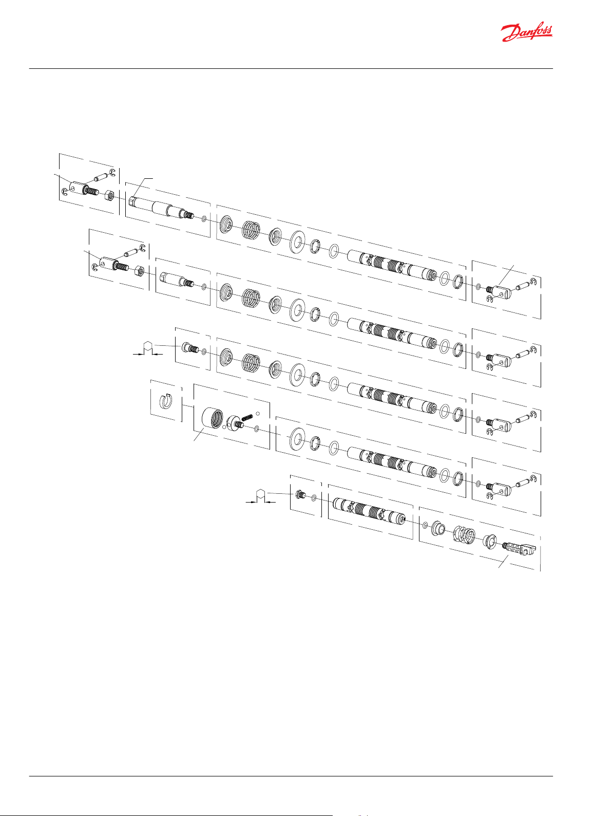
ECO 80 EVBS spools
Type Description Letter
EVBS Mechanical flow control spool, female extension and micro switch A
Mechanical flow control spool, female extension and through acting B
Mechanical flow control spool, female extension and detent 03/02 position C
Mechanical flow control spool, female extension D
Electrical flow control spool E
Item Description Code number Letter
1 Female extension 050548 1 1 - - 2 Screw including O-ring Ø 6.0 x 1.5 - 1 - - - 3 Main spool assembly - 1 1 1 - 4 Female extension 11169581 1 1 1 1 5 Screw incl. O-ring Ø 6.0 x 1.5 - - 1 - - -
A B C D E
©
Danfoss | December 2019 AX327462277301en-000101 | 19

Service and Parts Manual
Directional Valve Group ECO 80
Service parts
Item Description Code number Letter
A B C D E
6 Screw incl. O-ring Ø 6.0 x 1.5 - - - 1 - 7 Main spool assembly without spring and spring
stop
8 Detent kit 11177713 - - - 1 9 Plug incl. O-ring Ø 6.0 x 1.5 - - - - - 1
10 Main spool - - - - - 1
11 Tension rod incl. spring, spring stop and O-ring Ø
6.0 x 1.5
For EVBS spool part numbers, see ECO 80 Technical Information.
- - - 1 - -
- - - - - 1
20 | © Danfoss | December 2019 AX327462277301en-000101

1
2
3
3
3
3
4
3 mm
1.5-3.5 Nm
13 mm
7-9 Nm
10 mm
5-7 Nm
3 mm
4 mm
9-10 Nm
Service and Parts Manual
Directional Valve Group ECO 80
Service parts
ECO 80 EVM, mechanical actuation
Type Description Code number Letter
EVM EVM actuator 11119157 A
EVM actuator with lever 11167001 B
EVM actuator with adjustment screws 11145204 C
EVM actuator with adjustment screws and lever 11167002 D
Item Description Code number Letter
1 EVM - 1 1 1 1
2 Lever with handle and base 11107587 - 1 - 1
3 Screw M5 x 16 (12.9) - 4 4 4 4
4 Profile O-ring - 1 1 1 1
A B C D
©
Danfoss | December 2019 AX327462277301en-000101 | 21

2
1
4 mm
9-10 Nm
Service and Parts Manual
Directional Valve Group ECO 80
Service parts
ECO 80 EVC, cover for mechanical actuation
Type Description Code number
EVC Cover for mechanical activation 11171318
Item Description
1 Screw M5 x 16 (12.9)
2 O-ring Ø 20.35 x 1.78
22 | © Danfoss | December 2019 AX327462277301en-000101

1
4 mm
9-10 Nm
Service and Parts Manual
Directional Valve Group ECO 80
Service parts
ECO 80 EVOS, open spool through action
Type Description Code number
EVOS EVOS80LS-Actuator-Thru 11175233
Item Description
1 Screw M5 x 16 (12.9)
©
Danfoss | December 2019 AX327462277301en-000101 | 23

1
2
3
3
3
3
1
4
3
3
3
3
4 mm
9-10 Nm
4 mm
9-10 Nm
13 mm
9-10 Nm
13 mm
9-10 Nm
Service and Parts Manual
Directional Valve Group ECO 80
Service parts
ECO 80 EVOS, open spool mechanical actuation
Type Description Code number
EVOS EVOS80LS-Actuator-Mech 047768
EVOS80LS-Actuator-Mech with lever 11175314
EVOS80LS-Actuator-Mech with robust lever 11227308
Item Description Code number
1 Housing incl. screws 2 Lever with handle and base 11170923
24 | © Danfoss | December 2019 AX327462277301en-000101

4 mm
9-10 Nm
1
4 mm
9-10 Nm
Service and Parts Manual
Directional Valve Group ECO 80
Service parts
Item Description Code number
3 Screw M5 x 16 (12.9) 4 Robust lever with handle and base 11194826
ECO 80 EVME, spring center/detent
Type Description Code number
EVME Spring centering, detent 03/02 position 11169579
ECO 80 EVME, through action
Type Description Code number
EVME Through action 11169580
©
Danfoss | December 2019 AX327462277301en-000101 | 25

2
1
4 mm
9-10 Nm
1”
25-27 Nm
4 mm
4-5 Nm
Service and Parts Manual
Directional Valve Group ECO 80
Service parts
Item Description
1 Screw M5 x 16 (12.9)
ECO 80 EVME, micro switch NO
Type Description Code number
EVME Micro switch NO 11170841
Item Description Code number
1 Rubber boot 11177717
2 Micro switch 11178486
26 | © Danfoss | December 2019 AX327462277301en-000101

2
1
4 mm
9-10 Nm
Service and Parts Manual
Directional Valve Group ECO 80
Service parts
ECO 80 EVH, hydraulic actuation
Type Description Code number Letter
EVH Cover for hydraulic actuation – 9/16-18 UNF 11169487 A
Cover for hydraulic actuation – G1/4 11169486 B
Item Description Code number Letter
A B
1 Screw M5 x 16 (12.9) - 4 4
2 Set of seals - 1 1
©
Danfoss | December 2019 AX327462277301en-000101 | 27

1
2
3
4 mm
7 ± 0.5 Nm
3 mm
5 ± 0.5 Nm
Service and Parts Manual
Directional Valve Group ECO 80
Service parts
ECO 80 EVHC, proportional electrical control
Type Description Code number Letter
EVHC DEUTSCH connector 12 V 11162297 A
DEUTSCH connector 24 V 11162298 B
Item Description Code number Letter
A B C D
1 Screw M5 x 16 (12.9) - 4 4 4 4
2 Proportional Coil 12 V, DEUTSCH connector incl. 4
3 Set of seals - 1 1 1 1
screws
Proportional Coil 24 V, DEUTSCH connector incl. 4
screws
11061233 2 - 2 -
11061234 - 2 - 2
28 | © Danfoss | December 2019 AX327462277301en-000101

1
2
3
4
4 mm
7 ± 0.5 Nm
13 mm
2 ± 0.5 Nm
Service and Parts Manual
Directional Valve Group ECO 80
Service parts
ECO 80 EVHCO, ON/OFF
Type Description Code number Letter
EVHCO DEUTSCH connector 12 V 11186922 A
DEUTSCH connector 24 V 11186911 B
Item Description Code number Letter
A B
1 Housing - 1 1
2 Screw M5 x 16 - 4 4
3 Coil DEUTSCH connector 12 V 11198786 2 -
Coil DEUTSCH connector 24 V 11198787 - 2
4 Set of seals 11198712 1 1
This is a new version of the EVHCO ON/OFF actuator released June 2019. See PIB PV2019-419 for details.
©
Danfoss | December 2019 AX327462277301en-000101 | 29

3
1
2
2
4 mm
7 ± 0.5 Nm
Service and Parts Manual
Directional Valve Group ECO 80
Service parts
ECO 80 EVPN, pneumatic actuator
Type Description Code number Letter
EVPN Pneumatic actuator module 11198492 A
Item Description Code number Letter
1 EVPN - 1
2 Plug for Air Inlet supply 1/8 BSP – ISO1179 N-NBR90 - 2
3 Screw M5 x 65 - 4
* Set of seals 11230331 1
A
30 | © Danfoss | December 2019 AX327462277301en-000101

1
2
3
4
3
5
17 mm
1-1.5 Nm
4 mm
7 ± 0.5 Nm
Service and Parts Manual
Directional Valve Group ECO 80
Service parts
ECO 80 EVPN, electrical pneumatic actuator
Type Description Code number Letter
EVPN Electric pneumatic actuator module – DEUTSCH connector 12 V 11193722 A
Electric pneumatic actuator module – DEUTSCH connector 24 V 11193723 B
Electric pneumatic actuator module – AMP connector 24 V 11194345 C
Item Description Code number Letter
A B C
1 EVPN - 1 1 1
2 Screw M5 x 65 - 4 4 4
3+4+5 Coil DEUTSCH connector 12 V 11234123 2 - -
* Set of seals 11230331 1 1 1
Coil DEUTSCH connector 24 V 11234124 - 2 Coil AMP connector 24 V 11142988 - - 2
©
Danfoss | December 2019 AX327462277301en-000101 | 31

1
1
1
1
1
1
18-20 Nm
13 mm [0.50 in]
18-20 Nm
13 mm [0.50 in]
Service and Parts Manual
Directional Valve Group ECO 80
Service parts
ECO 80 EVT, assembly kit
Item Description Code number
1 Set of seals for ECO 80 wit 7 work sections: EVB 80 11178489
32 | © Danfoss | December 2019 AX327462277301en-000101

Service and Parts Manual
Directional Valve Group ECO 80
Service parts
ECO 80 set of seals
Type Code number Letter
EVP Module 11177669 A
EVP with facilities for EVPX Module 11177670 B
EVB, Low & High body Module 11177712 C
EVT For ECO 80 wit 7 work sections: EVB8011178489 D
EVBS, Mechanical spools Module 11177715 E
EVM Module 11177716 F
EVHC/O and EVH Module 11177718 G
EVC Module 11187093 H
Description Letter
A B C D E F G H
O-ring Ø 11.0 x 2.0 1 1 - - - - - O-ring Ø 15.3 x 2.4 (NBR D-90) 2 2 - - - - - O-ring Ø 11.89 x 1.98 (NBR D-90) 2 1 - - - - - O-ring Ø 1.98 x 11.89 (NBR D-90) - 1 - - - - - Plug 7/16-20 UNF-2A - 1 - - - - - O-ring Ø 16.36 x 2.21 (NBR D-90) - - 1 - - - - O-ring Ø 15.6 x 1.78 - - 2 - - - - O-ring Ø 7.65 x 1.78 (NBR D-90) - - 2 - - - - O-ring Ø 2.5 x 11 (NBR D-90) - - - 24 - - - O-ring Ø 2 x 5 (NBR D-70) - 1 - 16 - - - O-ring Ø 2.62 x 15.54 (Viton) - 1 - 16 - - - O-ring Ø 2.62 x 15.54 (NBR D-70) - - - - 2 - - Backup - - - - 2 - - Seal nut - - - - - 2 - Screw M5 x 16 (12.9) - - - - - 4 4 4
Profile O-ring - - - - - 1 - Profile ring - - - - - - 2 Profile ring - - - - - - 2 O-ring Ø 20.35 x 1.78 (NBR D-70) - - - - - - 1 O-ring Ø 41 x 1.78 (NBR D-70) - - - - - - - 1
O-ring Ø 3.68 x 1.78 (NBR D-70) - - - - - - - 1
©
Danfoss | December 2019 AX327462277301en-000101 | 33

Danfoss
Power Solutions GmbH & Co. OHG
Krokamp 35
D-24539 Neumünster, Germany
Phone: +49 4321 871 0
Danfoss
Power Solutions ApS
Nordborgvej 81
DK-6430 Nordborg, Denmark
Phone: +45 7488 2222
Danfoss
Power Solutions (US) Company
2800 East 13th Street
Ames, IA 50010, USA
Phone: +1 515 239 6000
Danfoss
Power Solutions Trading
(Shanghai) Co., Ltd.
Building #22, No. 1000 Jin Hai Rd
Jin Qiao, Pudong New District
Shanghai, China 201206
Phone: +86 21 2080 6201
Products we offer:
Hydro-Gear
www.hydro-gear.com
Daikin-Sauer-Danfoss
www.daikin-sauer-danfoss.com
DCV directional control
•
valves
Electric converters
•
Electric machines
•
Electric motors
•
Gear motors
•
Gear pumps
•
Hydrostatic motors
•
Hydrostatic pumps
•
Orbital motors
•
PLUS+1® controllers
•
PLUS+1® displays
•
PLUS+1® joysticks and
•
pedals
PLUS+1® operator
•
interfaces
PLUS+1® sensors
•
PLUS+1® software
•
PLUS+1® software services,
•
support and training
Position controls and
•
sensors
PVG proportional valves
•
Steering components and
•
systems
Telematics
•
Danfoss Power Solutions is a global manufacturer and supplier of high-quality hydraulic and
electric components. We specialize in providing state-of-the-art technology and solutions
that excel in the harsh operating conditions of the mobile off-highway market as well as the
marine sector. Building on our extensive applications expertise, we work closely with you to
ensure exceptional performance for a broad range of applications. We help you and other
customers around the world speed up system development, reduce costs and bring vehicles
and vessels to market faster.
Danfoss Power Solutions – your strongest partner in mobile hydraulics and mobile
electrification.
Go to www.danfoss.com for further product information.
We offer you expert worldwide support for ensuring the best possible solutions for
outstanding performance. And with an extensive network of Global Service Partners, we also
provide you with comprehensive global service for all of our components.
Local address:
Danfoss can accept no responsibility for possible errors in catalogues, brochures and other printed material. Danfoss reserves the right to alter its products without notice. This also applies to products
already on order provided that such alterations can be made without subsequent changes being necessary in specifications already agreed.
All trademarks in this material are property of the respective companies. Danfoss and the Danfoss logotype are trademarks of Danfoss A/S. All rights reserved.
©
Danfoss | December 2019 AX327462277301en-000101
 Loading...