

Page 1

Technical Information
Directional Control Valve
ECO 80
www.danfoss.com
Page 2

Technical Information
ECO 80 Directional Control Valve
Revision history Table of revisions
Date Changed Rev
September 2020 Document entirely re-worked - new version of document 0301
February 2020 Updated document number to match online reference 0201
August 2019 Updated code numbers for EVO end plates 0103
March 2017 Updated schematic 0102
October 2016 First edition 0101
2 | © Danfoss | September 2020 BC199786485316en-000301
Page 3

Technical Information
ECO 80 Directional Control Valve
Contents
General information
General description......................................................................................................................................................................... 5
ECO modules......................................................................................................................................................................................5
Safety in systems...............................................................................................................................................................................5
ECO 80 LS sectional view............................................................................................................................................................... 6
Mechanical acting ECO 80
ECO 80 mechanical modules overview.................................................................................................................................... 8
EVP inlet modules - mechanical acting
Open center EVP.............................................................................................................................................................................10
Closed center EVP.......................................................................................................................................................................... 12
EVB basic modules - mechanical acting
EVB low body...................................................................................................................................................................................15
EVB medium body......................................................................................................................................................................... 16
EVB basic modules accessories
PVLP shock/anti-cavitation valve............................................................................................................................................. 18
PVLA suction valve and cavity plug.........................................................................................................................................20
EVBS mechanical flow control spools
EVBS fluid flow characteristics - Theoretical performance..............................................................................................22
EVBS - female extension.............................................................................................................................................................. 24
EVBS - female extension and through acting...................................................................................................................... 25
EVBS - female extension and Detent 03 and 02 position spool out or in..................................................................26
EVBS - female extension and Micro Switch...........................................................................................................................27
ECO 80 mechanical - actuation
EVOS - open spool through action.......................................................................................................................................... 29
EVOS - open spool mechanical actuation............................................................................................................................. 31
EVME - open spool centering.................................................................................................................................................... 33
EVME - micro switch NO.............................................................................................................................................................. 35
EVOS x EVME combination overview......................................................................................................................................36
EVO - end plate
EVO......................................................................................................................................................................................................37
EVO with LX-connection..............................................................................................................................................................37
Electrical actuated ECO 80
ECO 80 electrical modules overview.......................................................................................................................................39
EVP inlet modules - electrical
Open center EVP with PPRV....................................................................................................................................................... 41
Closed center EVP with PPRV.....................................................................................................................................................44
EVP inlet module accessories
EVPX electrical LS pressure unloading valve........................................................................................................................46
Plug for external pilot oil supply.............................................................................................................................................. 47
EVB basic modules - electrical actuation
EVB low body...................................................................................................................................................................................49
EVB medium body......................................................................................................................................................................... 50
EVB basic modules accessories
PVLP shock/anti-cavitation valve............................................................................................................................................. 51
PVLA suction valve and cavity plug.........................................................................................................................................52
EVBS electrical flow control spools
EVBS fluid flow characteristics - Theoretical performance..............................................................................................54
EVBS - electrical flow control spool......................................................................................................................................... 55
EVBS - electrical flow control spool with soft spring for EVHCO...................................................................................56
EVBS - EVPN spool..........................................................................................................................................................................56
ECO 80 electrical - actuation
EVM mechanical actuation.........................................................................................................................................................57
©
Danfoss | September 2020 BC199786485316en-000301 | 3
Page 4

Technical Information
ECO 80 Directional Control Valve
Contents
EVM without adjustment screws........................................................................................................................................ 57
EVM with adjustment screws............................................................................................................................................... 57
EVM dimensions, torque, and part numbers..................................................................................................................57
EVC - cover for mechanical actuation.....................................................................................................................................59
EVH - hydraulic actuation............................................................................................................................................................60
EVHC - electrical actuation..........................................................................................................................................................61
EVHCO - Low current on/off electrical actuation................................................................................................................63
EVPN - pneumatic actuation......................................................................................................................................................64
EVPN - electrical pneumatic action..........................................................................................................................................65
EVO - end plate
EVO with pneumatic port............................................................................................................................................................68
EVT - assembly kit for both mechanical and electrical acting
ECO 80 dimension overview
4 | © Danfoss | September 2020 BC199786485316en-000301
Page 5

Technical Information
ECO 80 Directional Control Valve
General information
General description
The ECO 80 LS is a hydraulic load sensing proportional valve group designed to give maximum flexibility
in design and build concept. The ECO 80 LS is designed as a load sensing directional control valve which
will lead to increased machine performance, higher efficiency, reduced cooling requirements and fuel
saving compared to conventional directional control valves.
ECO 80 LS features
PVG load-sensing proportional valves features and benefits summarized inb bullets below:
•
Load sensing directional control:
Proportional control of oil flow to a work function
‒
•
Modular build concept:
Up to 12 basic modules per ECO 80 LS valve group
‒
Different, interchangeable spool variants
‒
System pressure up to 280 bar
‒
Work port pressure up to 320 bar
‒
Compact design and installation
‒
ECO modules
EVP, pump side modules
•
Built-in pressure relief valve
•
Pressure gauge connection
•
Versions:
Open center version for systems with fixed displacement pumps
‒
Closed center version for systems with variable displacement pumps
‒
Integrated 25 bar pilot oil supply for hydraulic and electrohydraulic actuaqtion
‒
Versions prepared for electrical LS unloading valve
‒
EVB, basic modules
•
Interchangeable spools
•
Load holding check valve in channel P
•
Option for shock and suction valves for port A and B
Actuation modules
The basic module could be fitted with three main different actuation modules:
•
Mechanical
•
Electrical
•
Hydraulic
•
Pneumatic
Safety in systems
All makes and all types of control valves (incl. proportional valves) can fail, thus the necessary protection
against the serious consequences of function failure should always be built into the system. For each
application an assessment should be made for the consequences of pressure failure and uncontrolled or
blocked movements.
©
Danfoss | September 2020 BC199786485316en-000301 | 5
Page 6

W
Technical Information
ECO 80 Directional Control Valve
General information
Warning
All makes/brands and types of directional control valves – inclusive proportional valves – can fail and
cause serious damage. It is therefore important to analyze all aspects of the application.
Because the proportional valves are used in many different operation conditions and applications, the
manufacturer of the application is alone responsible for making the final selection of the products – and
assuring that all performance, safety and warning requirements of the application are met.
The process of choosing the control system – and safety levels – is governed by the machine directives
EN 13849 (Safety related requirements for control systems).
ECO 80 LS sectional view
6 | © Danfoss | September 2020 BC199786485316en-000301
Page 7

Technical Information
ECO 80 Directional Control Valve
General information
1 Work Section (EVB)
2 Spool (EVBS)
3 Check valve
4 Open spool centering (EVME)
5 Mechanical actuator (EVOS)
6 Inlet module (EVP)
7 Load sense relief valve
8 Unloader spool
9 Uloader spool spring
10 Mechanical actuator (EVM)
11 Electrical actuator (EVHC)
12 Shock valve (PVLP)
13 Shuttle disc
Option moutn only possible with EVOS/EVME configuration
©
Danfoss | September 2020 BC199786485316en-000301 | 7
Page 8

Technical Information
ECO 80 Directional Control Valve
Mechanical acting ECO 80
This section will only be about the mechanical acting modules of the ECO 80 portfolio. For information on
the electrical actuated modules of the ECO80 portfolio, see Electrical actuated ECO 80 on page 39.
ECO 80 mechanical modules overview
8 | © Danfoss | September 2020 BC199786485316en-000301
Page 9

[3.86]
98
[3.86]
98
[2.10]
53,4
[4.90]
124,5
[0.17]
4,3
Technical Information
ECO 80 Directional Control Valve
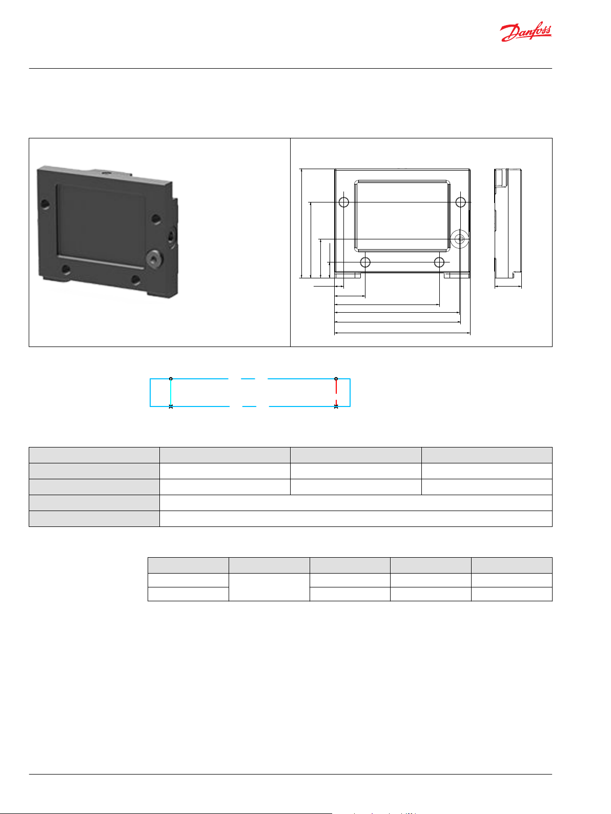
EVP inlet modules - mechanical acting
The ECO 80 EVP inlet modules, also referred to as pump side modules, act as an interface between the
ECO 80 directional valve group and the hydraulic pump and tank reservoir.
EVP Inlet module EVP Inlet module dimensions
Fixed displacement pump symbol Variable displacement pump symbol
The EVP inlet module variants are based on a generic platform with a selection of additional features,
enabling you to tailor the EVP to suit the demands of any hydraulic system:
•
Open center EVP (for fixed displacement pumps)
•
Closed center EVP (for variable displacement pumps)
©
Danfoss | September 2020 BC199786485316en-000301 | 9
Page 10

LS
T
P
M
Technical Information
ECO 80 Directional Control Valve
EVP inlet modules - mechanical acting
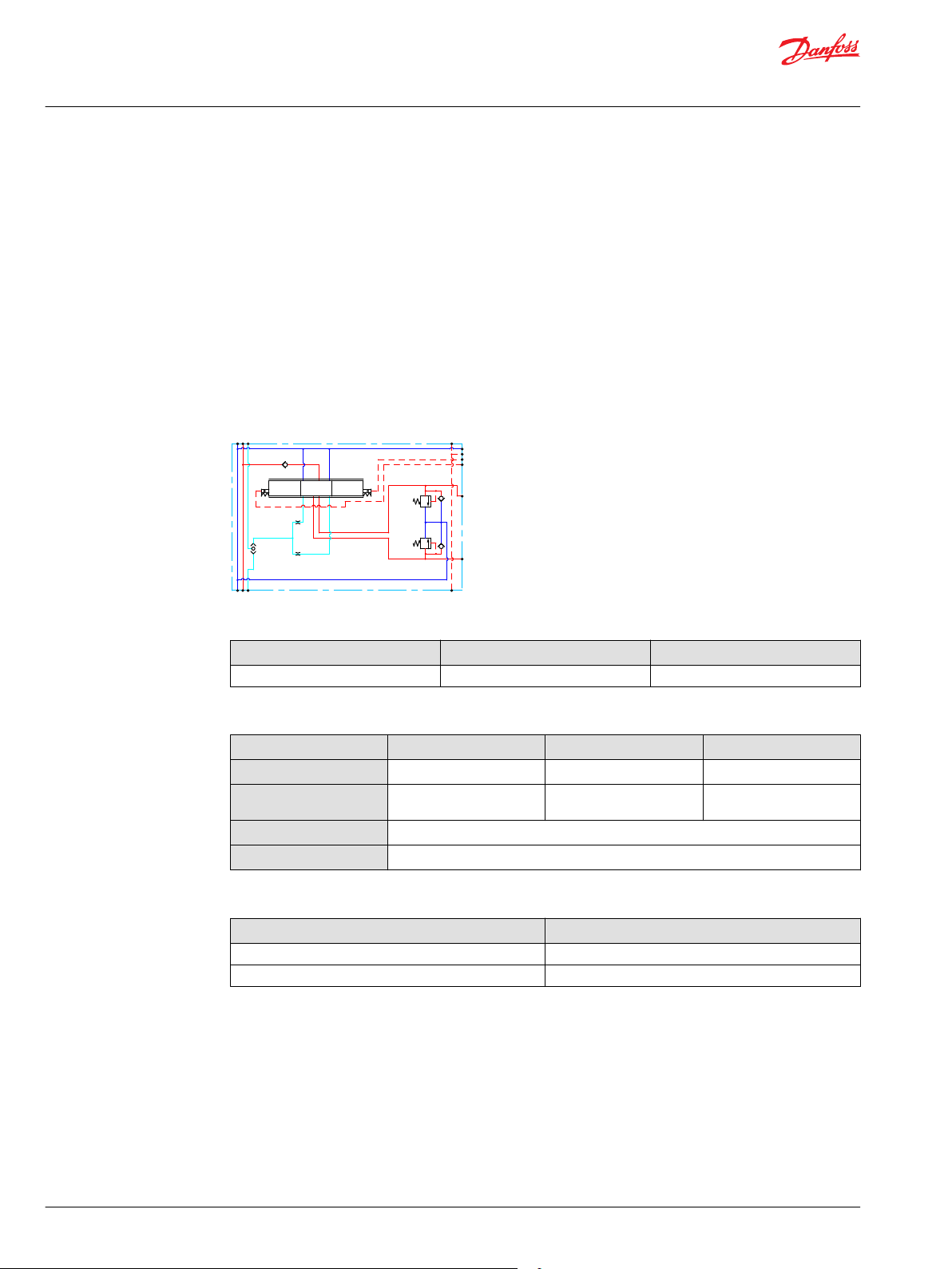
Open center EVP
The basic Open Center EVP inlet module is intended for use with fixed displacement pumps in
applications, where a valve group with mechanically controlled work sections is desired.
The Open Center EVP features:
•
Integrated LS pressure relief valve
•
Threaded ports for P/T/LS and M measuring gauge
Open center EVP schematic
Technical specification for EVP
Max. P-port continuous Max. T-port static/dynamic Max. rated flow
280 bar [4061 psi] 25/40 bar [365/580 psi] 100 l/min [26.4 US gal/min]
Technical specification
Parameter Minimum Recommended range Maximum
Fluid temperature
Fluid viscosity
Fluid cleanliness
Operating temperature
-30°C [-22°F] 30 to 60°C [86 to 140°F] 90°C [194°F]
4 mm2/s [39 SUS] 12 to 75 mm2/s [65 to 347 SUS] 460 mm2/s [2128 SUS]
23/19/16 (according to ISO 4406)
Ambient: -30 to 60°C [-22 to 140°F]
10 | © Danfoss | September 2020 BC199786485316en-000301
Page 11

20 40 60 80
[l/min]
[US gal/min]
4 8 12 16 20
300
250
200
150
100
50
0
Q
PP
4000
3000
2000
1000
0
0
[psi] [bar]
0
Q
10 30 50 70
50 bar
100 bar
150 bar
200 bar
250 bar
280 bar
24
90 100
Curves to inlet pressure x flow
20 40 60 80
[l/min]
[US gal/min]
4 8 12 16 20
20
16
12
8
4
0
Q
Δ PΔ P
240
160
80
0
0
[psi] [bar]
0
Q
100
24
24
320
Neutral flow pressure in EVP open center inlet
Technical Information
ECO 80 Directional Control Valve
EVP inlet modules - mechanical acting
Theoretical performance graphs
Pressure relief valve characteristics
Neutral by-pass pressure drop characteristics (open center)
Part numbers for Open Center EVP
Part numbers P-port T-port M-, LS-port Mounting
11173005
11172981
©
Danfoss | September 2020 BC199786485316en-000301 | 11
G 1/2 G 1/2 G 1/4 M8 x 1.25
7/8-14 UNF 7/8-14 UNF 9/16-18 UNF M8 x 1.25
Page 12

LS
T
P
M
Technical Information
ECO 80 Directional Control Valve
EVP inlet modules - mechanical acting
Closed center EVP
The basic Closed Center EVP inlet is intended for use with variable displacement pumps in applications
where a valve group with mechanically controlled work sections is desired.
The Closed Center EVP features:
•
Integrated LS pressure relief valve
•
Threaded ports for P/T/LS and M measuring gauge
Closed center EVP schematic
Technical specification for EVP
Max. P-port continuous Max. T-port static/dynamic Max. rated flow
280 bar [4061 psi] 25/40 bar [365/580 psi] 100 l/min [26.4 US gal/min]
Technical specification
Parameter Minimum Recommended range Maximum
Fluid temperature
Fluid viscosity
Fluid cleanliness
Operating temperature
-30°C [-22°F] 30 to 60°C [86 to 140°F] 90°C [194°F]
4 mm2/s [39 SUS] 12 to 75 mm2/s [65 to 347 SUS] 460 mm2/s [2128 SUS]
23/19/16 (according to ISO 4406)
Ambient: -30 to 60°C [-22 to 140°F]
12 | © Danfoss | September 2020 BC199786485316en-000301
Page 13

20 40 60 80
[l/min]
[US gal/min]
4 8 12 16 20
300
250
200
150
100
50
0
Q
PP
4000
3000
2000
1000
0
0
[psi] [bar]
0
Q
10 30 50 70
50 bar
100 bar
150 bar
200 bar
250 bar
280 bar
24
90 100
Curves to inlet pressure x flow
Technical Information
ECO 80 Directional Control Valve
EVP inlet modules - mechanical acting
Theoretical performance graphs
Pressure relief valve characteristics
Part numbers for Mechanical Acting Closed Center EVP
Part numbers P-port T-port M-, LS-port Mounting
11173006
11173002
G 1/2 G 1/2 G 1/4 M8 x 1.25
7/8-14 UNF 7/8-14 UNF 9/16-18 UNF M8 x 1.25
©
Danfoss | September 2020 BC199786485316en-000301 | 13
Page 14

[2.70]68.5
[1.70]43
[0.35]9
[1.57]40
[1.38]35
[0.79]
20
[0.20]5
[0.19]4.8
[4.80]122
[3.58]91
[1.08]
27.5
[0.31]
8
[3.72]94.5
[4.49]114
[0.19]4.7
[3.07]78
[1.69]43
[2.70]68.5
[0.35]9
[1.57]40
[1.38]35
[0.79]
20
[0.20]5
[2.42]61.5
[4.49]114
[0.31]8
[3.72]94.5
[1.08]27.5
[0.28]7
Technical Information
ECO 80 Directional Control Valve
EVB basic modules - mechanical acting
The ECO 80 EVB basic modules, also referred to as work sections, are the interface between the ECO 80
directional control valve and the work function such as a cylinder or a motor. The EVB comes in two main
variants – a low body and a medium body with shock/anti-cavitation valve facility (PVLP)
EVB low basic module EVB low basic module dimensions
EVB medium basic module EVB medium basic module dimensions
The EVB basic module variants are based on a generic platform with a selection of additional features,
enabling you to tailor the EVB to suit the demands of any hydraulic system:
•
EVB low body
•
EVB medium body
14 | © Danfoss | September 2020 BC199786485316en-000301
Page 15

A
B
1
0
2
Technical Information
ECO 80 Directional Control Valve
EVB basic modules - mechanical acting
EVB low body
The EVB low body is intended for controlling a work function where the function behavior in terms of
flow and pressures allows dependency on the load pressure of other functions used simultaneously. The
integrated load drop check valve prevents flow back from work ports influencing other functions.
The EVB low body features:
•
Integrated LS shuttle network
•
Load drop check valve
Schematic
Technical specification for A/B-port
Max. continuous pressure Max. intermittent pressure Max. rated flow
280 bar [4061 psi] 320 bar [4641 psi] 100 l/min [26.4 US gal/min]
Technical specification
Parameter Minimum Recommended range Maximum
Fluid temperature
Fluid viscosity
Fluid cleanliness
Operating temperature
-30°C [-22°F] 30 to 60°C [86 to 140°F] 90°C [194°F]
4 mm2/s [39 SUS] 12 to 75 mm2/s [65 to 347 SUS] 460 mm2/s [2128 SUS]
23/19/16 (according to ISO 4406)
Ambient: -30 to 60°C [-22 to 140°F]
Part numbers
Part numbers A/B-port
11168505
11168504
G 1/2
7/8-14 UNF
©
Danfoss | September 2020 BC199786485316en-000301 | 15
Page 16

A
B
1
0
2
Technical Information
ECO 80 Directional Control Valve
EVB basic modules - mechanical acting
EVB medium body
The EVB low body is intended for controlling a work function where the function behavior in terms of
flow and pressures allows dependency on the load pressure of other functions used simultaneously. The
integrated load drop check valve prevents flow back from work ports influencing other functions.
Compared to the EVB low body the medium body has the option of adding PVLP/PVLA to the work
section.
The EVB medium body features:
•
Integrated LS shuttle network
•
Load drop check valve
•
Shock/anti-cavitation valve and suction facility (PVLP/PVLA)
Schematic
Technical specification for A/B-port
Max. continuous pressure Max. intermittent pressure Max. rated flow
280 bar [4061 psi] 320 bar [4641 psi] 100 l/min [26.4 US gal/min]
Technical specification
Parameter Minimum Recommended range Maximum
Fluid temperature
Fluid viscosity
Fluid cleanliness
Operating temperature
-30°C [-22°F] 30 to 60°C [86 to 140°F] 90°C [194°F]
4 mm2/s [39 SUS] 12 to 75 mm2/s [65 to 347 SUS] 460 mm2/s [2128 SUS]
23/19/16 (according to ISO 4406)
Ambient: -30 to 60°C [-22 to 140°F]
Part numbers
Part number A/B-port
11168503
11168502
G 1/2
7/8-14 UNF
16 | © Danfoss | September 2020 BC199786485316en-000301
Page 17

Technical Information
ECO 80 Directional Control Valve
EVB basic modules accessories
The generic EVB module accessory platform include the PVLP shock and anti-cavitation valve and PVLA
suction valve.
•
PVLP Shock and Anti-cavitation valve
•
PVLA Suction valve
•
Cavity plug
©
Danfoss | September 2020 BC199786485316en-000301 | 17
Page 18

Port pressure
Technical Information
ECO 80 Directional Control Valve
EVB basic modules accessories
PVLP shock/anti-cavitation valve
The PVLP will relief a pressure peak to the internal tank galleries and will furthermore suck oil from the
tank to the work port to prevent cavitation. Pressure settings range 32-320 bar [460-4641 psi].
Features:
•
Shock valve
•
Anti-cavitation
•
Lifetime of 200,000 actuations
•
Optional fixed or adjustable
PVLP schematic
Technical specification
Parameter Minimum Recommended range Maximum
Fluid temperature
Fluid viscosity
Fluid cleanliness
Operating temperature
-30°C [-22°F] 30 to 60°C [86 to 140°F] 90°C [194°F]
4 mm2/s [39 SUS] 12 to 75 mm2/s [65 to 347 SUS] 460 mm2/s [2128 SUS]
23/19/16 (according to ISO 4406)
Ambient: -30 to 60°C [-22 to 140°F]
Part numbers for fixed PVLP
Part number Pressure setting in bar [psi]
157B2032 32 [460]
157B2050 50 [725]
157B2063 63 [914]
157B2080 80 [1160]
157B2100 100 [1450]
157B2125 125 [1813]
157B2140 140 [2031]
157B2150 150 [2175]
157B2160 160 [2320]
157B2175 175 [2538]
157B2190 190 [2755]
157B2210 210 [3045]
157B2230 230 [3335]
157B2240 240 [3480]
157B2250 250 [3625]
157B2265 265 [3845]
157B2280 280 [4061]
157B2300 300 [4351]
157B2320 320 [4641]
18 | © Danfoss | September 2020 BC199786485316en-000301
Page 19

Technical Information
ECO 80 Directional Control Valve
EVB basic modules accessories
Part numbers for adjustable PVLP
Part number Pressure setting in bar [psi]
11006594 121-250 [1755-3626]
11006595 251-285 [3640-4134]
©
Danfoss | September 2020 BC199786485316en-000301 | 19
Page 20

Port pressure
Technical Information
ECO 80 Directional Control Valve
EVB basic modules accessories
PVLA suction valve and cavity plug
The PVLA will suck oil from the tank to the work port to prevent cavitation by the 0.5 bar spring. The plug
will ensure that when using a single acting spool, all flow returning through the work port is led to tank.
PVLA schematic
Cavity plug schematic
Technical specification
Parameter Minimum Recommended range Maximum
Fluid temperature
Fluid viscosity
Fluid cleanliness
Operating temperature
-30°C [-22°F] 30 to 60°C [86 to 140°F] 90°C [194°F]
4 mm2/s [39 SUS] 12 to 75 mm2/s [65 to 347 SUS] 460 mm2/s [2128 SUS]
23/19/16 (according to ISO 4406)
Ambient: -30 to 60°C [-22 to 140°F]
Part numbers for PVLA and plug
PVLA Cavity plug
157B2001 11177714
20 | © Danfoss | September 2020 BC199786485316en-000301
Page 21

Technical Information
ECO 80 Directional Control Valve
EVBS mechanical flow control spools
The mechanical acting EVBS spools determine the flow out of the work section and are based on a
generic platform with a wide selection of additional features, enabling you to tailor the EVBS to suit the
demands of any hydraulic system and any function.
The mechanical acting EVBS spool comes in four different main variants:
•
EVBS Female Extension
•
EVBS Female Extension and through acting
•
EVBS Female Extension and Detent 03 position and 02 position spool out or in
•
EVBS Female Extension and Micro Switch
1
1
For 02 position detent spool out is necessary to use an accessory part number 11173406, see EVME, detent 02 position spool to A or
B
©
Danfoss | September 2020 BC199786485316en-000301 | 21
Page 22

BP
5
10
15
20
25
30
35
40
45
50
55
60
65
[l/min]
[US gal/min]
70
75
80
1
2
3
4
5
6
7
8
9
10
11
12
13
14
15
16
17
18
19
20
21
A
P
[mm]
<-Spool stroke->
5
43
[in]
0-0.04-0.08-0.12
-0.16-0.20
2
-0.24
1
0
-0.28-0.31-0.35
-0.39
A
E
C
D
B
85
90
95
100
22
23
24
25
26
0-1
-2
-3
-4
-5
0.39
0.350.310.28
0.240.20
0.16
0.120.080.04
0
[mm]
[in]
Flow
105
110
115
120
27
28
29
30
31
32
Spool types:
A = 8/min
B = 25 l/min
C = 40 l/min
D = 60 l/min
E = 80 l/min
F = 100 l/min*
F
Technical Information
ECO 80 Directional Control Valve
EVBS mechanical flow control spools
EVBS fluid flow characteristics - Theoretical performance
Oil flow as a function of spool travel
22 | © Danfoss | September 2020 BC199786485316en-000301
Page 23

40 80 120 160
[l/min]
[US gal/min]
8 16 24 32 40
50
40
30
20
10
0
600
400
200
0
0
[psi] [bar]
0
A
B
D
C
20 60 100 140
E
TA/B
A = Spool 8 l/min
B = Spool 25 l/min
C = Spool 40 l/min
D = Spool 60 l/min
E = Spool 80 l/min
F
F = Spool 100 l/min
Technical Information
ECO 80 Directional Control Valve
EVBS mechanical flow control spools
Pressure drop at maximum spool travel (A/B-T)
©
Danfoss | September 2020 BC199786485316en-000301 | 23
Page 24

20.7 [0.81]
171.5 [6.75]
33 [1.30]
A
PT T
B
A
PT T
B
A
PT T
B
Technical Information
ECO 80 Directional Control Valve
EVBS mechanical flow control spools
EVBS - female extension
EVBS Female Extension EVBS Female Extension dimensions mm [in]
Part numbers for EVBS Female Extension
Type Schematic Flow, l/min [US gal/min]
4-way, 3-position
Closed neutral position
8
[2.11]
11169728 11169733 11169737 11169741 11169745 11182571
25
[6.61]
40
[10.57]60[15.85]80[21.13]
100
[26.42]
4-way, 3-position
Throttled open neutral position
3-way, 3-position
Closed neutral position
11169725 11169730 11169735 11169739 11169743 11182572
11169729 11169734 11169738 11169742 11169746 -
24 | © Danfoss | September 2020 BC199786485316en-000301
Page 25

33 [1.3]171.5 [6.75]76.5 [3.0]
A
PT T
B
A
PT T
B
A
PT T
B
Technical Information
ECO 80 Directional Control Valve
EVBS mechanical flow control spools
EVBS - female extension and through acting
EVBS Female Extension and through acting EVBS Female Extension and through acting dimensions mm [in]
Part numbers for EVBS Female Extension
Type Schematic Flow, l/min [US gal/min]
4-way, 3-position
Closed neutral position
8
[2.11]
11170744 11170747 11170750 11170753 11170756 11187072
25
[6.61]
40
[10.57]60[15.85]80[21.13]
100
[26.42]
4-way, 3-position
Throttled open neutral position
3-way, 3-position
Closed neutral position
11170743 11170746 11170749 11170752 11170755 11187061
11170745 11170748 11170751 11170754 11170757 -
©
Danfoss | September 2020 BC199786485316en-000301 | 25
Page 26

Ø
16
Ø
33
[1.10]28
[0.90]
23
[5.55]141
Technical Information
ECO 80 Directional Control Valve
EVBS mechanical flow control spools
EVBS - female extension and Detent 03 and 02 position spool out or in
EVBS Female Extension and Detent EVBS Female Extension and Detent dimensions mm [in]
For 02 position detent spool out is necessary to use an accessory part number 11173406, see EVME,
detent 02 position spool to A or B
Part numbers for EVBS Female Extension
Type Schematic Flow, l/min [US gal/min]
4-way, 3-position
Closed neutral position
4-way, 3-position
Throttled open neutral position
3-way, 3-position
Closed neutral position
8
[2.11]
11170627 11170634 11170638 11170642 11170646 11182609
11170625 11170632 11170636 11170640 11170644 11182610
11170631 11170635 1117639 11170643 11170647 -
25
[6.61]
40
[10.57]60[15.85]80[21.13]
100
[26.42]
26 | © Danfoss | September 2020 BC199786485316en-000301
Page 27

33 [1.3]
171.5 [6.75]134.5 [5.3]
A
PT T
B
A
PT T
B
A
PT T
B
Technical Information
ECO 80 Directional Control Valve
EVBS mechanical flow control spools
EVBS - female extension and Micro Switch
EVBS Female Extension and Micro Switch EVBS Female Extension and Micro Switch dimensions mm [in]
Part numbers for EVBS Female Extension
Type Schematic Flow, l/min [US gal/min]
4-way, 3-position
Closed neutral position
8
[2.11]
11170264 11170268 11170272 11170276 11170280 11187073
25
[6.61]
40
[10.57]60[15.85]80[21.13]
100
[26.42]
4-way, 3-position
Throttled open neutral position
3-way, 3-position
Closed neutral position
11170262 11170266 11170270 11170274 11170278 11187074
11170265 11170269 11170273 11170277 11170281 -
©
Danfoss | September 2020 BC199786485316en-000301 | 27
Page 28

Technical Information
ECO 80 Directional Control Valve
ECO 80 mechanical - actuation
ECO80 Mechanical actuation can be done manually or mechanically
ECO80 mechanical actuation overview:
•
EVOS - Open spool through action
•
EVOS - Open spool mechanical actuation
•
EVME - Open spool centering
•
EVME - Micro switch NO
28 | © Danfoss | September 2020 BC199786485316en-000301
Page 29

9 [0.35]
[0.77]
19.6
[2.78]70.5
[1.55]39.4
Technical Information
ECO 80 Directional Control Valve
ECO 80 mechanical - actuation
EVOS - open spool through action
The EVOS open spool through action consists of an aluminum base with a rubber boot to protect the
spool, mounted on the end of the valve slice, the connection with application is a female extension
assembled on the main spool.
The valve is actuated by directly pulling or pushing the main spool inside the valve hence controlling the
flow. Actuating the spool fully will move all 5 mm and give full flow. The EVOS should be used with open
spool mechanical actuation and can be combined with any EVME, spring center, detent, through action
and micro switch.
EVOS through action EVOS through action dimensions mm [in]
Operating force for EVOS through action
Spool displacement Operating linear force
EVOS + EVME (Through Acting)
From neutral position 135 ± 5 [N]
Maximum spool travel 180 ± 5 [N]
EVOS through action function
©
Danfoss | September 2020 BC199786485316en-000301 | 29
Page 30

Technical Information
ECO 80 Directional Control Valve
ECO 80 mechanical - actuation
Part numbers for EVOS mechanical actuation
Description Part number
EVOS80LS Through action 11172533
30 | © Danfoss | September 2020 BC199786485316en-000301
Page 31

64 [2.52]
[4.50]114.4
[7.47]189.8
[1.54]39
125.6 [4.95]
[2.11]53.5
[8.50]215.7
[1.54]39
Technical Information
ECO 80 Directional Control Valve
ECO 80 mechanical - actuation
EVOS - open spool mechanical actuation
The EVOS mechanical actuation consists of an aluminum base with a lever and a rubber boot to protect
the spool, mounted on the end of the valve slice. When actuating the lever, the operator is directly
pulling or pushing on the main spool inside the valve hence controlling the flow.
The lever has a travel of 14° in either direction from neutral. Actuating the lever fully will move the spool
all 5 mm and give full flow. The lever can be mounted / removed without having to remove the EVOS
base.
The EVOS should be used with open spool mechanical actuation and can be combined with any EVME,
spring center, detent, through action and micro switch.
EVOS mechanical actuation Dimensions in mm [in]
EVOS mechanical actuation power lever Dimensions in mm [in]
©
Danfoss | September 2020 BC199786485316en-000301 | 31
Page 32

Technical Information
ECO 80 Directional Control Valve
ECO 80 mechanical - actuation
Operating torque for EVOS mechanical actuation
Spool displacement
From neutral position
Maximum spool travel
No control level position
Control lever range
Part numbers for EVOS mechanical actuation
Description Part number
EVOS80LS Mechanical Actuator 047768
EVOS80 Mechanical Actuator with lever 11175314
EVOS80 Mechanical Actuator with power lever 11227308
Accessories - Base handle black 11170923
Accessories - Base handle black power lever 11194826
Operating torque N·m
EVOS + EVME (sspring center, Micro Switch)
3.5 ± 0.2
4.5 ± 0.2
2 x 6
±14°
32 | © Danfoss | September 2020 BC199786485316en-000301
Page 33

[1.34]34
[2.70]68.5
[1.74]44.2
[2.70]68.5
[1.34]34
Technical Information
ECO 80 Directional Control Valve
ECO 80 mechanical - actuation
EVME - open spool centering
The EVME spring centering consists of an aluminum cover mounted on the end of the valve slice which
ensures the position of the spool in neutral positions and spool in/out. The EVME spring centering should
be used with spool option: Mechanical flow control spools, Female Extension. And can be combined with
any EVOS, Open spool actuators.
EVME spring centering Dimensions in mm [in]
EVME through action Dimensions mm [in]
©
Danfoss | September 2020 BC199786485316en-000301 | 33
Page 34

Technical Information
ECO 80 Directional Control Valve
ECO 80 mechanical - actuation
Detent positions
EVME, detent 03 position
The EVME detent 03 positions consists of an aluminum cover mounted on the end of the valve slice
which keep the position of the spool in neutral positions and spool in/out.
The EVME detent 03 positions should be used with spool option: Mechanical flow control spools, Female
Extension and Detent 03 position. And can be combined with any EVOS, Open spool actuators.
EVME, detent 02 position spool to A or B
The EVME detent 02 positions consists of an aluminum cover mounted on the end of the valve slice
which keep the position of the spool in neutral positions and spool out, position spool in is blocked.
The EVME detent 02 positions should be used with spool option: Mechanical flow control spools, Female
Extension and Detent 03 position with accessory part number 11173406. And can be combined with any
EVOS, Open spool actuators.
EVME, through action
The EVME through action consists of an aluminum cover with a rubber boot to protect the spool,
mounted on the end of the valve slice which ensures the position of the spool in neutral positions and
spool in/out.
The valve is actuated by directly pulling or pushing the main spool inside the valve hence controlling the
flow. Actuating the spool fully will move all 5 mm and give full flow. The EVME through action should be
used with spool option: Mechanical flow control spools, Female Extension and through acting. Can be
combined with any EVOS, Open spool actuators.
Part numbers for EVME Spring centering
Description Part number
EVME80LS-COVER 11169579
Accessory Detent 02 Position 11173406
EVME80LS Through action 11169580
34 | © Danfoss | September 2020 BC199786485316en-000301
Page 35

[3.51]89.1
[3.56]90.5
[4.14]105.2
[8.92]226.6
[1.54]39
Technical Information
ECO 80 Directional Control Valve
ECO 80 mechanical - actuation
EVME - micro switch NO
The EVME Micro Switch consists of an aluminum cover mounted on the end of the valve slice, which
enables by two micro switches know which side the spool is being stroked, in or out.
The micro switches can have contacts in the configuration normally open “NO”. The EVME Micro Switch
should be used with spool option: Mechanical flow control spools, Female Extension and Micro Switch.
And can be combined with any EVOS, Open spool actuators.
EVME Micro switch Dimensions mm [in]
Technical data for EVME Micro Switch
Parameter Voltage
12 V 24 V
Max. current 10 A
Resistance 0.010 Ω ± 15 %
Part numbers for EVME micro switch
Description Connector type Protection class Part number
EVME80LS Micro Switch DEUTSCH DT04-2P IP 67 11170841
©
Danfoss | September 2020 BC199786485316en-000301 | 35
Page 36

Technical Information
ECO 80 Directional Control Valve
ECO 80 mechanical - actuation
EVOS x EVME combination overview
Work port A Work port B
EVOS, Open spool mechanical actuation EVME, Open spool centering
Mechanical
actuator
EVME,
Open spool centering
EVOS,
Open spool mechanical
actuation
Cover,
Spring center and
detent
Cover through action x x x
Micro Switch x x x
Mechanical actuator x x x
Mechanical actuator
with lever/power
lever
Through action x x x
x x x
Mechanical
actuator with
lever/power lever
Through
action
Cover,
Spring
center and
detent
x x x
Cover
through
action
Micro
Switch
36 | © Danfoss | September 2020 BC199786485316en-000301
Page 37

[4.51]114.5
[3.74]95
[1.10]
28
[4.84]123
[0.94]
24
[3.90]99
[2.70]68.5
[0.55]14
[0.33]8.5
Technical Information
ECO 80 Directional Control Valve
EVO - end plate
The ECO80 EVO end plates close off the valve stack section by placing them at the end. Furthermore, the
end plate is ensuring Load Sense (LS) is relieved to tank pressure when the valve is not operated.
The EVO end plate variants are based on a generic platform with a selection of additional features,
enabling you to tailor the EVO to suit the demands of any hydraulic system.
The generic EVO end plate platform includes the following main variants:
•
EVO
•
EVO with LX-connection and pneumatic port
•
EVO with pneumatic port
EVO
The EVO end plate closes off the valve stack section by placing it at the end. Furthermore, the end plate is
ensuring Load Sense (LS) is relieved to tank pressure when the valve is not operated
EVO EVO dimensions mm [in]
Technical specification
Parameter Minimum Recommended range Maximum
Fluid temperature
Fluid viscosity
Fluid cleanliness
Operating temperature
EVO with LX-connection
©
Danfoss | September 2020 BC199786485316en-000301 | 37
Schematic
-30°C [-22°F] 30 to 60°C [86 to 140°F] 90°C [194°F]
4 mm2/s [39 SUS] 12 to 75 mm2/s [65 to 347 SUS] 460 mm2/s [2128 SUS]
23/19/16 (according to ISO 4406)
Ambient: -30 to 60°C [-22 to 140°F]
Part numbers for EVO end plate
Part number Description Mounting
11191585 EVO End plate M8
The EVO end plate closes off the valve stack section by placing it at the end. Furthermore, the end plate is
ensuring Load Sense (LS) is relieved to tank pressure when the valve is not operated. The LX port enables
Page 38
[4.51]114.5
[4.47]113.5
[3.74]95
[1.10]28
[4.84]123
[0.94]24
[1.38]35
[3.90]99
[2.70]68.5
[0.55]14
[0.33]8.5
Lx Pneumatic
Technical Information
ECO 80 Directional Control Valve
EVO - end plate
other remote valves to be connected onto the Load Sense shuttle network. The end plate also features a
blocked pneumatic port.
EVO with LX-connection Dimensions mm [in]
Schematic
Technical specification
Parameter Minimum Recommended range Maximum
Fluid temperature
Fluid viscosity
Fluid cleanliness
Operating temperature
-30°C [-22°F] 30 to 60°C [86 to 140°F] 90°C [194°F]
4 mm2/s [39 SUS] 12 to 75 mm2/s [65 to 347 SUS] 460 mm2/s [2128 SUS]
23/19/16 (according to ISO 4406)
Ambient: -30 to 60°C [-22 to 140°F]
Part numbers for EVO wioth LX-connection end plate
Part number Description LX port Pneumatic port Mounting
11191583 EVO End plate with
11191582 7/16-20 UNF G1/8-28 M8
LX connection
G1/8-28 G1/8-28 M8
38 | © Danfoss | September 2020 BC199786485316en-000301
Page 39

Technical Information
ECO 80 Directional Control Valve
Electrical actuated ECO 80
This section will only be about the electrical actuated modules of the ECO 80 portfolio. For information
on the mechanical acting modules of the ECO80 portfolio, see…
ECO 80 electrical modules overview
Electrical modules exploded view
©
Danfoss | September 2020 BC199786485316en-000301 | 39
Page 40

[2.10]53.4
[4.90]124.5
[3.72]94.5
[2.70]68.5
[0.33]8
[0.55]14
[2.17]55
[4.49]114
[5.34]135.6
[1.08]
27.5
[0.79]2
Technical Information
ECO 80 Directional Control Valve
EVP inlet modules - electrical
The ECO 80 EVP inlet modules, also referred to as pump side modules, act as an interface between the
ECO 80 directional valve group and the hydraulic pump and tank reservoir.
EVP Inlet Module Dimensions mm [in]
Fixed displacement pump symbol Variable displacement pump symbol
The EVP inlet module variants are based on a generic platform with a selection of additional features,
enabling you to tailor the EVP to suit the demands of any hydraulic system:
•
Open center EVP with PPRV on page 41 (for fixed displacement pumps)
•
Closed center EVP with PPRV on page 44 (for variable displacement pumps
40 | © Danfoss | September 2020 BC199786485316en-000301
Page 41

LS
T
P
M
Technical Information
ECO 80 Directional Control Valve
EVP inlet modules - electrical
Open center EVP with PPRV
The Open Center EVP inlet with integrated pilot pressure reduction valve (PPRV) is intended for use with
fixed displacement pumps in applications, where a valve group with electro-hydraulically or hydraulically
controlled work sections is desired (EVH, EVHC or EVHCO).
The Open Center EVP with PPRV features:
•
Integrated LS pressure relief valve
•
Threaded ports for P/T/LS and M measuring gauge
•
Integrated pilot pressure Reducing valve (PPRV) for EVH, EVHC, or EVHCO
•
Optional LS unloading valve, EVPX
•
Optional plug for external pilot oil supply
Schematic
Technical specification for EVP with PPRV
Max. P-port continuous Max. T-port static/dynamic Max. rated flow
280 bar [4061 psi] 25/40 bar [365/580 psi] 100 l/min [26.4 US gal/min]
Technical specification
Parameter Minimum Recommended range Maximum
Fluid temperature
Fluid viscosity
Fluid cleanliness
Operating temperature
-30°C [-22°F] 30 to 60°C [86 to 140°F] 90°C [194°F]
4 mm2/s [39 SUS] 12 to 75 mm2/s [65 to 347 SUS] 460 mm2/s [2128 SUS]
23/19/16 (according to ISO 4406)
Ambient: -30 to 60°C [-22 to 140°F]
©
Danfoss | September 2020 BC199786485316en-000301 | 41
Page 42

20 40 60 80
[l/min]
[US gal/min]
4 8 12 16 20
300
250
200
150
100
50
0
Q
PP
4000
3000
2000
1000
0
0
[psi] [bar]
0
Q
10 30 50 70
50 bar
100 bar
150 bar
200 bar
250 bar
280 bar
24
90 100
Curves to inlet pressure x flow
20 40 60 80
[l/min]
[US gal/min]
4 8 12 16 20
20
16
12
8
4
0
Q
Δ PΔ P
240
160
80
0
0
[psi] [bar]
0
Q
100
24
24
320
Neutral flow pressure in EVP open center inlet
Technical Information
ECO 80 Directional Control Valve
EVP inlet modules - electrical
Theoretical performance graphs
Pressure relief valve characteristics
Neutral by-pass pressure drop characteristics (open center)
Part numbers for Open Center EVP with PPRV
Part numbers P-port T-port M-, S-port Mounting EVPX
11172996 G 1/2 G 1/2 G 1/4 M8 x 1.25 11173010 7/8-14 UNF 7/8-14 UNF 9/16-18 UNF M8 x 1.25 -
42 | © Danfoss | September 2020 BC199786485316en-000301
Page 43

Technical Information
ECO 80 Directional Control Valve
EVP inlet modules - electrical
Part numbers for Open Center EVP with PPRV (continued)
Part numbers P-port T-port M-, S-port Mounting EVPX
11173023 G 1/2 G 1/2 G 1/4 M8 x 1.25 Yes
11173000 7/8-14 UNF 7/8-14 UNF 9/16-18 UNF M8 x 1.25 Yes
©
Danfoss | September 2020 BC199786485316en-000301 | 43
Page 44

LS
T
P
M
Technical Information
ECO 80 Directional Control Valve
EVP inlet modules - electrical
Closed center EVP with PPRV
The Closed Center EVP inlet with integrated pilot pressure reduction valve (PPRV) is intended for use with
variable displacement pumps in applications, where a valve group with electro-hydraulically or
hydraulically controlled work sections is desired (EVH, EVHC or EVHCO).
The Closed Center EVP with PPRV features:
•
Integrated LS pressure relief valve
•
Threaded ports for P/T/LS and M measuring gauge
•
Integrated pilot pressure Reducting valve (PPRV) for EVH, EVHC, or EVHCO
•
Optional plug for external pilot oil supply
Closed center EVP with PPRV schematic
Technical specification for EVP with PPRV
Max. P-port continuous Max. T-port static/dynamic Max. rated flow
280 bar [4061 psi] 25/40 bar [365/580 psi] 100 l/min [26.4 US gal/min]
Technical specification
Parameter Minimum Recommended range Maximum
Fluid temperature
Fluid viscosity
Fluid cleanliness
Operating temperature
-30°C [-22°F] 30 to 60°C [86 to 140°F] 90°C [194°F]
4 mm2/s [39 SUS] 12 to 75 mm2/s [65 to 347 SUS] 460 mm2/s [2128 SUS]
23/19/16 (according to ISO 4406)
Ambient: -30 to 60°C [-22 to 140°F]
44 | © Danfoss | September 2020 BC199786485316en-000301
Page 45

20 40 60 80
[l/min]
[US gal/min]
4 8 12 16 20
300
250
200
150
100
50
0
Q
PP
4000
3000
2000
1000
0
0
[psi] [bar]
0
Q
10 30 50 70
50 bar
100 bar
150 bar
200 bar
250 bar
280 bar
24
90 100
Curves to inlet pressure x flow
Technical Information
ECO 80 Directional Control Valve
EVP inlet modules - electrical
Theoretical performance graphs
Pressure relief valve characteristics
Part numbers for Closed Center EVP with PPRV
Part number P-port T-port M-, LS-port Mounting
11172997 G 1/2 G 1/2 G 1/4 M8 x 1.25
11173011 7/8-14 UNF 7/8-14 UNF 9/16-18 UNF M8 x 1.25
©
Danfoss | September 2020 BC199786485316en-000301 | 45
Page 46

LS
T
P
M
Technical Information
ECO 80 Directional Control Valve
EVP inlet module accessories
The generic EVP inlet module accessory platform includes the EVPX Electrical LS pressure unloading valve
and a plug for external pilot oil supply.
•
EVPX Electrical LS Pressure Unloading Valve
•
PLug for external pilot oil supply
EVPX electrical LS pressure unloading valve
The electrical LS pressure unloading valve is an accessory available for EVP inlet modules with EVPX
facility. The EVPX consist of a solenoid valve and a magnetic coil package, allowing the operator to relieve
the LS pressure to tank electrically.
Normally open (NO)
Relieving the LS pressure to tank results in a reduced system pressure level, which is determined by the
sum of the tank and neutral by-pass pressure drop in an Open Center PVP configuration
Open center EVP with PPRV and EVPX (NO)
EVPX technical data
Voltage supply
Resistance @ 12 V
Resistance @ 24 V
Power consumption
Maximum LS response time
Max. pressure drop @ 0.1 l/min [2.6 US gal/min]
Max. coil surface temperature
12/24 V ± 10 %
7.2 Ω ± 7 %
28.2 Ω ± 7 %
20 W
300 ms
2 bar [30 psi]
155°C [311°F]
Part numbers for EVPX electrical LS pressure unloading valve
Part number Description Voltage supply Thread
11172430 EVPX 12 V -
46 | © Danfoss | September 2020 BC199786485316en-000301
11172429 EVPX 24 V -
Page 47

LS
T
P
M
Pp
Technical Information
ECO 80 Directional Control Valve
EVP inlet module accessories
Plug for external pilot oil supply
The plug for external pilot oil supply is an accessory available for EVP inlet modules with integrated pilot
pressure reducing valve (PPRV), this plug consists in a connection to send out of the EVP inlet a signal
with 27 bar and 5 l/min.
Closed center EVP with PPRV and Pp-port
Closed center EVP with PPRV and Pp-port
Part number Description Voltage supply Thread
11177014 Plug for external pilot oil
supply
11177013 Plug for external pilot oil
supply
- G1/4-19 in
- 9/16-18 UNF
©
Danfoss | September 2020 BC199786485316en-000301 | 47
Page 48

[2.70]68.5
[1.70]43
[0.35]9
[1.57]40
[1.38]35
[0.79]
20
[0.20]5
[0.19]4.8
[4.80]122
[3.58]91
[1.08]
27.5
[0.31]
8
[3.72]94.5
[4.49]114
[0.19]4.7
[3.07]78
[1.69]43
[2.70]68.5
[0.35]9
[1.57]40
[1.38]35
[0.79]
20
[0.20]5
[2.42]61.5
[4.49]114
[0.31]8
[3.72]94.5
[1.08]27.5
[0.28]7
Technical Information
ECO 80 Directional Control Valve
EVB basic modules - electrical actuation
The ECO 80 EVB basic modules, also referred to as work sections, are the interface between the ECO 80
directional control valve and the work function such as a cylinder or a motor.
The EVB comes in two main variants – a low body and a medium body with shock/anti-cavitation valve
facility (PVLP)
EVB low basic module EVB low basic module dimensions
EVB medium basic module EVB medium basic module dimensions
The EVB basic module variants are based on a generic platform with a selection of additional features,
enabling you to tailor the EVB to suit the demands of any hydraulic system:
•
EVB low body
•
EVB medium body
48 | © Danfoss | September 2020 BC199786485316en-000301
Page 49

A
B
1
0
2
Technical Information
ECO 80 Directional Control Valve
EVB basic modules - electrical actuation
EVB low body
The EVB low body is intended for controlling a work function where the function behavior in terms of
flow and pressures allows dependency on the load pressure of other functions used simultaneously. The
integrated load drop check valve prevents flow back from work ports influencing other functions.
The EVB low body features:
•
Integrated LS shuttle network
•
Load drop check valve
Schematic
Technical specifications for A/B port
Max. continuous pressure Max. intermittent pressure Max. rated flow
280 bar [4061 psi] 320 bar [4641 psi] 100 l/min [26.4 US gal/min]
Technical specifications
Parameter Minimum Recommended range Maximum
Fluid temperature
Fluid viscosity
Fluid cleanliness
Operating temperature
- 30°C [-22°F] 30 to 60°C [86 to 140°F] 90°C [194 °F]
4 mm2/s [39 SUS] 12 to 75 mm2/s [65 to 347
SUS]
23/19/16 (according to ISO 4406)
Ambient: -30 to 60°C [-22 to 140°F]
460 mm2/s [2128 SUS]
Ordering information
Part numbers A/B-port
11168506 G 1/2
11168507 7/8-14 UNF
©
Danfoss | September 2020 BC199786485316en-000301 | 49
Page 50
A
B
1
0
2
Technical Information
ECO 80 Directional Control Valve
EVB basic modules - electrical actuation
EVB medium body
The EVB low body is intended for controlling a work function where the function behavior in terms of
flow and pressures allows dependency on the load pressure of other functions used simultaneously. The
integrated load drop check valve prevents flow back from work ports influencing other functions.
Compared to the EVB low body the medium body has the option of adding PVLP/PVLA to the work
section.
EVB medium body features
•
Integrated LS shuttle network
•
Load drop check valve
•
Shock/anti-cavitation valve and suction facility (PVLP/PVLA)
Schematic
Technical specifications for A/B port
Max. continuous pressure Max. intermittent pressure Max. rated flow
280 bar [4061 psi] 320 bar [4641 psi] 100 l/min [26.4 US gal/min]
Technical specifications
Parameter Minimum Recommended range Maximum
Fluid temperature
Fluid viscosity
Fluid cleanliness
Operating temperature
- 30°C [-22°F] 30 to 60°C [86 to 140°F] 90°C [194 °F]
4 mm2/s [39 SUS] 12 to 75 mm2/s [65 to 347
SUS]
23/19/16 (according to ISO 4406)
Ambient: -30 to 60°C [-22 to 140°F]
460 mm2/s [2128 SUS]
Ordering information
Part numbers A/B-port
11168509 G 1/2
11168508 7/8-14 UNF
50 | © Danfoss | September 2020 BC199786485316en-000301
Page 51

Port pressure
Technical Information
ECO 80 Directional Control Valve
EVB basic modules accessories
The generic EVB module accessory platform include the PVLP shock and anti-cavitation valve and PVLA
suction valve.
PVLP Shock and Anti-Cavitation Valve
•
PVLA Suction Valve
•
Cavity plug
•
PVLP shock/anti-cavitation valve
The PVLP will relief a pressure peak to the internal tank galleries and will furthermore suck oil from the
tank to the work port to prevent cavitation. Pressure settings range 32-320 bar [460-4641 psi].
Features
•
Shock valve
•
Anti-cavitation
•
Lifetime of 200,000 actuations
PVLP schematic
Technical specifications
Parameter Minimum Recommended range Maximum
Fluid temperature
Fluid viscosity
Fluid cleanliness
Operating temperature
- 30°C [-22°F] 30 to 60°C [86 to 140°F] 90°C [194 °F]
4 mm2/s [39 SUS] 12 to 75 mm2/s [65 to 347
SUS]
23/19/16 (according to ISO 4406)
Ambient: -30 to 60°C [-22 to 140°F]
460 mm2/s [2128 SUS]
Part numbers for fixed PVLP
Part number Pressure setting in bar
[psi]
157B2032 32 [460] 157B2190 190 [2755]
157B2050 50 [725] 157B2210 210 [3045]
157B2063 63 [914] 157B2230 230 [3335]
157B2080 80 [1160] 157B2240 240 [3480]
157B2100 100 [1450] 157B2250 250 [3625]
157B2125 125 [1813] 157B2265 265 [3845]
157B2140 140 [2031] 157B2280 280 [4061]
157B2150 150 [2175] 157B2300 300 [4351]
157B2160 160 [2320] 157B2320 320 [4641]
157B2175 175 [2538]
Part number Pressure setting in bar
[psi]
©
Danfoss | September 2020 BC199786485316en-000301 | 51
Page 52

Port pressure
Technical Information
ECO 80 Directional Control Valve
EVB basic modules accessories
PVLA suction valve and cavity plug
The PVLA will suck oil from the tank to the work port to prevent cavitation by the 0.5 bar spring. The plug
will ensure that when using a single acting spool, all flow returning through the work port is led to tank.
PVLA schematic
Cavity plug schematic
Parameter Minimum Recommended range Maximum
Fluid temperature
Fluid viscosity
Fluid cleanliness
Operating temperature
PVLA Cavity plug
157B2001 11177714
- 30°C [-22°F] 30 to 60°C [86 to 140°F] 90°C [194 °F]
4 mm2/s [39 SUS] 12 to 75 mm2/s [65 to 347
SUS]
23/19/16 (according to ISO 4406)
Ambient: -30 to 60°C [-22 to 140°F]
460 mm2/s [2128 SUS]
52 | © Danfoss | September 2020 BC199786485316en-000301
Page 53

Technical Information
ECO 80 Directional Control Valve
EVBS electrical flow control spools
The electrical acting EVBS spools determine the flow out of the work section and are based on a generic
platform with a wide selection of additional features, enabling you to tailor the EVBS to suit the demands
of any hydraulic system and any function.
The electrical acting EVBS spool comes in three different main variants:
•
EVBS electrical flow control spool
•
EVBS electrical flow control spool with soft spring
•
EVBS EVPN Spool
©
Danfoss | September 2020 BC199786485316en-000301 | 53
Page 54

BP
5
10
15
20
25
30
35
40
45
50
55
60
65
[l/min]
[US gal/min]
70
75
80
1
2
3
4
5
6
7
8
9
10
11
12
13
14
15
16
17
18
19
20
21
A
P
[mm]
<-Spool stroke->
5
43
[in]
0-0.04-0.08-0.12
-0.16-0.20
2
-0.24
1
0
-0.28-0.31-0.35
-0.39
A
E
C
D
B
85
90
95
100
22
23
24
25
26
0-1
-2
-3
-4
-5
0.39
0.350.310.28
0.240.20
0.16
0.120.080.04
0
[mm]
[in]
Flow
105
110
115
120
27
28
29
30
31
32
Spool types:
A = 8/min
B = 25 l/min
C = 40 l/min
D = 60 l/min
E = 80 l/min
F = 100 l/min*
F
Technical Information
ECO 80 Directional Control Valve
EVBS electrical flow control spools
EVBS fluid flow characteristics - Theoretical performance
Oil flow as a function of spool travel
EH spools size F = 100 l/min are not recommended to use as proportional control due to curve
characteristic
54 | © Danfoss | September 2020 BC199786485316en-000301
Page 55

40 80 120 160
[l/min]
[US gal/min]
8 16 24 32 40
50
40
30
20
10
0
600
400
200
0
0
[psi] [bar]
0
A
B
D
C
20 60 100 140
E
TA/B
A = Spool 8 l/min
B = Spool 25 l/min
C = Spool 40 l/min
D = Spool 60 l/min
E = Spool 80 l/min
F
F = Spool 100 l/min
Ø 21.5
[0.12]3 [4.80]122 [1.81]46
A
PT T
B
A
PT T
B
A
PT T
B
Technical Information
ECO 80 Directional Control Valve
EVBS electrical flow control spools
Pressure drop at maximum spool travel (A/B-T)
EVBS - electrical flow control spool
EVBS electrical flow controls spool Dimensions
Part numbers
Type Schematic Flow, l/min [US gal/min]
8 [2.11] 25 [6.61] 40 [10.57] 60 [15.85] 80 [21.13] 100 [26.42]
4-way. 3-position
Closed neutral position
4-way. 3-position
Throttled open neutral
position
3-way. 3-position
Closed neutral position
11170445 11170449 11170453 11170457 11170461 11182178
11170443 11170447 11170451 11170455 11170459 11182177
11170446 11170450 11170454 11170458 11170462 -
©
Danfoss | September 2020 BC199786485316en-000301 | 55
Page 56

Ø 21.5
[0.12]3 [4.80]122 [1.81]46
A
PT T
B
A
PT T
B
A
PT T
B
[2.76]
70.5
[2.60]
66
[0.26]6.5
[1.54]
39
[1.36]
34.5
[0.18]4.5
[0.39]10
[1.81]46[4.89]149.5
A
PT T
B
A
PT T
B
A
PT T
B
Technical Information
ECO 80 Directional Control Valve
EVBS electrical flow control spools
EVBS - electrical flow control spool with soft spring for EVHCO
EVBS electrical flow controls spool Dimensions
Part numbers
Type Schematic Flow, l/min [US gal/min]
8 [2.11] 25 [6.61] 40 [10.57] 60 [15.85] 80 [21.13] 100 [26.42]
4-way. 3-position
Closed neutral position
11192205 11192207 11192209 11192252 11192257 11192264
4-way. 3-position
11192206 11192208 11192239 11192262 11192259 11192265
Throttled open neutral
postion
3-way. 3-position
11192236 11192238 11192241 11192255 11192263 Closed neutral position
EVBS - EVPN spool
EVBS EVPN spool Dimensions
Part numbers
Type Schematic Flow, l/min [US gal/min]
40 [10.57] 80 [21.13]
4-way, 3-position
Closed neutral position
11194018 11194024
4-way, 3-position
11194019 11194025
Throttled open neutral position
3-way, 3-position
11194020 11194026
Closed neutral position
56 | © Danfoss | September 2020 BC199786485316en-000301
Page 57

[7.24]184.1
[2.78]70.5
[2.60]66
[0.26]6.5
[2.00]50.9
[1.54]39
[1.36]34.5
[0.18]4.5[2.48]63 [0.37]9.5
[4.41]112.1
Technical Information
ECO 80 Directional Control Valve
ECO 80 electrical - actuation
ECO 80 electrical actuation can be done mechanically, hydraulically and electrically.
ECO 80 actuation overview:
•
EVM mechanical actuation
•
EVC cover for mechanical actuation
•
EVH hydraulic actuation
•
EVHC electrical actuation
•
EVHCO On/Off Electrical actuation
EVM mechanical actuation
The EVM consists of an aluminum base with a lever mounted on the end of the valve slice on side B.
When actuating the lever the operator is directly pulling or pushing on the main spool inside the valve
hence controlling the flow. Actuating the lever fully will move the spool all 5 mm and give full flow. The
lever can be mounted / removed without having to remove the EVM base. The EVM should be used with
Electrical flow control spools and can be combined with any EVHC, EVH or Pneumatic actuator.
EVM without adjustment screws
The standard EVM without adjustment screws will allow a spool travel of 5 mm in either direction. Full
lever movement to one side will give full flow to the work ports. When the spool is moved 5mm it will
stop due to a mechanical limitation build into the EVM base.
EVM with adjustment screws
The spool travel in either direction can be limited by the adjustment screws. This will limit the flow out of
the work ports thereby reducing the speed of an application. The spool travel is adjusted by first
loosening the nut then adjusting the pin screw. After adjustment the nut must be tightened again
applying 8 ±1 [N•m] of torque.
EVM dimensions, torque, and part numbers
EVM cover Dimensions
©
Danfoss | September 2020 BC199786485316en-000301 | 57
Page 58

Technical Information
ECO 80 Directional Control Valve
ECO 80 electrical - actuation
Operating torque
Spool displacement Operating torque for EVM + EVHC and EVM +
EVH
From neutral position 1.5 ± 0.2 N·m [13.3 ± 1.8 in·lbs] 2 ± 0.2 N·m [17.7 ± 1.8 in·lbs]
Maximum spool travel 6.6 ± 0.2 N·m [58.4 ± 1.8 in·lbs] 2.7 ± 0.2 N·m [23.9 ± 1.8 in·lbs]
No control lever position 2 x 6
Control lever range ± 13.8°
Part numbers
Part number Description Lever Adjustment screws
11119157 EVM-ACTUATOR - 11167001 EVM-ACTUATOR-LEVER Yes 11145204 EVM-ACTUATOR-ADJ SCREW - Yes
11167002 EVM-ACTUATOR-ADJ SCREW-LEVER Yes Yes
Operating torque for EVM + EVHCO
58 | © Danfoss | September 2020 BC199786485316en-000301
Page 59

[2.58]65.5
[1.55]39.4
[2.76]70.5
[0.24]6
[1.37]34.7
[0.19]4.7[0.79]20
Technical Information
ECO 80 Directional Control Valve
ECO 80 electrical - actuation
EVC - cover for mechanical actuation
The EVC is an aluminum plate mounted on the end of the valve slice on side A for purely mechanically
operated valve with EVM style. The EVC is to be combined with an EVM.
EVC cover Dimensions
Part numbers
Part number Description
11171318 EVC-COVER
©
Danfoss | September 2020 BC199786485316en-000301 | 59
Page 60

[2.91]74
[2.64]67
[2.05]52
[0.87]22
[0.30]7.5
[1.36]34.5
[0.93]23.5
[0.61]15.5
[0.18]4.5
[1.75]44.5
Technical Information
ECO 80 Directional Control Valve
ECO 80 electrical - actuation
EVH - hydraulic actuation
The EVH is an aluminum plate with two threaded connections mounted on the end of the valve slice on
side A. When applying pressure through one of the ports, one side of the spool is pushed to one direction
hence flow is coming from the work ports. The EVH is to be combined with an EVM.
EVH Dimensions
Technical data
Control range pressure from neutral to max A/B
Maximum pilot pressure
Maximum pressure on port T
1
The hydraulic remote-control lever should be connected directly to tank
1
3.5-18 bar [50-261 psi]
35 bar [507 psi]
10 bar [145 psi]
Part numbers
Part number Name Connection
11169486 EVH-ACTUATOR-BSP 1/4 BSP
11169487 EVH-ACTUATOR-SAE 9/16 SAE
60 | © Danfoss | September 2020 BC199786485316en-000301
Page 61

[2.91]74
[2.64]67
[0.30]7.5
[1.54]39
[1.36]
34.5
[0.18]4.5[3.37]85.5
[4.31]109.5
AP
1
2
3
4
5
0
0
200
100
400
200
600
300
800
400
1000
500
BP
400
200
200
100
0
0
1200
600
1400
700
0
mm
[in]
800
400
600
300
1000
500
1200
600
1400
700
0.04
0.08
0.12
0.16
0.20
[Current in mA]
@ 12V
@ 24V
[Current in mA]
@ 12V
@ 24V
Ideal curve
Hysteresis
Spool stroke
Technical Information
ECO 80 Directional Control Valve
ECO 80 electrical - actuation
EVHC - electrical actuation
The EVHC consists of an aluminum base with two solenoids pressure reducing valves mounted on the
end of the valve slice. When actuating with electrical proportional actuation, the main spool position is
adjusted so that its position corresponds to an electrical control signal.
The control signal is converted into a hydraulic pressure signal that moves the main spool in the EVB. This
is done by means of two proportional pressure-reducing valves. The electrical actuator can be controlled
either by a current amplifier card, or directly from a programmable microcontroller.
The actuator controls the spool by building up pilot oil pressure on the end of the spool. For the EVHC is
necessary a pilot oil pressure between 25 and 30 bar.
The EVHC should be used with Electrical FLOW CONTROL spools and can be combined with any EVM.
EVHC Dimensions
Schematic
Schematic is not available.
EVHC spool stroke vs current characteristics
EVHC current response and hysteresis @ 25 bar Pp, 32 ctS, 55 °C. The ideal curve (red line) is determined
by the main spool neutral spring. The EVHC hysteresis is around ±7.5% (grey region).
The hysteresis is affected by viscosity, friction, flow forces, dither frequency and modulation frequency.
The spool position will shift when conditions are changed e.g. temperature change.
©
Danfoss | September 2020 BC199786485316en-000301 | 61
Page 62

Technical Information
ECO 80 Directional Control Valve
ECO 80 electrical - actuation
Technical data
Parameter Supply voltage
12 V 24 V
Controller output current range 0 - 1500 mA 0 - 750 mA
Resistance 4.75 Ω ± 5% 20.8 Ω ± 5%
Frequency 100 - 400 Hz
Pilot oil pressure range 25 - 30 bar [362 – 435 psi]
Pressure control range 8 – 23 bar [116 – 333 psi]
Ambient temperature range -30°C to 80°C [-22 °F to 176°F]
Temperature range -20°C to 80°C [-4 °F to 176°F]
Fluid cleanliness 23/19/16 (according to ISO 4406)
Operating conditions
Parameter Minimum Recommended range Maximum
Fluid temperature - 30°C [-22°F] 30 to 60°C [86 to 140°F] 90°C [194 °F]
Fluid viscosity 4 mm2/s [39 SUS] 12 to 75 mm2/s [65 to 347 SUS] 460 mm2/s [2128 SUS]
Fluid cleanliness 23/19/16 (according to ISO 4406)
Operating temperature Ambient: -30 to 60°C [-22 to 140°F]
Part numbers
Part number Voltage supply Connector type Protection class
11162297 12 V 2x2 DEUTSCH IP 67
11162298 24 V 2x2 DEUTSCH IP 67
62 | © Danfoss | September 2020 BC199786485316en-000301
Page 63

[0.30]7.5
[2.91]74
[2.64]67
[1.54]39
[1.67]42.5
[3.44]87.3
[0.18]4.5
[1.36]34.5
Technical Information
ECO 80 Directional Control Valve
ECO 80 electrical - actuation
EVHCO - Low current on/off electrical actuation
The EVHCO consists of an aluminum base with two solenoids valves mounted on the end of the valve
slice. When active with electrical signal the main spool goes straight to end of stroke, A or B side.
The electrical signal is converted into a hydraulic pressure signal that moves the main spool in the EVB.
This is done by means of two on/off solenoid valves.
The actuator controls the spool by building up pilot oil pressure on the end of the spool. For the EVHCO is
necessary a pilot oil pressure between 10 and 28 bar. The EVHCO should be used with Electrical flow
control soft spring spools and can be combined with any EVM.
EVHCO Dimensions
Schematic
Schematic is unavailable.
Technical data
Supply voltage (Udc) Rated 12 V 24 V
Range 11 – 15 Vdc 22 – 30 Vdc
Current 22°C [71°F]– Coil temperature 0.36 A 0.18 A
Power 22°C [71°F]– Coil temperature 4.33 W 4.40 W
Resistance at 20°C [68°F] 33.26 Ω ± 10% 130.91 Ω ± 10%
Pressure control range 10 – 28 bar [145 – 406 psi]
Duty cycle 100 %
Reaction time from neutral position to max. spool travel max. 300 ms
Operating conditions
Parameter Minimum Recommended range Maximum
Fluid temperature - 30°C [-22°F] 30 to 60°C [86 to 140°F] 90°C [194 °F]
Fluid viscosity 4 mm2/s [39 SUS] 12 to 75 mm2/s [65 to 347 SUS] 460 mm2/s [2128 SUS]
Fluid cleanliness 23/19/16 (according to ISO 4406)
Operating temperature Ambient: -30 to 60°C [-22 to 140°F]
Part numbers
Part number Voltage supply Connector type Protection class
11186922 12 V 2x2 DEUTSCH IP 67
11186911 24 V 2x2 DEUTSCH IP 67
©
Danfoss | September 2020 BC199786485316en-000301 | 63
Page 64

34.5 [1.36]
4.5 [1.18]
70.5 [2.78]
70.5 [2.78]
6.5 [0.26]
66 [2.6]
3.8 [0.15]
39 [0.54]
60 [2.36] 10 [0.39]
Technical Information
ECO 80 Directional Control Valve
ECO 80 electrical - actuation
EVPN - pneumatic actuation
The EVPN is an aluminum plate with two threaded connections mounted on the end of the valve slice on
side A. When applying pressure through one of the ports, one side of the spool is pushed to one direction
hence flow is coming from the work ports. The EVPN is to be combined with an EVM and a special EVBS
spool for EVPN.
EVPN Dimensions
The two plugs in the bottom of the EVPN actuator is for option mount for upside down pneumatic ports.
Technical data
Pilot air supply Minimum 5 bar [72 psi]
Maximum 21 bar [304 psi]
Part numbers
Part number Name Port size
11198492 EVPN Pneumatic actuator 1/8 BSP
64 | © Danfoss | September 2020 BC199786485316en-000301
Page 65

6.5 [0.26]
128.8 [5.07]
48.2
[1.9]
34.7 [1.37]
4.7 [1.19]
66.1
[2.6]
39.2 [1.54]
60[2.36] 10 [0.39]
Technical Information
ECO 80 Directional Control Valve
ECO 80 electrical - actuation
EVPN - electrical pneumatic action
EVPN electrical actuator Dimensions
Operating conditions
Pilot air supply Minimum 5 bar [72 psi]
Maximum 12 bar [174 psi]
Control specifications
Supply Voltage (Udc) Rated 12 Vdc 24 Vdc
Range 11 to 15 Vdc 22 to 30 Vdc
Current 22°C [71°F]– Coil
temperature
Power 22°C [71°F]– Coil
temperature
Resistance 24 Ω 96 Ω
Reaction time from neutral position to max. spool travel Max. 50 ms
500 mA 250 mA
6 W 6 W
Technical specifications
Parameter Minimum Recommended range Maximum
Fluid temperature - 30°C [-22°F] 30 to 60°C [86 to 140°F] 90°C [194 °F]
Fluid viscosity 4 mm2/s [39 SUS] 12 to 75 mm2/s [65 to 347
Fluid cleanliness 23/19/16 (according to ISO 4406)
Operating temperature Ambient: -30 to 60°C [-22 to 140°F]
SUS]
460 mm2/s [2128 SUS]
©
Danfoss | September 2020 BC199786485316en-000301 | 65
Page 66

Technical Information
ECO 80 Directional Control Valve
ECO 80 electrical - actuation
Part numbers
Part number Voltage supply Connector type Protection class
11193722 12 V DEUTSCH IP 67
11193723 24 V DEUTSCH IP 67
11194345 24 V AMP IP 66
66 | © Danfoss | September 2020 BC199786485316en-000301
Page 67

Technical Information
ECO 80 Directional Control Valve
EVO - end plate
The ECO80 EVO end plates close off the valve stack section by placing them at the end. Furthermore, the
end plate is ensuring Load Sense (LS) is relieved to tank pressure when the valve is not operated.
The EVO end plate variants are based on a generic platform with a selection of additional features,
enabling you to tailor the EVO to suit the demands of any hydraulic system.
The generic EVO end plate platform includes the following main variants.
•
EVO – See EVO for details
•
EVO with LX-connection – see EVO with LX-connection for details
•
EVO with pneumatic port
©
Danfoss | September 2020 BC199786485316en-000301 | 67
Page 68
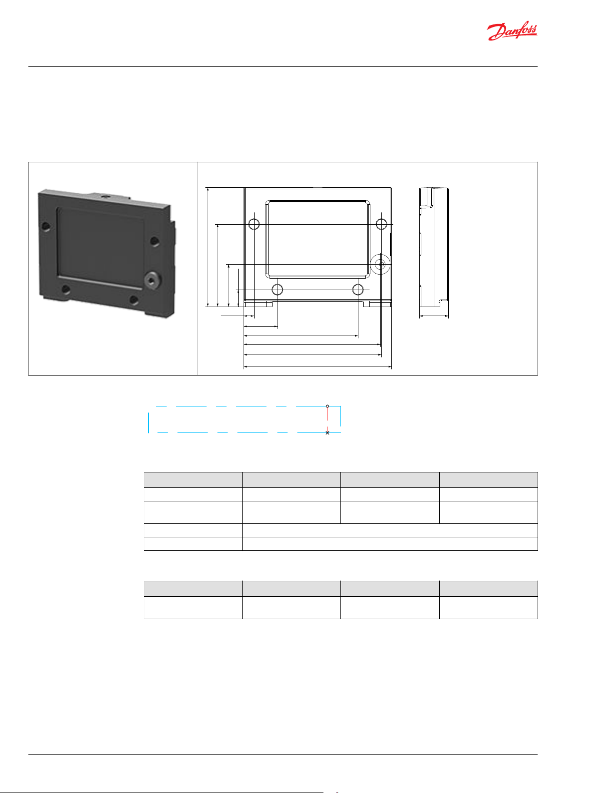
[4.51]114.5
[4.47]113.5
[3.74]95
[1.10]28
[4.84]123
[0.94]24
[1.38]35
[3.90]99
[2.70]68.5
[0.55]14
[0.33]8.5
Pneumatic
Technical Information
ECO 80 Directional Control Valve
EVO - end plate
EVO with pneumatic port
The EVO end plate closes off the valve stack section by placing it at the end. Furthermore, the end plate is
ensuring Load Sense (LS) is relieved to tank pressure when the valve is not operated. The pneumatic port
works as air inlet supply for when using the electro pneumatic actuator.
EVO with pneumatic port Dimensions
Schematic
Technical specification
Parameter Minimum Recommended range Maximum
Fluid temperature - 30°C [-22°F] 30 to 60°C [86 to 140°F] 90°C [194 °F]
Fluid viscosity 4 mm2/s [39 SUS] 12 to 75 mm2/s [65 to 347
460 mm2/s [2128 SUS]
SUS]
Fluid cleanliness 23/19/16 (according to ISO 4406)
Operating temperature Ambient: -30 to 60°C [-22 to 140°F]
Part numbers
Part number Description Pneumatic port Mounting
11191584 EVO End plate with
pneumatic port
G1/8-28 M8
68 | © Danfoss | September 2020 BC199786485316en-000301
Page 69
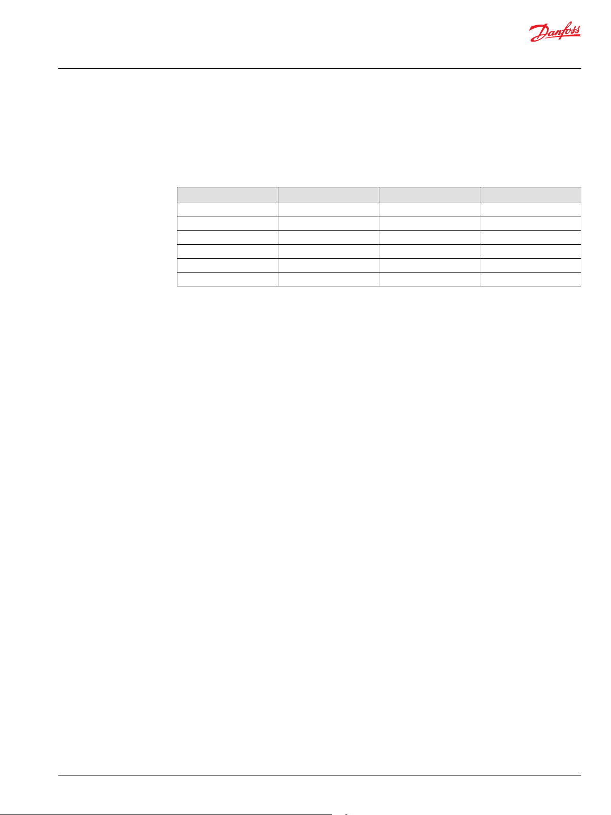
Technical Information
ECO 80 Directional Control Valve
EVT - assembly kit for both mechanical and electrical acting
EVT assembly kit for various ECO 80 combinations consist of four tie rods, eight washers, eight nuts and
O-ring. Use the guide and reference tables how to choose PVAS kit.
The tie rods are inserted through the entire length of the PVG valve stack. The nuts are tightened at the
pump side and at the end plate.
Part numbers
Number of EVB’s Part number Number of EVB’s Part number
1 11173102 7 11173108
2 11173103 8 11173109
3 11173104 9 11173110
4 11173105 10 11173111
5 11173106 11 11173112
6 11173107 12 11173113
©
Danfoss | September 2020 BC199786485316en-000301 | 69
Page 70

35.5 [1.40]
36.5 [1.44]
99.5 [3.92]
91.5 [3.60]
14.5 [0.57]
16.3 [0.64]
40 [1.57]
27.5 [1.08]
98 [3.86]
L2
45.5 [1.77]
27 [1.06]
12 [0.47]
103.7 [4.08]
L1
98 [3.86]
Technical Information
ECO 80 Directional Control Valve
ECO 80 dimension overview
Number of EVB’s 1 2 3 4 5 6 7 8 9 10 11 12
L1 mm [in]
L2 mm [in] 130
65
[2.56]
[5.12]
105
[4.13]
170
[6.69]
145
[5.71]
210
[8.27]
185
[7.28]
250
[9.84]
225
[8.86]
290
[11.42]
265
[10.43]
330
[12.99]
305
[12.01]
370
[14.57]
345
[13.58]
410
[16.14]
385
[15.16]
450
[17.72]
425
[16.73]
490
[19.29]
465
[18.31]
530
[20.87]
505
[19.88]
570
[22.44]
70 | © Danfoss | September 2020 BC199786485316en-000301
Page 71

Danfoss
Power Solutions GmbH & Co. OHG
Krokamp 35
D-24539 Neumünster, Germany
Phone: +49 4321 871 0
Danfoss
Power Solutions ApS
Nordborgvej 81
DK-6430 Nordborg, Denmark
Phone: +45 7488 2222
Danfoss
Power Solutions (US) Company
2800 East 13th Street
Ames, IA 50010, USA
Phone: +1 515 239 6000
Danfoss
Power Solutions Trading
(Shanghai) Co., Ltd.
Building #22, No. 1000 Jin Hai Rd
Jin Qiao, Pudong New District
Shanghai, China 201206
Phone: +86 21 2080 6201
Products we offer:
Hydro-Gear
www.hydro-gear.com
Daikin-Sauer-Danfoss
www.daikin-sauer-danfoss.com
Cartridge valves
•
DCV directional control
•
valves
Electric converters
•
Electric machines
•
Electric motors
•
Gear motors
•
Gear pumps
•
Hydraulic integrated
•
circuits (HICs)
Hydrostatic motors
•
Hydrostatic pumps
•
Orbital motors
•
PLUS+1® controllers
•
PLUS+1® displays
•
PLUS+1® joysticks and
•
pedals
PLUS+1® operator
•
interfaces
PLUS+1® sensors
•
PLUS+1® software
•
PLUS+1® software services,
•
support and training
Position controls and
•
sensors
PVG proportional valves
•
Steering components and
•
systems
Telematics
•
Danfoss Power Solutions is a global manufacturer and supplier of high-quality hydraulic and
electric components. We specialize in providing state-of-the-art technology and solutions
that excel in the harsh operating conditions of the mobile off-highway market as well as the
marine sector. Building on our extensive applications expertise, we work closely with you to
ensure exceptional performance for a broad range of applications. We help you and other
customers around the world speed up system development, reduce costs and bring vehicles
and vessels to market faster.
Danfoss Power Solutions – your strongest partner in mobile hydraulics and mobile
electrification.
Go to www.danfoss.com for further product information.
We offer you expert worldwide support for ensuring the best possible solutions for
outstanding performance. And with an extensive network of Global Service Partners, we also
provide you with comprehensive global service for all of our components.
Local address:
Danfoss can accept no responsibility for possible errors in catalogues, brochures and other printed material. Danfoss reserves the right to alter its products without notice. This also applies to products
already on order provided that such alterations can be made without subsequent changes being necessary in specifications already agreed.
All trademarks in this material are property of the respective companies. Danfoss and the Danfoss logotype are trademarks of Danfoss A/S. All rights reserved.
©
Danfoss | September 2020 BC199786485316en-000301
 Loading...