

Page 1

User Guide
Liquid cooled heavy duty inductor unit
EC-LTS1200-410
www.danfoss.com
Page 2
User Guide
EC-LTS1200-410
Revision history Table of revisions
Date Changed Rev
July 2021 Updated user guide 0201
2 | © Danfoss | July 2021 BC355449988603en-000201
Page 3

User Guide
EC-LTS1200-410
Contents
General information
Intended use of the user guide................................................................................................................................................... 4
Product naming convention........................................................................................................................................................ 4
Conformity according to standards...........................................................................................................................................4
Warranty.............................................................................................................................................................................................. 5
Terms and abbreviations...............................................................................................................................................................5
Responsibility of the manufacturer........................................................................................................................................... 6
Safety information
General safety statement...............................................................................................................................................................7
Safety message signal words....................................................................................................................................................... 7
Safety symbols...................................................................................................................................................................................7
Personal protective equipment.................................................................................................................................................. 8
Safety features...................................................................................................................................................................................9
Electromagnetic compatibility (EMC)....................................................................................................................................... 9
Installation safety..............................................................................................................................................................................9
Operation safety.............................................................................................................................................................................11
Product overview
Intended use of the electric device......................................................................................................................................... 13
System introduction..................................................................................................................................................................... 14
Cooling...............................................................................................................................................................................................14
Rating plate......................................................................................................................................................................................14
Tightening torques........................................................................................................................................................................15
Transportation and storage
Transportation................................................................................................................................................................................ 17
Receiving and unpacking............................................................................................................................................................17
Lifting................................................................................................................................................................................................. 17
Handling............................................................................................................................................................................................19
Storage...............................................................................................................................................................................................19
Installation
Required tools.................................................................................................................................................................................20
Mechanical installation................................................................................................................................................................20
Allowed mounting position..................................................................................................................................................20
Installation procedure.............................................................................................................................................................21
Cooling connections............................................................................................................................................................... 22
Recommended coolants........................................................................................................................................................22
Electrical installation.....................................................................................................................................................................23
Electrical connections............................................................................................................................................................. 23
Grounding...................................................................................................................................................................................23
Cable gland assembly and power line connection...................................................................................................... 25
Cabling and wiring...................................................................................................................................................................31
High voltage connections..................................................................................................................................................... 32
Low voltage connections.......................................................................................................................................................32
Operation
Operation conditions....................................................................................................................................................................34
Condition monitoring during operation...............................................................................................................................34
Maintenance
Regular maintenance................................................................................................................................................................... 35
Cooling system maintenance....................................................................................................................................................36
Cleaning............................................................................................................................................................................................ 36
Dismounting and disposal of the electric device
Troubleshooting
Aftersales
Service policy...................................................................................................................................................................................40
Service parts.....................................................................................................................................................................................40
©
Danfoss | July 2021 BC355449988603en-000201 | 3
Page 4
User Guide
EC-LTS1200-410
General information
Intended use of the user guide
Product naming convention
This user guide contains the installation, operation and maintenance instructions for the EC-LTS1200-410
liquid cooled heavy duty inductor unit.
This user guide contains instructions necessary to safely and properly handle, install and maintain the
electric device. They should be brought to the attention of anyone who installs or maintains the electric
device or associated equipment.
All of the safety warnings and instructions in this user guide must be followed to prevent injury to
personnel or damage to property. Only qualified and authorized personnel, familiar with health and
safety requirements and national legislation, shall be permitted to handle, install and maintain the
device.
This user guide must be kept for future reference during installation, operation and maintenance.
This user guide uses illustrations as examples only. Illustrations in this user guide may not necessarily
reflect all system features.
In this user guide the EC-LTS external inductance unit is referred to as the electric device.
The following naming convention is used to refer to electric device type code and options:
•
EC-LTS1200-XXX
Part of the name Explanation
EC Electric Converter
LTS1200 Type code part 1
XXX Type code part 2
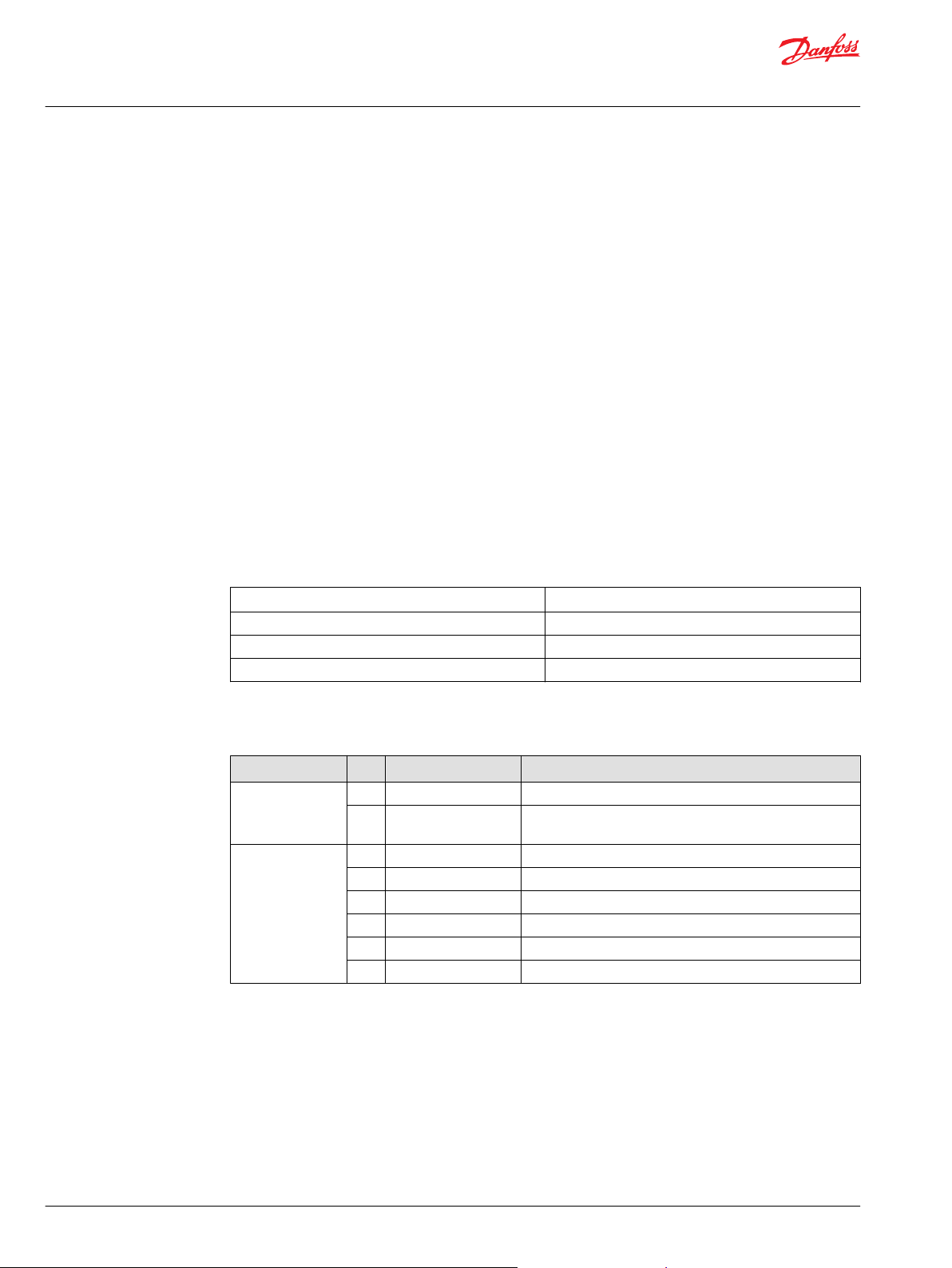
Options are presented in the Table below. Standard options are indicated by a star (*).
EC-LTS1200-410 options
Variant Code Description Additional information
Cable glands * No cable glands No cable glands or plugs
Marine classification * No marine classification
Conformity according to standards
The electric device has been designed in accordance with the essential parts of the following directives
and to meet the requirements of the standards:
+CG1 M25/M32 cable glands 3x M25 cable glands, 3x M32 cable glands and 2x M32 plugs
in delivery
+CL1 ABS American Bureau of Shipping
+CL2 BV Bureau Veritas
+CL3 DNV
+CL4 LR Lloyd’s Register
+CL5 RINA
4 | © Danfoss | July 2021 BC355449988603en-000201
Page 5
User Guide
EC-LTS1200-410
General information
Warranty
Applicable directives and standards
Directives / Standards Explanation
Low Voltage Directive 2014/35/EU Electrical equipment means any equipment designed for use with a voltage
The electromagnetic compatibility
(EMC) Directive 2014/30/EU
IEC/EN 61800-5-1: 2007 Adjustable speed electrical power drive systems - Part 5-1: Safety
EN 13766-1:2018 Construction machinery. Electromagnetic compatibility of machines with
UN Regulation No. 10 Revision 4 and
Revision 5
rating of between 50 and 1000 V for alternating current.
EMC directive ensures that electrical and electronic equipment does not
generate, or is affected by, electromagnetic disturbance.
requirements - Electrical, thermal and energy.
internal electrical power supply.
Uniform provisions concerning the approval of vehicles with regard to
electromagnetic compatibility.
Danfoss offers warranty against defects in workmanship and materials for its products for a period of
twelve (12) months from commissioning or eighteen months (18) from delivery (Incoterms-EXW),
whichever occurs first.
In order for the warranty to be valid, the customer must follow the requirements of this and all related
documents, especially those set out in the product installation and maintenance documents, as well as
the applicable standards and regulations in force in each country.
Defects arising from the improper or negligent use, operation, and/or installation of the equipment, nonexecution of regular preventive maintenance, as well as defects resulting from external factors or
equipment and components not supplied/recommended by Danfoss, will not be covered by the
warranty.
The warranty will not apply if the customer at its own discretion makes repairs and/or modifications to
the equipment without prior written consent from Danfoss.
Terms and abbreviations
Following symbols, terms and abbreviations may exist in this user guide.
Term/ Abbreviation Explanation
AC Alternating current
DC Direct current
MCB Miniature circuit breaker
EMC Electromagnetic compatibility
EMI Electromagnetic interference
Symbol Variable Unit
U
DC
U
ac
I
n
P
n
f
in/out
f
switch
I
peak
Q
c
T
c
DC link voltage V
AC output voltage V
Rated current A
Rated power kW
Input / Output frequency Hz
Switching frequency kHz
Overcurrent limit A
Rated coolant liquid flow l/min
Rated coolant liquid input
temperature
rms
°C
©
Danfoss | July 2021 BC355449988603en-000201 | 5
Page 6
User Guide
EC-LTS1200-410
General information
Symbol Variable Unit
T
amb
GND Ground in electrical connections
R Resistance Ω
Responsibility of the manufacturer
Danfoss is responsible for the safety, reliability and performance of the electric device only if:
Handling, mounting, installation, operation and maintenance are carried out by qualified and
•
authorized service personnel.
The installation of the system complies with the requirements of the appropriate regulations.
•
The electric device is used in accordance with the instructions in this user guide.
•
The electric device is installed, maintained and serviced in accordance with the instructions in this
•
user guide.
Rated ambient temperature °C
6 | © Danfoss | July 2021 BC355449988603en-000201
Page 7

User Guide
EC-LTS1200-410
Safety information
General safety statement
Safety message signal words
The electric device is intended for use as a component for industrial and commercial installations. The
end product containing the electric device must conform with all related regulations.
The use of the electric device is prohibited in hazardous areas unless it is expressly designed for such use.
The electric device is intended for installation, use and maintenance by qualified personnel, familiar with
health and safety requirements and national legislation. Ignoring these instructions may invalidate all
applicable warranties.
These instructions must be followed to ensure safe and proper installation, operation and maintenance
of the electric device. They should be brought to the attention of anyone who installs, operates or
maintains the electric device or associated equipment.
High voltage and rotating parts can cause serious or fatal injuries. For the electric device covered by this
user guide, it is important to observe safety precautions to protect personnel from possible injury.
Safety message signal words indicate the severity of a potential hazard.
DANGER Indicates an imminently hazardous situation which, if not avoided, will result in death or serious
injury.
WARNING Indicates a potentially hazardous situation which, if not avoided, could result in death or
serious injury.
CAUTION Indicates a potentially hazardous situation which, if not avoided, may result in minor or
moderate injury. CAUTION may also alert against unsafe practices
NOTICE Indicates a potentially hazardous situation which, if not avoided, could result in property
damage.
Safety symbols
The following safety and information related symbols may exist in this user guide and on the electric
device.
Danger
This symbol is identified by a yellow background, red octagonal band and a black
STOP text. It indicates a hazardous situation that causes severe injury or death.
Action indicated by this symbol may not be executed.
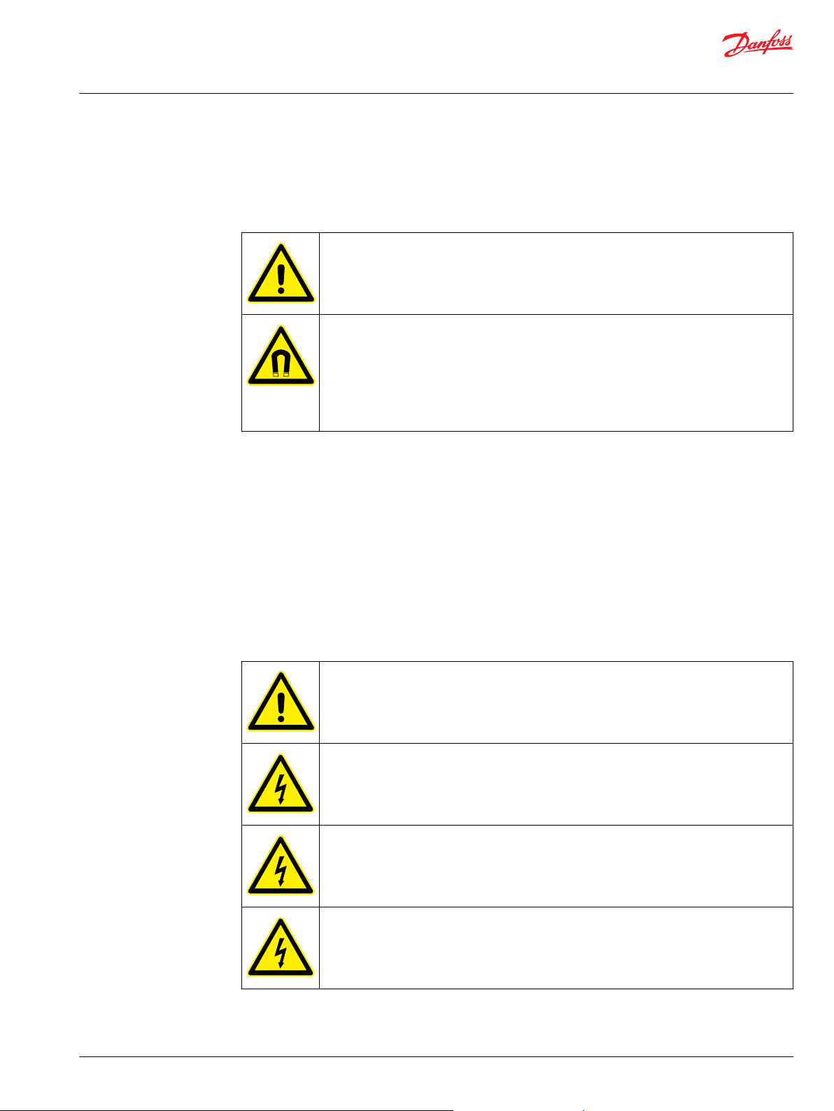
General warning
This symbol is identified by a yellow background, black triangular band, and a black
exclamation point symbol. It indicates a general potentially hazardous situation.
Electric shock warning
The symbol is identified by a yellow background, black triangular band, and a black
arrowhead symbol. It indicates dangerous electrical voltage that could cause an
electric shock to a person.
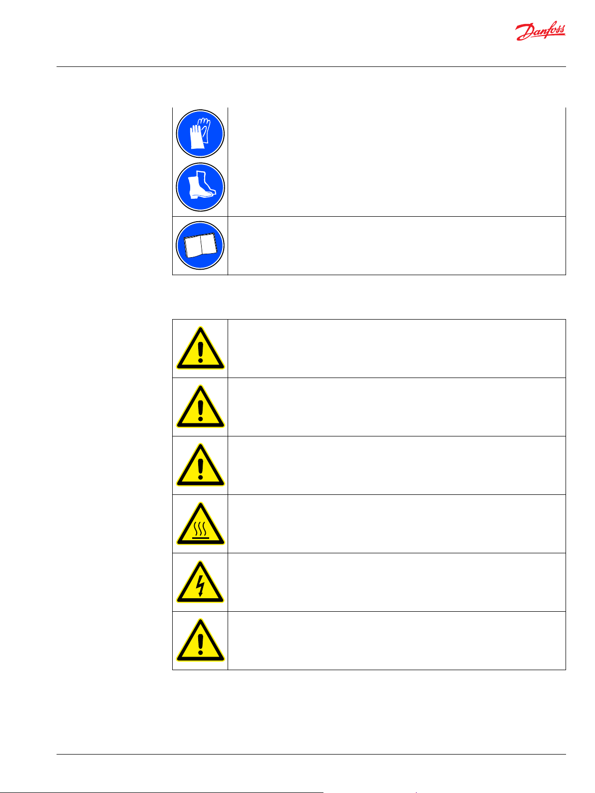
Burn warning
The symbol is identified by a yellow background, black triangular band, and a black
wavy lines- symbol. It indicates a hot device that could cause burns to a person.
The symbol also indicates that the device should be placed and installed so that
contact with its potentially hot surface is not possible.
©
Danfoss | July 2021 BC355449988603en-000201 | 7
Page 8
User Guide
EC-LTS1200-410
Safety information
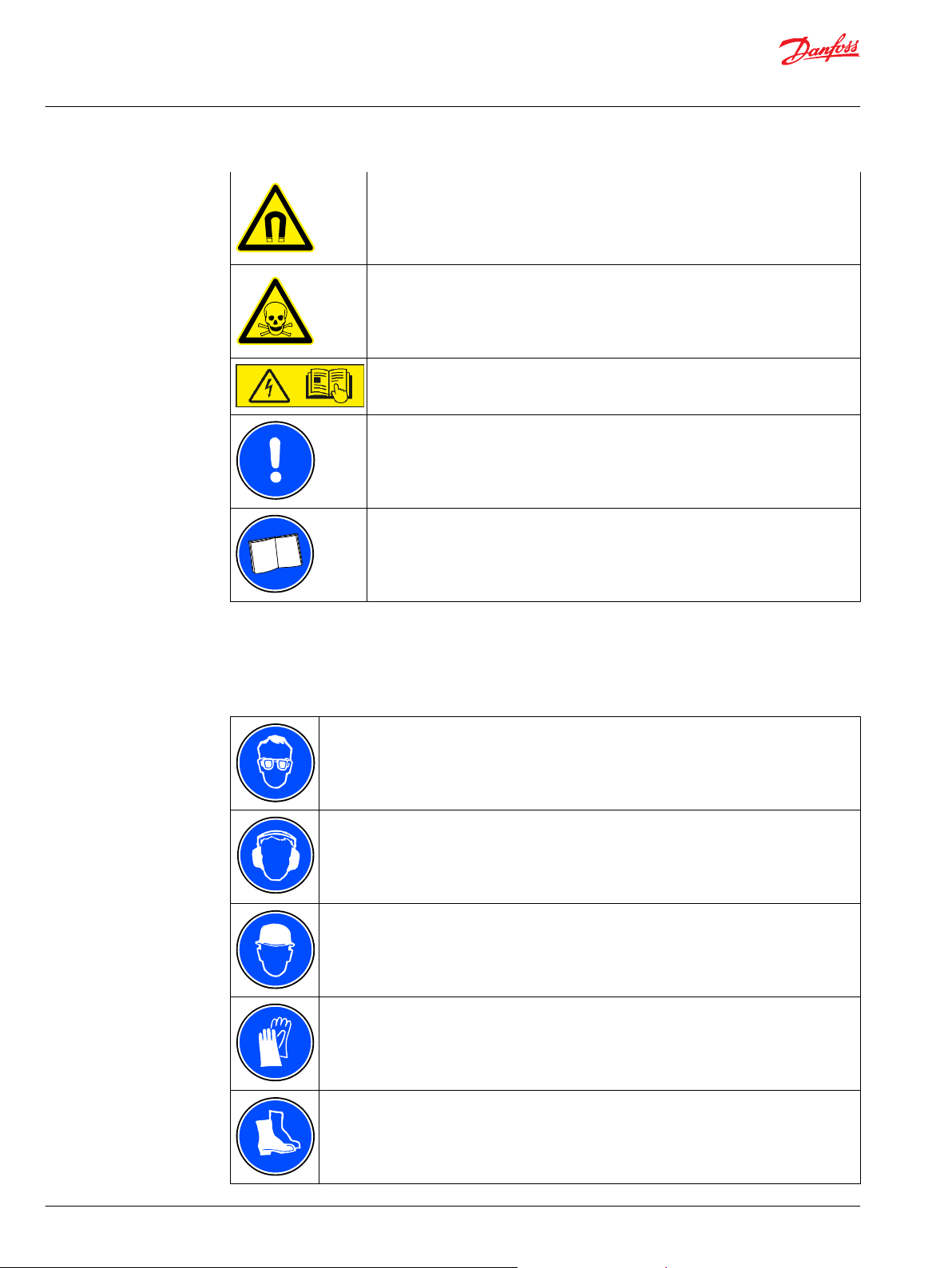
Magnet warning
The symbol is identified by a yellow background, black triangular band, and a black
magnet symbol. It indicates strong magnetic field that could cause harm to a person
or property.
Poison warning
The symbol is identified by a yellow background, black triangular band, and a skull
and crossbones symbol. It indicates a poisonous substance that could kill or cause an
injury to a person.
Electric shock warning - Read the instructions in the user guide.
General Information.
Read the instructions in the manual.
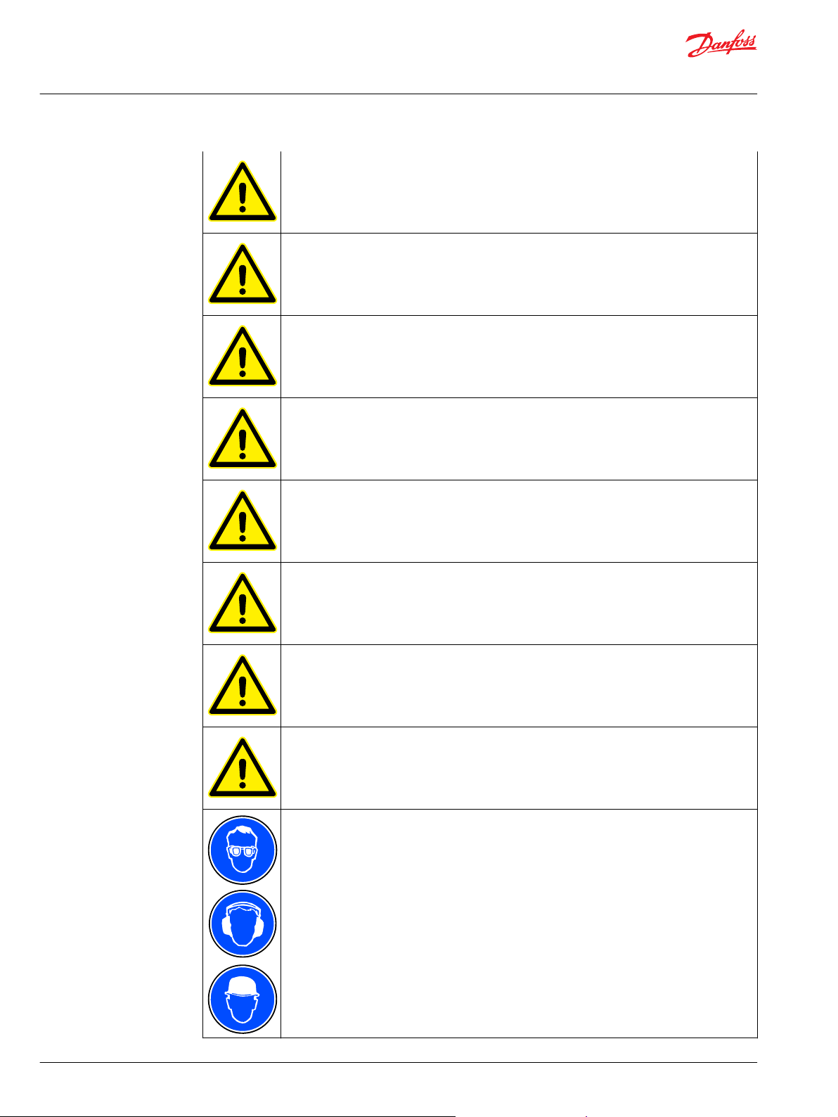
Personal protective equipment
Personal protective equipment shall be used when necessary during handling, installation and
maintenance of the electric device to avoid injury.
Use eye protective equipment like safety goggles or mask when you work with the electric
device. Permanent damage to the eye could be caused if bearing grease, melted nitrile rubber
(radial lip seal), glycol or other fluids splash.
Use hearing protective equipment when you work on the electric device. Hearing injuries can
be caused by too loud noise (noise in excess of 85 dBA).
Use head protective equipment like helmet when you lift the electric device! Head injuries can
be caused by object impact.
Use cut resistant gloves when you handle and maintain the electric device. There is a risk of
cut injuries.
Use protective footwear when you lift or move the electric device! Foot injuries could be
caused if lifting system or lifting brackets fail.
8 | © Danfoss | July 2021 BC355449988603en-000201
Page 9
User Guide
EC-LTS1200-410
Safety information
Safety features
Electromagnetic compatibility (EMC)
EMC stands for Electromagnetic compatibility. It is the ability of electric equipment to operate without
problems within an electromagnetic environment. Likewise, the equipment must not disturb or interfere
with any other product or system within its locality. This is a legal requirement for all equipment taken
into service within the European Economic Area (EEA).
Our products are designed with high standards of EMC in mind. Connect the power lines and groundings
along the instructions in this user guide to achieve the required level of EMI protection.
It is the responsibility of the installer to make sure that the equipment or system into which the product is
incorporated complies with the EMC legislation of the country of use. Within the European Union,
equipment into which this product is incorporated must comply with the EMC Directive 2014/30/EU.
When interfacing other equipment, connect only equipment that are specified as part of the
system and that are compatible.
Magnetic and electromagnetic fields generated near the current-carrying conductors and
permanent magnets in electric machines represent a health danger to persons with heart
pacemakers, metal implants and hearing aids. Persons with a heart pacemaker, metal
implants or hearing aids must consult a doctor before they enter the following areas:
•
Areas in which electric equipment and parts are operated
•
Areas in which electric equipment with permanent magnets are stored, mounted,
operated or repaired
If necessary, perform a special electromagnetic compatibility (EMC) test on the installation.
Installation safety
Only trained and qualified personnel familiar with the relevant safety requirements can
install the electric device. If the electric device is installed incorrectly it may lead to safety
hazard.
Make sure of correct grounding connections. Do not run the electric device without correctly
attached protective earth conductor. The grounding cable must be sufficient to carry the
maximum supply fault current which is normally limited by the fuses or Miniature Circuit
Breaker (MCB). Suitably rated fuses or MCB should be fitted in the mains supply of the electric
device, by the local legislation and recommendations.
Use only correct (type and value) protective fuses with the high voltage DC-system.
Do not do any work on the electric device control cables when the power is applied to the
electric device or to the external control circuits.
©
Danfoss | July 2021 BC355449988603en-000201 | 9
Page 10
User Guide
EC-LTS1200-410
Safety information
The control input functions of the electric device – for example stop/start must be secured
using independent channel protection in safety critical applications. All applications where
malfunction could cause injury or loss of life must be subject to a risk assessment and improve
control signal protection if needed.
Do not activate the automatic fault reset function on any system, where this may cause a
potentially dangerous situation. Reason for every fault situation should be determined
before resetting the fault.
Make sure that the supply voltage corresponds to the specification of the electric device.
Do not attempt to repair the electric device. In the case of suspected fault or malfunction,
contact Danfoss or Danfoss authorized service center for further assistance.
When you install the electric device, make sure that the cooling system and the used coolant
meet the specifications of the manufacturer. Make sure that the cooling system is in use when
the DC-link is powered.
If the control cabling is installed close with the power cabling, make sure that minimum
separation distance is 100 mm and crossings are at 90 degrees. Make sure that all terminal
connections are tightened correctly by the instructions.
Electric device must not be opened (excluding the connection box lid). Any attempt causes
loss of warranty.
Within the European Union, all machinery in which this product is used must comply with
Directive 98/37/EC, Safety of Machinery. In particular, the machine manufacturer is
responsible for providing a main switch and ensuring the electrical equipment complies with
EN60204-1.
Use correct personal protective equipment when you are near the electric device.
10 | © Danfoss | July 2021 BC355449988603en-000201
Page 11
User Guide
EC-LTS1200-410
Safety information
Operation safety
Read the instructions in this user guide before you start to install the electric device.
Do not use the electric device without correctly dimensioned and operating cooling system.
Maximum operation temperature must not be exceeded to avoid permanent damage to the
electrical device.
The requirements of this user guide and other related instructions and standards must be
followed.
Do not touch the electric device during operation. The surface of the electric device can be
hot.
This electric device is intended for professional use as complete equipment or system and as
part of a fixed installation. The electric device uses high voltages and currents, and it has
large amounts of stored electrical energy. Close attention is required to system design and
electrical installation to avoid hazards in either normal operation or in the event of
equipment malfunction.
The electric device can only be used in the applications it is intended for. The rated nominal
values and operational conditions are shown in the rating plate.
©
Danfoss | July 2021 BC355449988603en-000201 | 11
Page 12
User Guide
EC-LTS1200-410
Product overview
The advantages and features of the electric device:
Extremely compact design – 410 A.
•
High enclosure class IP67 – sealed from moisture and dust.
•
Ambient temperature -40ºC...105ºC.
•
Robust design withstanding high levels of mechanical vibrations and shocks.
•
Designed especially for highly cyclical loads typical in heavy mobile work machines.
•
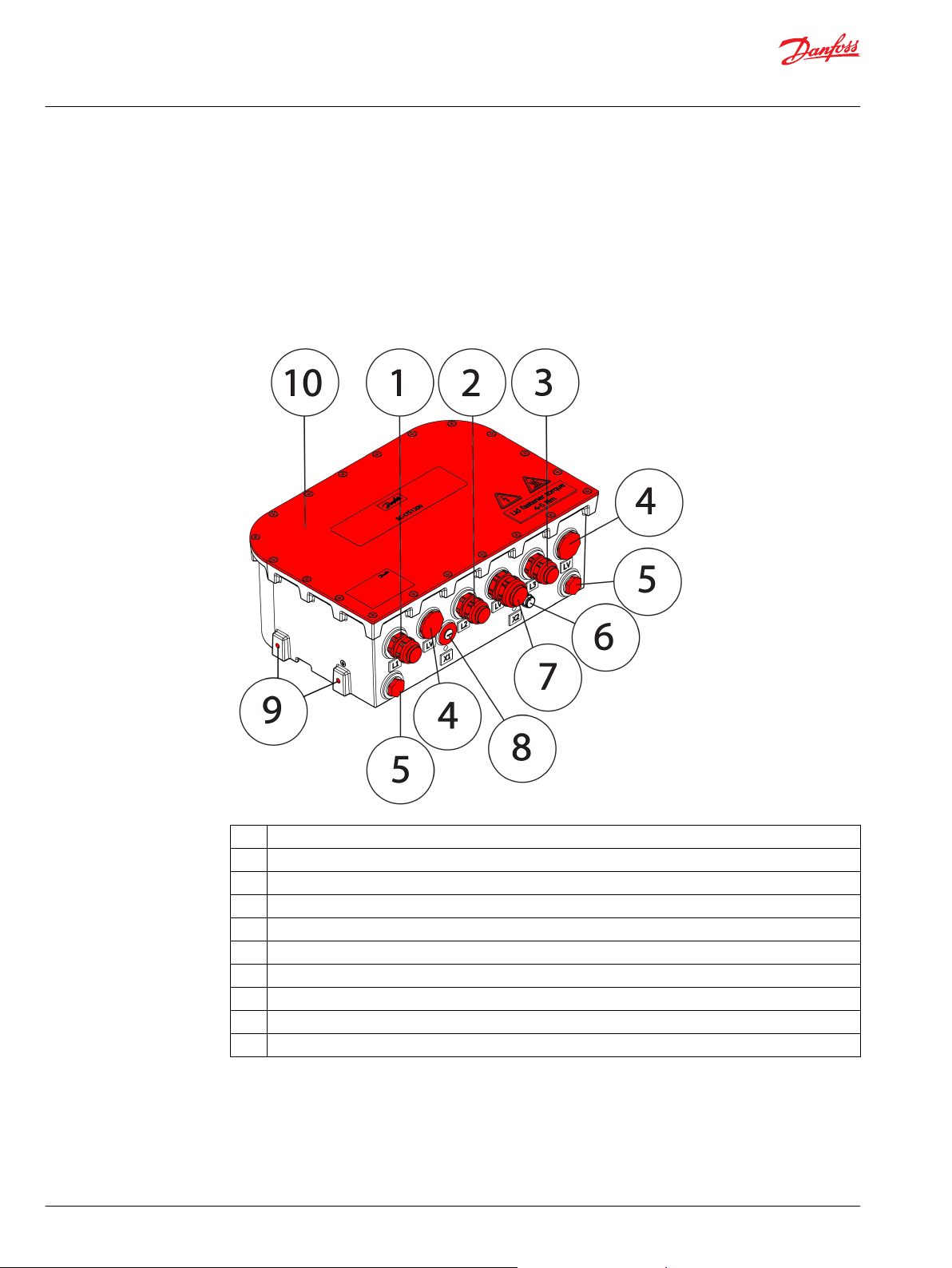
Main components
1 L1 connection
2 L2 connection
3 L3 connection
4 +LV connection plugged (configurable, see +CG option below)
5 Cooling inlet / outlet connections
6 X2 temperature measurement connector
7 +LV connection cable gland (configurable, see +CG option below)
8 X1 plugged, not in use
9 M8 Mounting points, 6 pcs on the sides and 8 pcs on the bottom
10 Connection box lid
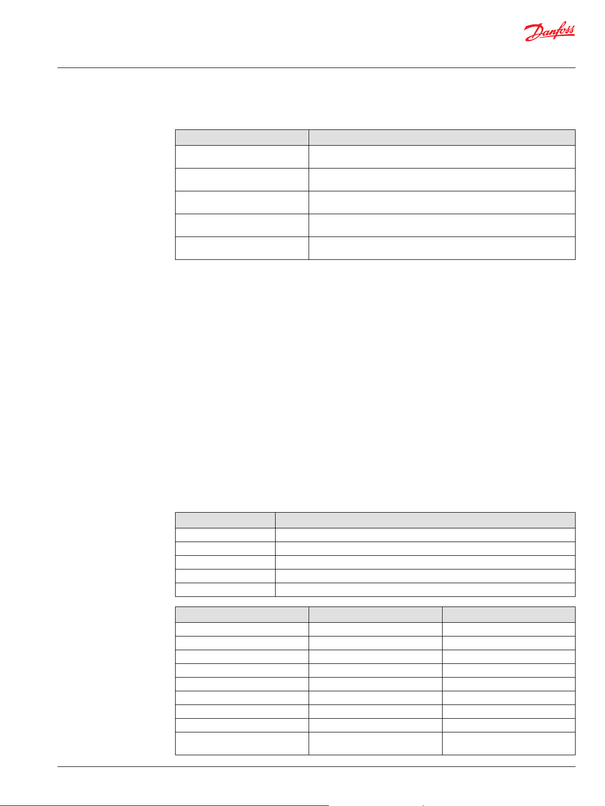
+CG1 option comes with a selection of cable glands and plugs. Typical cable gland configurations are
shown in the Table below.
12 | © Danfoss | July 2021 BC355449988603en-000201
Page 13
User Guide
EC-LTS1200-410
Product overview
Typical cable gland configurations for option +CG1
Connections Typical cable gland applications
Connection to DC/DCconverter (L1, L2, L3)
Low voltage side positive
connection (+LV)
Intended use of the electric device
3x M25 cable glands 3x M25 cable glands 3x M25 cable glands
1x M32 cable gland, 2x
M32 plugs
The electric device is intended only for professional use. Installation, operation and
maintenance of the electric device is permitted only for trained personnel and professionals.
The electric device is intended for fixed installation, as a part of complete power generation
equipment or system.
2x M32 cable glands, 1x
M32 plugs
3x M32 cable glands, no
plugs
Typical applications for the electric device are:
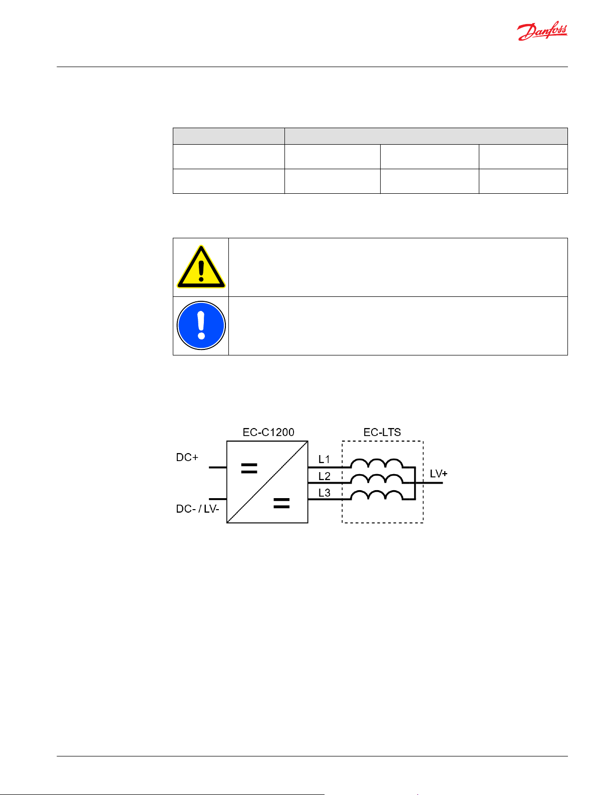
System component designed to be combined with EC-C1200-450 DCDC-converter, used to transfer
•
energy between two different voltage levels.
Application example
EC-C1200 DC/DC converter combined with the EC-LTS unit. LV+ and LV- can be connected, for example,
to battery and DC+ and DC- to DC-link. EC-C1200 would then control the battery discharging and
charging.
Not allowed use of the electric device
It is forbidden to use, handle, maintain and storage the electric device in following ways (including but
not limited to):
Using the electric device for other purposes than defined in the user guide.
•
Disregarding the obligation to comply with the user guide, safety signs and rating plate of the
•
electrical device.
Using the electric device, making adjustments and maintenance without first reading the user guide.
•
Exceeding the designed limits during the operation.
•
Using non-original service parts of wrong material causing corrosion problems and mechanical
•
failures in time.
Operating and performing maintenance on the electric device without appropriate personal
•
protective equipment.
Using the electric device for supporting other structures or indirect movements.
•
©
Danfoss | July 2021 BC355449988603en-000201 | 13
Page 14

User Guide
EC-LTS1200-410
Product overview
Causing any kind of impact forces to the electric device (for example hitting or hammering or
•
dropping objects).
Operating the electric device with electric connections other than defined in the user guide.
•
Operating the electric device with insufficiently tightened connections or cable glands.
•
Operating the electric device with power cables routed against the instructions.
•
Operating the electric device without properly dimensioned and operating cooling system.
•
Accessing the connection box(es) of the electric device, performing maintenance or adjustment
•
operations without securing that the electricity is disconnected and electric device is discharged as
defined in the user guide.
Lifting the electric device with additional load attached.
•
Using the electric device in potentially explosive environment.
•
Allowing dirt or liquid to enter into the electric device or connection box.
•
Using cables that can't withstand the maximum current values of the electric device.
•
Using dirty cable lugs or broken tools.
•
Connecting power cables so that there is less than 10 mm air gap between the cable lug and other
•
metallic structure (including the braid of the cable).
Storing the electric device contrary to the guidelines presented in this user guide, for
•
example, outdoors in wet or dusty conditions.
Storing the electric device without proper support that prevents overturning and falling.
•
System introduction
Cooling
Rating plate
For product specific and up to date information see product data sheets at https://www.danfoss.com/.
Cooling system requirements
Cooling system properties Specification
Cooling type Liquid cooling
Coolant type Water or water glycol mixture (glycol max. 50 %)
Coolant temperature -40º…+65 ºC
Coolant flow minimum 10 l/min
Maximum operating pressure 2 bar
Pressure drop 40 mbar with 10 l/min (+25 °C coolant)
See detailed information and specifications from the product data sheets at https://www.danfoss.com/.
Rated values can be found from the rating plate.
Each electric device has a rating plate (also called product label) which can be found on top of the electric
device. The rating plate contains device rating and identification details. The figure below shows an
example of a rating plate. The rating values in the Figure are illustrations only. For the exact information,
see the rating plate on the electric device and product data sheets at https://www.danfoss.com/.
14 | © Danfoss | July 2021 BC355449988603en-000201
Page 15

User Guide
EC-LTS1200-410
Product overview
Rating plate example
Rating plate fields
Field Explanation Unit
1 Electric device product family
2 Electric device device full type code including possible options
Serial No. Serial number
n ph Number of phases
U nom Nominal voltage V
U range Voltage range V
f1 Frequency Hz
I nom Nominal current A
P nom Nominal power VA
Manuf.
Duty Duty class
Cooling Cooling type
T
C
Q
C
IP rating Enclosure class according to IEC60034-5
Mass Total weight of the electric device
T
amb
T
storage
Max. pressure Coolant maximum pressure
Manufacturing year
Coolant temperature °C
Coolant flow l/min
Ambient temperature limits
Storage temperature limits °C
kg
°C
bar
The rating plate and its values shown here may not all be relevant for every electric device.
Tightening torques
For correct and safe operation, it is essential to use specified tightening torques for the electric device
screws. Tightening torques (screw preloads) used in the electric device are shown in the Table below.
©
Danfoss | July 2021 BC355449988603en-000201 | 15
Page 16

User Guide
EC-LTS1200-410
Product overview
Tightening torque tolerance is +/- 5% of the specified tightening torque.
Tightening torques
Connection Torque
Electric device mounting screws, M8 20 Nm
Connection box lid (power terminal cover) mounting screws 4 Nm
Cable lug mounting screws 15 Nm
Grounding cable mounting screws, M8 20 Nm
Cable gland (tighten from the frame of the gland) 15 Nm
16 | © Danfoss | July 2021 BC355449988603en-000201
Page 17

User Guide
EC-LTS1200-410
Transportation and storage
Transportation
Receiving and unpacking
Do not apply any excess weight on the electric device during transportation.
See the weight of the electric device from the product data sheets at https://
www.danfoss.com/.
The electric device is shipped in first class condition. Products are inspected and packed correctly to
prevent damage from ordinary handling during the transportation. Transportation conditions shall be in
accordance with the product specification, any kind of shocks must be avoided.
Plug and seal the cabling and cooling connections for transportation.
Lifting
Inspect the electric device and the package immediately upon arrival. Ensure that the rating plate data in
the cover letter complies with the purchase order. All external damage in the package or in the electric
device must be photographed and reported to Danfoss immediately.
Use correct, adequately dimensioned lifting devices and inspect them before lifting.
Do not apply any excess weight on the electric device when lifting it.
Use correct lifting slings. Use correct position and angle of lifting. The maximum permissible
range of lifting angles is shown in lifting figures.
Make sure that lifting slings are correctly routed so that they do not cause momentum on any
of the signal connectors.
See the rating plate and data sheets for weight information.
Lift the electric device using the correct lifting lugs/eyes only. See the lifting Figures in this
Chapter.
©
Danfoss | July 2021 BC355449988603en-000201 | 17
Page 18

User Guide
EC-LTS1200-410
Transportation and storage
Do not go under a lifted load.
The weight of the electric device is under 25 kg, so lifting it by hand is possible in most cases.
If it is necessary to lift the electric device with a lifting device, install two lifting eyes in the
threaded installation holes and lift from them. Obey the local legislation and
recommendations.
Correct lifting and incorrect lifting
Horizontal lifting
Maximum permissible lifting angles
18 | © Danfoss | July 2021 BC355449988603en-000201
Page 19

User Guide
EC-LTS1200-410
Transportation and storage
Horizontal lifting
Handling
Storage
1. M8 lifting eye, DIN580.
When turning or lifting the electric device, lift it in the air in order to prevent damage to the
frame or other parts of the electric device.
Although the electric device is designed to operate in harsh and demanding environment, any misuse or
improper handling of the electric device is prohibited to avoid malfunctions later.
When the device is dismounted and stored and packed for delivery, measure that there is no
voltage and then install short circuit wire to the conductor rails to prevent charge from
building up.
Do not apply any excess weight on the electric device during storage.
Store the electric device always indoors having the storage temperature preferably above -20 ºC and the
relative humidity less than 60 %. Storage conditions should be dry, dust free and vibration free.
Make sure that the cabling and cooling connections are plugged and sealed before storage.
The electric device must not be subjected to any external vibrations during storage to avoid possible
hidden structural damages.
©
Danfoss | July 2021 BC355449988603en-000201 | 19
Page 20

User Guide
EC-LTS1200-410
Installation
Required tools
Mechanical installation
Risk of electric shock during electrical installations. Use insulated tools..
Following tools are required to install the electric device:
•
Ratchet torque wrench.
•
Hex head wrench kit with different metric sizes.
•
Socket wrench kit with different metric sizes.
•
Cable gland tightening tool. Size according to cable glands.
•
Cable skinning knife.
•
Crimping tool for cable lugs.
For more detailed information, see appropriate Chapters in this user guide and product data sheets at
https://www.danfoss.com.
Allowed mounting position
Do not place the electric device on the ground without proper mounting or protective
structure.
The electric device must be mounted on a flat, heat- and flame-resistant mounting place (for example
•
on a bracket).
The electric device can be mounted in any direction. Mount the electric device permanently
•
from the mounting points.
Mounting points are shown in the Figure below.
•
Location of the mounting points
20 | © Danfoss | July 2021 BC355449988603en-000201
Page 21

User Guide
EC-LTS1200-410
Installation
1. M8x1.25 (18 mm Deep ) 14 pcs (6 pcs on the sides, 8 pcs on the bottom)
To fulfill the mechanical and environmental standards, for example vibration and shock, it is
recommended to mount the electric device from the bottom or from the side, with at least 6
pcs of M8 screws.
Selected mounting position must allow the cooling system to work properly. Bleed the air away from the
cooling channels to prevent air pockets.
Installation procedure
Risk of electric shock when the connection box lid is open. Make sure that the electric device is
discharged; measure the voltage to make sure of safety.
Heavy electric device. Handle with care. Handle the electric device correctly when you
install it to the correct mounting position. See Chapter Handling on page 19.
Measure the insulation resistance of the electric device before and after the installation of the
electric device.
When installing the connection box lid, make sure there are no foreign particles between the
connection box lid and the insulation and that all connection box fasteners are in place.
Missing or loose screws can compromise the insulation.
Preparations
Make sure that the chosen installation place fulfills the environmental requirements specified for the
•
electric device.
Protect the electric device against corrosive gases, liquids, conductive contaminants (such as
•
condensation, carbon dust, and metallic particles) and sprays or splashing water from all directions.
Protect the electric device in high humidity, salty or chemical content environments with suitable
•
additional enclosure.
The mounting place and mounting interfaces should be sufficient to carry the weight of the electric
•
device.
Make sure that the electric device has sufficient mounting and operating clearances for maintenance
•
work.
Installation procedure may vary from that shown in this user guide. All steps must be included in the
•
procedure, although the order of the steps can be different.
Installation procedure
1. Prepare the installation place and make sure that it meets the requirements for the product.
2. Lift and support the electrical device for the mounting. Refer to Chapter Lifting on page 17.
3. Install all appropriate mounting screws, do not tighten the screws until they are aligned and preinstalled. See the tightening torques from Chapter Tightening torques on page 15.
©
Danfoss | July 2021 BC355449988603en-000201 | 21
Page 22

User Guide
EC-LTS1200-410
Installation
4. Connect the cooling system. See Chapter Cooling connections on page 22 or the Main dimension
drawing for connection details. Make sure that there are no air pockets in the cooling channels and that
the coolant goes freely in and out. Make sure that the cooling system operates correctly.
5. Make sure that the devices and machines you will connect to the electric device have no voltage.
6. Make the grounding of the frame of the electric device by direct contact between it and the metal
bracket and / or from the protective earth contacts. The grounding contacts must be paint-free. See
Chapter Grounding on page 23.
Cooling connections
Make sure that cooling liquid runs freely in and out from the electric device.
When selecting cooling liquid nipples, choose nipples that can resist galvanic corrosion.
To prevent damage to the cooling connectors, refer to the documentation of the
manufacturer for the correct tightening torque of the cooling liquid nipples.
Connect the electric device directly to the cooling circuit.
•
Make sure that the coolant flow is equal or higher than rated and the coolant temperature at the inlet
•
of the electric device is lower or equal to the rated temperature.
For more information, see Chapter Recommended coolants on page 22 and product data sheets.
•
Rated values can be found on the rating plate of the electric device.
It is recommended to fix the hose on the coolant connection with a hose clamp or a hose clip after
•
the protection cap has been removed.
Use water/glycol mix or pure water with corrosion inhibitor as the coolant.
•
Recommended coolants
Ethylene glycol is a toxic compound. Avoid exposure to the coolant. Handle with care. Use
appropriate personal protective equipment when you handle the coolant.
The electric device works correctly with water based coolant. Plain water with appropriate corrosive
inhibitor is acceptable, for example water with maximum of 50% glycol coolant. Ethylene glycol based
Glysantin® G48® (includes also corrosion inhibitors) or similar can be used. Propylene glycol based
coolants, like Splash® RV&Marine antifreeze, can also be used. Propylene glycol is relatively safe
compound for humans and the environment.
22 | © Danfoss | July 2021 BC355449988603en-000201
Page 23

User Guide
EC-LTS1200-410
Installation
Electrical installation
Electrical connections
Before you start the electrical installation make sure that the frame of the electric device is
grounded correctly. Refer to Chapter Grounding on page 23.
Risk of electric shock when power terminal cover is open. When working with the power
connections make sure that electricity has been disconnected and the electric device has
discharged.
Cable lugs are not included in the delivery.
Grounding
Make sure that the electric device is correctly grounded. Do not operate the electric device
without correctly attached protective earth conductor. Obey the installation instructions and
the guidelines for component selection given in this user guide.
The grounding cable must be able to carry the maximum supply fault current which normally
will be limited by the fuses or the Miniature Circuit Breaker (MCB). Put correctly rated fuses or
MCB in the mains supply of the electrical device: obey the local legislation and
recommendations.
Obey the installation instructions and the guidelines for component selection given in this
user guide.
Make sure that the safety grounding is correct. Refer to Chapter Mechanical installation.
Generic grounding guidelines
•
Connect the ground terminal of each electric device individually to the site grounding bus bar
(through the filter if installed).
•
The grounding connections cannot loop from one electric device to another electric device, or to any
other piece of equipment, or from any other piece of equipment.
•
Ground impedance must be compliant with local industrial safety regulations.
•
The protective ground of the unit must be connected to the system ground. Ground impedance must
meet with the requirements of national and local industrial safety regulations and electrical
requirements. The condition of the grounding connections must be checked periodically.
•
Make sure that all grounding surfaces are clean and remove paint from the contact areas.
•
For detailed information, see appropriate Chapters in this user guide.
©
Danfoss | July 2021 BC355449988603en-000201 | 23
Page 24

User Guide
EC-LTS1200-410
Installation
Main frame
The best grounding is achieved when the main frame of each electric device is directly connected to the
ground. If this is not possible, the electric device must be grounded at least from one of the safety
grounding points with an appropriate grounding cable. For good functional grounding use wide flat
grounding braid. Round grounding wires are adequate for safety grounding but it does not provide very
good functional grounding because of its higher impedance at high frequencies. The grounding points
are marked to the electric device.
There are two marked safety grounding points, however, any of the mounting points can be used for
grounding.
Grounding points
1. Grounding connection: M8 hole. Refer to Main dimension drawing if necessary.
Safety grounding points and protective earth conductor
Touch current in the protective earth conductor exceeds 3,5 mA AC and 10 mA DC.
The cross sectional area of the protective earth conductor must be at least equal to that of the
incoming supply conductor.
One of the safety grounding points must be connected to adjacent building steel (girder, joist), a floor
ground rod, or bus bar. Grounding points must comply with national and local industrial safety
regulations and/or electrical codes.
Cabling and wiring
To make sure that the electric device functions correctly and to minimize the radiated emissions, all
connected cables and wires must be EMC-shielded. Shieldings must be connected to the ground at both
ends of the cable or wire. All power connections must be secured with cable lugs and cable glands. EMCshielded cable glands are used in all Danfoss products for the power connections. Make sure that the low
voltage cable (control signal cable) shield is also grounded from the both ends.
24 | © Danfoss | July 2021 BC355449988603en-000201
Page 25

User Guide
EC-LTS1200-410
Installation
Cable gland assembly and power line connection
Risk of electric shock when the connection box lid is not installed.
When you work with the power connections make sure that electricity has been disconnected
and the electric device has discharged. Measure the level of the remaining voltage before you
touch the power terminals.
Blueglobe cable gland tightening torques
Metric thread Nominal torque
M10x1,0 3,0 Nm
M12x1,5 5,0 Nm
M16x1,5 8,0 Nm
M20x1,5 10,0 Nm
M25x1,5 15,0 Nm
M32x1,5 15,0 Nm
M40x1,5 20,0 Nm
M50x1,5 30,0 Nm
M63x1,5 35,0 Nm
M75x1,5 80,0 Nm
M85x2,0 100,0 Nm
All electrical connections must be done according to instructions. It is essential to make sure that all
terminal connections are installed properly and the and the intended application is suitable for the
product in terms of electrical requirements/characteristics.
The cable harness for electric connections needs to be terminated with cable lugs and cable glands. It is
recommended to use IP67/68 rated, 360º shielded cable glands and single core automotive rated
screened cable.
The cable gland has three functions, it works as a stress relief, it seals the connection against water and
dirt and provides appropriate EMI shielding. Advanced cable glands could achieve high EMI attenuation
over a wide frequency range.
The cable lug and cable gland must be assembled according to instructions. For correct assembly of the
cable gland, it is recommended to use a torque key with a turnkey head and a key to adapt the cable
gland. The cable lug is connected to terminal with a M8 screw. Shielding of the power cable must be
connected to the electric device body by the cable gland. Recommendations for the tightening torques
must be followed. See the manufacturer's instructions on how to install the cable glands and the cable
lugs. The following instructions may not apply to every type of connection this electric device has.
©
Danfoss | July 2021 BC355449988603en-000201 | 25
Page 26

User Guide
EC-LTS1200-410
Installation
Cable harness connection with the cable lug and the cable gland (for illustration only)
EC-LTS1200-410 internal connections
Description
1 LV1
2 LV2
3 LV3
4 LV
The information below describes how to assemble screened power cables to the electric device. Pflitsch
BlueGlobe-series cable glands and H+S Radox Elastomer S automotive cables are recommended.
Cable gland assembly instruction can also be found from Pflitsch gland catalogue available from https://
www.pflitsch.de.
Cable lug and cable gland assembly steps
26 | © Danfoss | July 2021 BC355449988603en-000201
Page 27

User Guide
EC-LTS1200-410
Installation
1. Remove the small hexagonal piece from the BlueGlobe-sealing insert as shown in Figure below.
BlueGlobe-sealing
2. Cut the cable sheath at the distance A from the end of the cable, see Figure below. Pull the cut part of
the sheath partly (length B is from 10 to 15 mm) off the cable as shown in the figure. Distance A depends
of the length of the used cable lug. Measure with the cable lug that is used and cut to suitable length.
Install two layers of copper tape on the cable so that the distance B is covered. Use 3M
Copper Foil Tape 1181 or similar.
Do not remove the cable sheath completely at this point and do not cut the braid screen of
the cable.
™
Cut length of the cable sheath
3. Insert the cable to the cable gland with slight turning motion. This helps the cable go through the
spring inside the cable gland. Push the cable gland against the sheath of the cable as shown in Figure
below.
©
Danfoss | July 2021 BC355449988603en-000201 | 27
Page 28

User Guide
EC-LTS1200-410
Installation
Cable to the gland assembly
4. After the cable gland is in place remove the length A piece of the sheath and cut the braid screen
(cover) from 10 mm (distance C) from the gland bottom as shown in Figure below.
Make sure that the cable gland spring is against the cable sheath (that is protected with
copper tape) before cutting the braid screen.
Cut the braid screen
5. Cut a piece of length D of the inner sheath shown in Figure below. The length D must be equal to the
length of the cable lug body.
28 | © Danfoss | July 2021 BC355449988603en-000201
Page 29

User Guide
EC-LTS1200-410
Installation
Cutting the inner sheath
6. Make sure that the conducting strands of the cable are completely free of silicone and other impurities.
Place the cable inside the cable lug body, and crimp the cable lug twice in different places. See Figure
below.
Connecting cable lug
7. Cut piece of shrink tube and shrink it over the cable lug and braid screen as shown in Figure below.
This is done to keep the braid screen in place and for extra insulation.
The shrink tube must be specified for operating temperature range from -40 ºC to 150 ºC. Self
gluing shrink tube is recommended.
©
Danfoss | July 2021 BC355449988603en-000201 | 29
Page 30

User Guide
EC-LTS1200-410
Installation
Shrink tube
8. Insert the cable through the corresponding hole in the electric device frame and connect the cable lug
to the power terminal with the correct screw. Use spring washer between the cable lug and the
connection screw or nut. Do not tighten the cable lug screw at this point to ensure fitting of the cable
gland.
Make sure that there is at least 10 mm air gap between the cable lug and other metallic
structures including the braid of the cable. If the air gap is smaller, use extra insulation shrink
tube to cover the lug.
9. Screw the cable gland to the power terminals of the electric device according to instructions. Tighten
the cable gland with the specified torque.
Tighten the gable gland from the gable gland body to enclosure with torque 15 Nm. Then
tighten the cap of the gable gland according to the instructions provided by gable gland
manufacturer (recommendation Pflitsch).
10. Tighten the cable lug using the specified torque.
11. Repeat the procedure to the other cables and connections.
12. Close the power terminal cover and install the connector shield.
13. Make sure that the power cable shields are grounded properly.
30 | © Danfoss | July 2021 BC355449988603en-000201
Page 31

User Guide
EC-LTS1200-410
Installation
Cable lug and cable gland assembly cross section
Example of the equipment needed for the assembly
Description Manufacturer's homepage Art.No./Part No.
Assembly equipment (example) Torque key and turnkey
Assembly example for a 50 mm
cable
head
Key http://www.pflitsch.de SE30
2
Cable with nominal
cross-section of 50 mm
Cable lug http://www.druseidt.de 03903
Cable gland http://www.pflitsch.de
Screw http://www.wuerth.com DIN 912 M8x16 (item:
Washer http://www.wuerth.com DIN 2093, 8,2 x 16 x 0,9
Washer http://www.wuerth.com
Cabling and wiring
Route the power cables as far from the control signal wires as possible. The minimum
separating distance is 100 mm. The crossings must be in an angle of 90º. Power cables and
control wires should be routed near the frame of the application. Make sure that all terminal
connections are tightened correctly.
http://www.pflitsch.de 730N/10-50
http://www.hubersuhner.com Radox Elastomer S
2
Pflitsch blueglobe TRI bg
225ms tri
10285)
(item: 17332)
DIN 125 D8
(item: 10285)
Install the electric device by the instructions. Make sure that all the applications of the system, for
example, batteries are connected to the electric device by the instructions of this user guide and the
product specific guidelines.
©
Danfoss | July 2021 BC355449988603en-000201 | 31
Page 32

User Guide
EC-LTS1200-410
Installation
Cabling
•
For the power cables, it is recommended to use Radox Elastomer S, screened automotive cable or
equivalent cable with similar specifications.
•
Use only EMI-shielded power cables to make sure the correct operation of the electric device and to
minimize the radiated emissions. Cable shields must be connected to the electric device ground at
both ends of the cable. All Danfoss products use EMI-shielded cable glands for power connections.
Wiring
To make sure of correct and steady operation, use EMI-shielded cables for the control signals of the
electric device. Cable shields must be connected to the electric device ground at both ends of the cable.
Recommendations for control signal cables
Cable Cable type and properties
External temperature measurement (PT100/PT1000) shielded cable (twisted pair)
High voltage connections
The high voltage connections have a common ground connector.
U
≥ U
HV
LV
Make sure the power cables exit straight from the terminals and do not rub against the sharp
cable through-holes or other sharp edges which could wear out the cable insulation over
time.
Do not place any excess weight on the connection box lid(s).
The electric device must be installed and connected according to the instructions.
•
Make sure that all the connected applications are connected to the electric device according to the
•
product specific operating voltage.
The electric device is delivered with the power terminal cover mounted. To access the power
•
connections, remove the mechanical safety feature and the connection box lid.
For more information, see appropriate chapters in this user guide and the product data sheets.
Low voltage connections
See the correct signal connections and product specific pin-layout from product data sheets,
http://www.danfoss.com.
32 | © Danfoss | July 2021 BC355449988603en-000201
Page 33

User Guide
EC-LTS1200-410
Installation
Control signal connector information
Description Part number Supplier example
X2 temperature measurement connector M16 male 7.840.200.000 www.hummel.com
Insert 10-pole insert: 7.003.910.101
Pin: 7.010.981.001
Mating connector M16 female 7.810.400.000
Insert 10-pole, M16, RCPT 7.003.910.102
Sensor Connector Socket 7.010.981.002
M16 connector
Pin configuration of temperature measurements (M16 connector, one sensor per inductor)
PIN Description
1 Temperature 1, PT100 (P), inductor
2 Temperature 1, PT100 (N), inductor
3 Temperature 2, PT100 (P), inductor
4 Temperature 2, PT100 (N), inductor
5 Temperature 3, PT100 (P), inductor
6 Temperature 3, PT100 (N), inductor
7 Enclosure ground (shield)
8 Reserve
©
Danfoss | July 2021 BC355449988603en-000201 | 33
Page 34

User Guide
EC-LTS1200-410
Operation
Operation conditions
The electric device should be used for its intended purpose only and within limits specified by the
manufacturer, concerning:
Loading.
•
Cooling.
•
Service interval.
•
Ambient conditions such as temperature and moisture.
•
The electric device is designed for these conditions:
Maximum altitude 4000 m above sea level.
•
If the operation limits are exceeded and the electric device is damaged, please contact local Danfoss
representative.
Condition monitoring during operation
Risk of permanent damage to the electric device. Use the electric device only in the ambient
conditions given in this user guide and in the data sheet.
Risk of permanent damage to the electric device. Use the electric device only if the technical
guidelines given in this user guide and in the data sheet are met.
Risk of permanent damage to the electric device. If you notice deviations from the normal
operation (for example: high temperatures or noise), stop the electric device. Find the reason
for the deviation and take action to repair the functionality of the electric device. Refer to
Chapter Troubleshooting on page 39 for more information.
Temperature trip on the electric device is 155°C. Connect the three PT-100 temperature
sensors to the converter.
Monitor the electric device regularly during operation to make sure of reliable operation, to foresee
possible upcoming failures and to help to reach the designed lifetime of the product.
34 | © Danfoss | July 2021 BC355449988603en-000201
Page 35

User Guide
EC-LTS1200-410
Maintenance
Regular maintenance
Do not disassemble the electric device. You can do only procedures described in this user
guide. For further information contact Danfoss representative.
Only trained and qualified personnel that are familiar with the relevant safety requirements
can do any maintenance to the electric device.
Risk of electric shock when the connection box lid is removed.
Inspect the electric device at regular intervals. Use the regular maintenance checklists in the
inspections.
Do not attempt to tighten or release any screws, nuts or joints which are not shown in this
user guide and that are not involved in the normal installation and maintenance procedures.
Use correct personal protective equipment when you are near the electric device.
Read the instructions in the user guide before you install the electric device. To make sure of
safe and reliable operation of the electric device, obey the maintenance instructions.
©
Danfoss | July 2021 BC355449988603en-000201 | 35
Page 36

User Guide
EC-LTS1200-410
Maintenance
Maintenance intervals
Object Check/Task Weekly Monthly Yearly
General
construction
Electrical system Cables Visual check, for example wear. Replace if
Cooling system Operation Functioning. Cooling system functions as
Operation Abnormal phenomenon, for example noise or
Mounting Tightness of the screws. Tighten to proper
Enclosure and
connected parts
Electrical
connections
Groundings
(earthings)
Ventilation plug Cleanliness. Clean if necessary. See Chapter
heating. If clearly increased, contact Danfoss
representative.
value if necessary. Applies to screws that are
presented in this user guide. See Chapter
Tightening torques on page 15.
Check cleanliness. Clean if necessary. See
Chapter Cleaning on page 36.
necessary.
Check connections. Ensure that sufficient
tightening torque is applied to cable glands.
See Chapter Tightening torques on page 15.
Check groundings (earthings). Ensure that the
connection resistance is valid. Re-connect if
necessary.
specified.
Cleaning on page 36.
X
X
X
X
X
X
X
X
Cooling system maintenance
Cleaning
The cooling system of the electric device requires regular observation and maintenance
activities. Observe weekly that the cooling system operates correctly and check monthly that there are no
leakages in the cooling system. The quality of the coolant must be checked yearly. The mixture of water
and glycol as well as the type of the glycol used must be as specified. See Chapter Recommended coolants
on page 22.
Do not use pressure washer for cleaning. High water pressure may damage the gaskets
allowing water to go in to the electric device.
Never open or remove the watertight ventilation plugs. Clean them only from the outside.
Risk of electric shock if the electric device is cleaned against instructions allowing water to go
in to the electric device.
Keep the electric device clean. For cleaning, use non-abrasive and non-corrosive cleaning products. Make
sure that the detergent can be used for aluminum.
36 | © Danfoss | July 2021 BC355449988603en-000201
Page 37

User Guide
EC-LTS1200-410
Maintenance
Ventilation plug
©
Danfoss | July 2021 BC355449988603en-000201 | 37
Page 38

User Guide
EC-LTS1200-410
Dismounting and disposal of the electric device
Risk of electric shock if dismounting steps are continued before the electric device is
discharged and a safe voltage level has been measured.
Do not touch the electric device or continue to work with the electric device until it cools
down.
Support the electric device during dismounting, handle it with care.
Refer to Chapter Installation procedure on page 21 for additional information.
Dismounting procedure
1. Switch off the electric device.
2. Make sure that the cooling system remains operational.
3. Always measure that no voltage is present on the power terminals before you proceed.
4. Wait until the temperature of the electric device and cooling liquid has decreased below +40 °C.
5. Disconnect the power terminal cabling.
6. Disconnect grounding cables (protective earth).
7. Disconnect the liquid cooling system.
8. Remove the mounting screws and dismount the electric device from the mounting base.
9. Install the connection box lid and other parts and plug all electrical and cooling connections for longer
storage.
10. Lift the electric device off.
Disposal of the electric device
Dispose of the electric device and any of its parts by local laws and regulations.
38 | © Danfoss | July 2021 BC355449988603en-000201
Page 39

User Guide
EC-LTS1200-410
Troubleshooting
Do not activate the automatic fault reset function on any system where it can be the cause of a
potentially dangerous situation.
Do not try to repair the electric device. In the case of suspected fault or malfunction, contact
Danfoss or authorized service center for further assistance.
For the reason of general safety and correct operative actions, read the instructions carefully
before you start any analyses or work with the electric device.
Use correct personal protective equipment when you are near the electric device.
Some unexpected situations may occur while operating the electric device. Some of the possible causes
and actions are given in table below. If an unexpected situation occurs, it should be corrected as soon as
possible.
These instructions do not cover all details or variations in the equipment nor provide information for
every possible condition to be met in connection with installation, operation or maintenance.
Troubleshooting
Fault description Possible cause Action
Electric device
overheating
Significant coolant leak Loose connection in the
Electric device does not
work correctly or the
performance is poor
Cooling system failure. Inspect the cooling system operation and functionality,
especially possible leaks, flow rate and fluid temperature.
Change the cooling flow direction to flush the cooling
system from sediment possibly accumulated.
Leakage in the cooling
system.
Rigid particle inside the
cooling channel of the
electric device.
coolingsystem.
Broken cooling hose. Replace the cooling hose.
Poor powerline contacts
(high voltage)
Inspect the cooling system circuit and connections.
Try to pulsate coolant to open the channels.
Contact Danfoss representative.
Inspect, clean and tighten the connections. Replace them if
neccessary.
Inspect, clean and tighten the contacts.
©
Danfoss | July 2021 BC355449988603en-000201 | 39
Page 40

User Guide
EC-LTS1200-410
Aftersales
Service policy
Service parts
Maintenance and service of the electric device is limited to the procedures described in this user guide.
See Chapter Service parts on page 40 below for available service and accessory parts. For further
information, contact Danfoss representative.
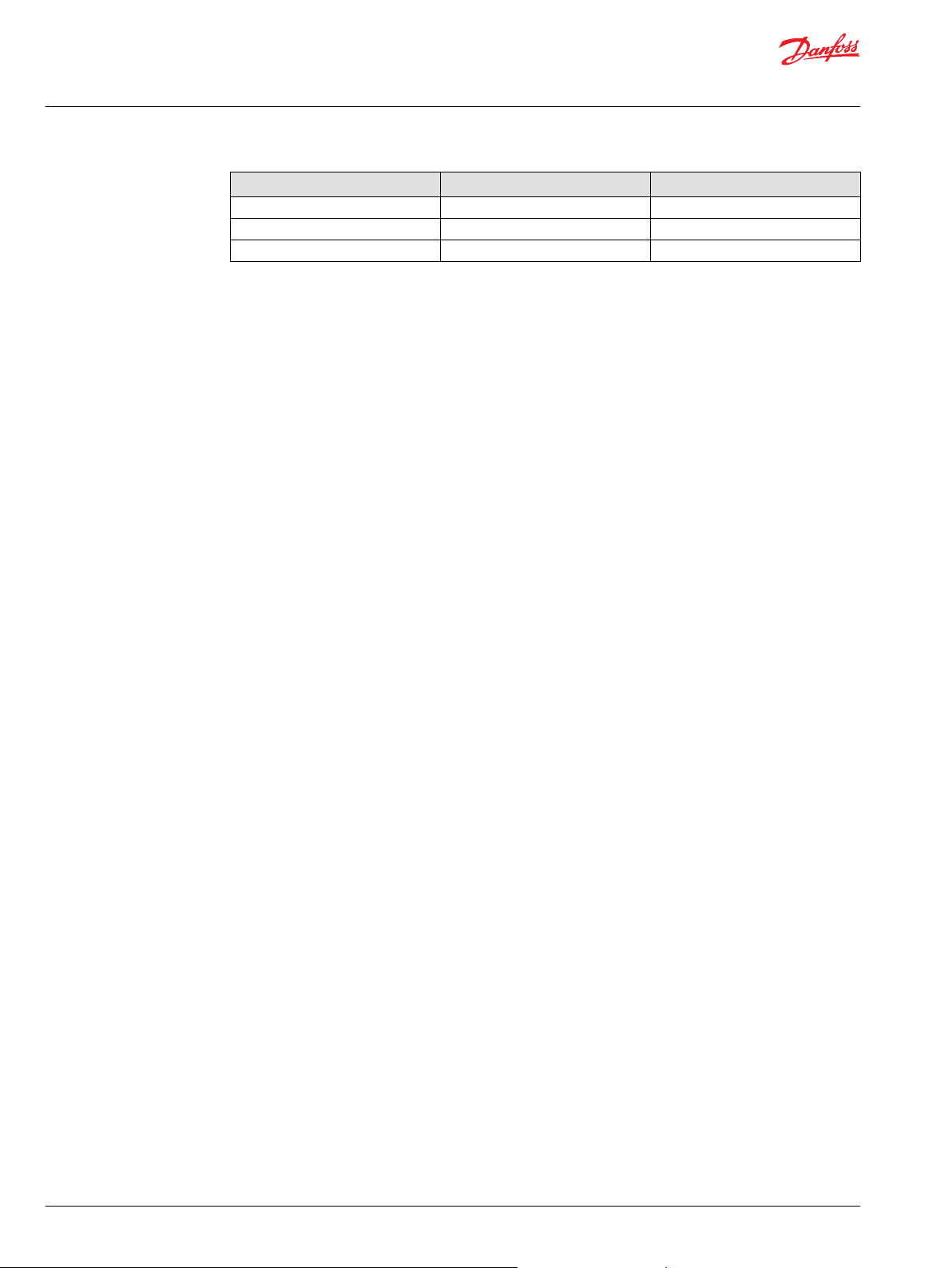
The recommended service parts are listed in the Table below. Contact Danfoss representative for more
information and purchasing.
Service parts
Service parts
Position Item / order number Quantity Description
1 35409 1 Lid with extruded gasket
2 10348 3 Cable gland, M25 x 1,5 BG PFLITSCH, BG225MSTRI
3 10473 3 Cable gland, M32 x 1,5 BG PFLITSCH, BG232MSTRI
4 34099 20 Lid screws, M5 x 12, DIN 965 A2 TX
40 | © Danfoss | July 2021 BC355449988603en-000201
Page 41

Danfoss
Power Solutions GmbH & Co. OHG
Krokamp 35
D-24539 Neumünster, Germany
Phone: +49 4321 871 0
Danfoss
Power Solutions ApS
Nordborgvej 81
DK-6430 Nordborg, Denmark
Phone: +45 7488 2222
Danfoss
Power Solutions (US) Company
2800 East 13th Street
Ames, IA 50010, USA
Phone: +1 515 239 6000
Danfoss
Power Solutions Trading
(Shanghai) Co., Ltd.
Building #22, No. 1000 Jin Hai Rd
Jin Qiao, Pudong New District
Shanghai, China 201206
Phone: +86 21 2080 6201
Products we offer:
Hydro-Gear
www.hydro-gear.com
Daikin-Sauer-Danfoss
www.daikin-sauer-danfoss.com
Cartridge valves
•
DCV directional control
•
valves
Electric converters
•
Electric machines
•
Electric motors
•
Gear motors
•
Gear pumps
•
Hydraulic integrated
•
circuits (HICs)
Hydrostatic motors
•
Hydrostatic pumps
•
Orbital motors
•
PLUS+1® controllers
•
PLUS+1® displays
•
PLUS+1® joysticks and
•
pedals
PLUS+1® operator
•
interfaces
PLUS+1® sensors
•
PLUS+1® software
•
PLUS+1® software services,
•
support and training
Position controls and
•
sensors
PVG proportional valves
•
Steering components and
•
systems
Telematics
•
Danfoss Power Solutions is a global manufacturer and supplier of high-quality hydraulic and
electric components. We specialize in providing state-of-the-art technology and solutions
that excel in the harsh operating conditions of the mobile off-highway market as well as the
marine sector. Building on our extensive applications expertise, we work closely with you to
ensure exceptional performance for a broad range of applications. We help you and other
customers around the world speed up system development, reduce costs and bring vehicles
and vessels to market faster.
Danfoss Power Solutions – your strongest partner in mobile hydraulics and mobile
electrification.
Go to www.danfoss.com for further product information.
We offer you expert worldwide support for ensuring the best possible solutions for
outstanding performance. And with an extensive network of Global Service Partners, we also
provide you with comprehensive global service for all of our components.
Local address:
Danfoss can accept no responsibility for possible errors in catalogues, brochures and other printed material. Danfoss reserves the right to alter its products without notice. This also applies to products
already on order provided that such alterations can be made without subsequent changes being necessary in specifications already agreed.
All trademarks in this material are property of the respective companies. Danfoss and the Danfoss logotype are trademarks of Danfoss A/S. All rights reserved.
©
Danfoss | July 2021 BC355449988603en-000201
 Loading...