


User Guide
Electrical converter
EC-C1200-450
www.danfoss.com

User Guide
EC-C1200-450
Revision history Table of revisions
Date Changed Rev
July 2021 Updated user guide 0201
2 | © Danfoss | July 2021 BC265735231757en-000201

User Guide
EC-C1200-450
Contents
General information
Safety information
Product overview
Transportation and storage
Installation
Operation
Maintenance
Intended use of the user guide................................................................................................................................................... 5
Product naming convention........................................................................................................................................................ 5
Connection options....................................................................................................................................................................9
Conformity according to standards........................................................................................................................................ 10
Warranty............................................................................................................................................................................................10
Terms and abbreviations.............................................................................................................................................................10
Responsibility of the manufacturer.........................................................................................................................................11
General safety statement............................................................................................................................................................12
Safety message signal words.....................................................................................................................................................12
Safety symbols................................................................................................................................................................................ 12
Personal protective equipment................................................................................................................................................13
Safety features.................................................................................................................................................................................14
Electromagnetic compatibility (EMC).....................................................................................................................................14
Installation safety...........................................................................................................................................................................15
Operation safety.............................................................................................................................................................................17
General specifications.................................................................................................................................................................. 19
Motor Control (+MC option, motor and generator control).....................................................................................21
Active Front End (+AFE option)...........................................................................................................................................22
Microgrid (+UG option)..........................................................................................................................................................23
DCDC converter (+DC option)............................................................................................................................................. 24
Intended use of the electric device......................................................................................................................................... 25
System introduction..................................................................................................................................................................... 26
Cooling...............................................................................................................................................................................................27
Rating plate......................................................................................................................................................................................27
Tightening torques........................................................................................................................................................................28
Transportation................................................................................................................................................................................ 29
Receiving and unpacking............................................................................................................................................................29
Lifting................................................................................................................................................................................................. 29
Handling............................................................................................................................................................................................30
Storage...............................................................................................................................................................................................30
Required tools.................................................................................................................................................................................32
Mechanical installation................................................................................................................................................................32
Allowed mounting position..................................................................................................................................................32
Installation procedure.............................................................................................................................................................34
Cooling connections............................................................................................................................................................... 37
Recommended coolants........................................................................................................................................................38
Electrical installation.....................................................................................................................................................................38
Electrical connections............................................................................................................................................................. 38
Grounding...................................................................................................................................................................................43
Cable gland assembly and power line connection...................................................................................................... 44
Cabling and wiring...................................................................................................................................................................52
High voltage connections..................................................................................................................................................... 52
Low voltage connections.......................................................................................................................................................54
Operation conditions....................................................................................................................................................................60
Pre-charging.................................................................................................................................................................................... 60
Condition monitoring during operation...............................................................................................................................61
Regular maintenance................................................................................................................................................................... 62
Cooling system maintenance....................................................................................................................................................63
Cleaning............................................................................................................................................................................................ 63
©
Danfoss | July 2021 BC265735231757en-000201 | 3

User Guide
EC-C1200-450
Contents
Dismounting and disposal of the electric device
Troubleshooting
Aftersales
Service policy...................................................................................................................................................................................69
Service parts.....................................................................................................................................................................................69
4 | © Danfoss | July 2021 BC265735231757en-000201

User Guide
EC-C1200-450
General information
Intended use of the user guide
Product naming convention
This user guide contains the installation, operation and maintenance instructions for the EC-C1200-450
electrical converter.
This user guide contains instructions necessary to safely and properly handle, install and maintain the
electric device. They should be brought to the attention of anyone who installs or maintains the electric
device or associated equipment.
All of the safety warnings and instructions in this user guide must be followed to prevent injury to
personnel or damage to property. Only qualified and authorized personnel, familiar with health and
safety requirements and national legislation, shall be permitted to handle, install and maintain the
device.
This user guide must be kept for future reference during installation, operation and maintenance.
This user guide uses illustrations as examples only. Illustrations in this user guide may not necessarily
reflect all system features.
In this user guide, the EC-C1200-450 electric converter is referred to as the electric device.
The following naming convention is used to refer to electric device type code and options:
•
EC-C1200-450-L+MC/+AFE/+UG/+DC
The rating plate of the electric device has the correct name of that particular electric device.
Part of the name Explanation
EC Electric Converter
C1200 Product name part 1
450 Product name part 2
L/S System size
+MC* Motor Control software -option
+AFE* Active Front End software -option
+UG* Microgrid (µgrid) software -option
+DC** DCDC-converter software -option
*Followed with number that represents the nominal current (A
): 120, 180, 240, 300, 350. These
RMS
options are available on the same electric device or alone.
**Followed with number that represents the nominal current (ADC): 150, 250, 300, 400. This option is not
available with other options.
Options are presented in the Table below. Standard options are indicated by a star (*).
EC-C1200-450 options
Variant Code Description Additional information
System size -S Small system Default EC-C unit for
individual or small system
installations
-L Large system EC-C unit for large system
installations
©
Danfoss | July 2021 BC265735231757en-000201 | 5

User Guide
EC-C1200-450
General information
EC-C1200-450 options (continued)
Variant Code Description Additional information
Control +MC70 Motor control, current limit 70 A Converter for motor/
generator applications
+MC120 Motor control, current limit 120 A Converter for motor/
+MC180 Motor control, current limit 180 A Converter for motor/
+MC240 Motor control, current limit 240 A Converter for motor/
+MC300 Motor control, current limit 300 A Converter for motor/
+MC350 Motor control, current limit 350 A Converter for motor/
+AFE70
+AFE120 Active front end, current limit 120 A Converter for active front
+AFE180 Active front end, current limit 180 A Converter for active front
+AFE240 Active front end, current limit 240 A Converter for active front
+AFE300 Active front end, current limit 300 A Converter for active front
+AFE350 Active front end, current limit 350 A Converter for active front
+UG70 Microgrid, current limit 70 A Converter for microgrid
+UG120 Microgrid, current limit 120 A Converter for microgrid
+UG180 Microgrid, current limit 180 A Converter for microgrid
+UG240 Microgrid, current limit 240 A Converter for microgrid
+UG300 Microgrid, current limit 300 A Converter for microgrid
+UG350 Microgrid, current limit 350 A Converter for microgrid
+DC150 DCDC control, current limit 150 ADC Converter for DC/DC
+DC250 DCDC control, current limit 250 ADC Converter for DC/DC
+DC300 DCDC control, current limit 300 ADC Converter for DC/DC
+DC400 DCDC control, current limit 400 ADC Converter for DC/DC
Speed option * Normal speed version (<580 Hz output
+HS High speed version (>580 Hz output
Active front end, current limit 70 A
frequency)
frequency)
generator applications
generator applications
generator applications
generator applications
generator applications
Converter for active front
end applications
end applications
end applications
end applications
end applications
end applications
applications
applications
applications
applications
applications
applications
applications
applications
applications
applications
EC-C with motor/generator
control firmware, capable
of speeds below 580 Hz
EC-C with motor/generator
control firmware, capable
of speeds up to 1000 Hz
6 | © Danfoss | July 2021 BC265735231757en-000201

User Guide
EC-C1200-450
General information
EC-C1200-450 options (continued)
Variant Code Description Additional information
Communication * CAN1939 EC-C with Standard
SAE1939-communication
+CO CANopen EC-C with CANopen-
communication
Connections * Normal connections EC-C with default HV
connections
+CE1 Connection extension 1 EC-C with double DC and
AC connectivity with
connection extension box 1
(double M25 cable gland
threads) (Not compatible
with +DCE option)
+CE2 Connection extension 2 EC-C with M32 cable gland
threads on AC connection
with connection extension
box 2 (choose also +DCE if
double DC connection is
required)
+DCE DC-extension EC-C with double DC-
connections: copper
bushings for double
connection (compatible
with +CE2/+CG4/+CG5)
Cable glands * No cable glands EC-C with no cable glands
or plugs
+CG1 Default M25 cable glands EC-C with 5x M25 cable
glands and 2x M25 plugs
+CG2 Default M25/M32 cable glands EC-C with 2x M25 cable
glands, 3xM32 cable glands
and 3xM25 plugs (for +CE2
option)
+CG3 Default M25 cable glands EC-C with 10x M25 cable
glands (for +CE1 option
with double DC-link
connections)
+CG4 Default M25 cable glands EC-C with 7x M25 cable
glands (for +DCE option)
+CG5 Default M25/M32 cable glands EC-C with 4x M25 cable
glands, 3xM32 cable glands
and 3xM25 plugs (for
combined +CE2 and +DCE
options)
+CG6 Default M25 cable glands EC-C with 8x M25 cable
glands and 2x M25 plugs
(for +CE1 option with single
DC-link connections)
©
Danfoss | July 2021 BC265735231757en-000201 | 7

User Guide
EC-C1200-450
General information
EC-C1200-450 options (continued)
Variant Code Description Additional information
Marine classification * No marine classification
+CL1 ABS American Bureau of
Shipping
+CL2 BV Bureau Veritas
+CL3 DNV
+CL4 LR Lloyd’s Register
+CL5 RINA
Customer specific * Default unit firmware-wise EC-C with no pre-set
parameters or application
+CS Customer specific parameters or
application in FW
EC-C with separately
specified application
and/or parameters
Electric device has option for small systems (S) and large systems (L). Small system option is typical for
vehicle applications and large system option is standard in marine applications because of the marine
regulations. Complete system should be looked when choosing the option as for example vehicle system
with many devices could also need the L-option to keep the isolation resistance or Y-capacitors at
reasonable level. In large and small system options, there are differences in the isolation measurement
resistance, DC-link discharge resistor and Y-capacitor values as shown in the Figure and Table below.
S- and L-systems schematics
S- and L-system component values
System option Component Value
Small (S) Resistors R1 and R2 (isolation measurement) 12 MΩ
Resistor R3 (discharge) 3.9 kΩ
Capacitors C1 and C2 (Y-capacitors) 330 nF
Capacitor C3 1 mF
Isolation resistance from DC-link to enclosure 6 MΩ
Large (L) Resistors R1 and R2 (isolation measurement) 240 MΩ
Resistor R3 (discharge) 39 kΩ
Capacitors C1 and C2 (Y-capacitors) 3.3 nF
Capacitor C3 1 mF
Isolation resistance from DC-link to enclosure 120 MΩ
8 | © Danfoss | July 2021 BC265735231757en-000201

User Guide
EC-C1200-450
General information
Connection options
Color coding
Color Meaning
Gray Cable glands for phases
Red Cable glands for DC+
Black Cable glands for DC-
©
Danfoss | July 2021 BC265735231757en-000201 | 9

User Guide
EC-C1200-450
General information
Conformity according to standards
The electric device has been designed in accordance with the essential parts of the following directives
and to meet the requirements of the standards:
Applicable directives and standards
Directives / Standards Explanation
Low Voltage Directive 2014/35/EU Electrical equipment means any equipment designed for use with a voltage
The electromagnetic compatibility
(EMC) Directive 2014/30/EU
IEC/EN 61800-5-1: 2007 Adjustable speed electrical power drive systems - Part 5-1: Safety
EN 13766-1:2018 Construction machinery. Electromagnetic compatibility of machines with
UN Regulation No. 10 Revision 4 and
Revision 5
Warranty
rating of between 50 and 1000 V for alternating current.
EMC directive ensures that electrical and electronic equipment does not
generate, or is affected by, electromagnetic disturbance.
requirements - Electrical, thermal and energy.
internal electrical power supply.
Uniform provisions concerning the approval of vehicles with regard to
electromagnetic compatibility.
Terms and abbreviations
Danfoss offers warranty against defects in workmanship and materials for its products for a period of
twelve (12) months from commissioning or eighteen months (18) from delivery (Incoterms-EXW),
whichever occurs first.
In order for the warranty to be valid, the customer must follow the requirements of this and all related
documents, especially those set out in the product installation and maintenance documents, as well as
the applicable standards and regulations in force in each country.
Defects arising from the improper or negligent use, operation, and/or installation of the equipment, nonexecution of regular preventive maintenance, as well as defects resulting from external factors or
equipment and components not supplied/recommended by Danfoss, will not be covered by the
warranty.
The warranty will not apply if the customer at its own discretion makes repairs and/or modifications to
the equipment without prior written consent from Danfoss.
Following symbols, terms and abbreviations may exist in this user guide.
Term/ Abbreviation Explanation
AC Alternating current
DC Direct current
MCB Miniature circuit breaker
EMC Electromagnetic compatibility
EMI Electromagnetic interference
Symbol Variable Unit
U
DC
U
ac
I
n
P
n
f
in/out
f
switch
DC link voltage V
AC output voltage V
Rated current A
Rated power kW
Input / Output frequency Hz
Switching frequency kHz
rms
10 | © Danfoss | July 2021 BC265735231757en-000201

User Guide
EC-C1200-450
General information
Symbol Variable Unit
I
peak
Q
c
T
c
T
amb
GND Ground in electrical connections
R Resistance Ω
Responsibility of the manufacturer
Danfoss is responsible for the safety, reliability and performance of the electric device only if:
Handling, mounting, installation, operation and maintenance are carried out by qualified and
•
authorized service personnel.
The installation of the system complies with the requirements of the appropriate regulations.
•
The electric device is used in accordance with the instructions in this user guide.
•
The electric device is installed, maintained and serviced in accordance with the instructions in this
•
user guide.
Overcurrent limit A
Rated coolant liquid flow l/min
Rated coolant liquid input
temperature
Rated ambient temperature °C
°C
©
Danfoss | July 2021 BC265735231757en-000201 | 11

User Guide
EC-C1200-450
Safety information
General safety statement
Safety message signal words
The electric device is intended for use as a component for industrial and commercial installations. The
end product containing the electric device must conform with all related regulations.
The use of the electric device is prohibited in hazardous areas unless it is expressly designed for such use.
The electric device is intended for installation, use and maintenance by qualified personnel, familiar with
health and safety requirements and national legislation. Ignoring these instructions may invalidate all
applicable warranties.
These instructions must be followed to ensure safe and proper installation, operation and maintenance
of the electric device. They should be brought to the attention of anyone who installs, operates or
maintains the electric device or associated equipment.
High voltage and rotating parts can cause serious or fatal injuries. For the electric device covered by this
user guide, it is important to observe safety precautions to protect personnel from possible injury.
Safety message signal words indicate the severity of a potential hazard.
DANGER Indicates an imminently hazardous situation which, if not avoided, will result in death or serious
injury.
WARNING Indicates a potentially hazardous situation which, if not avoided, could result in death or
serious injury.
CAUTION Indicates a potentially hazardous situation which, if not avoided, may result in minor or
moderate injury. CAUTION may also alert against unsafe practices
NOTICE Indicates a potentially hazardous situation which, if not avoided, could result in property
damage.
Safety symbols
The following safety and information related symbols may exist in this user guide and on the electric
device.
Danger
This symbol is identified by a yellow background, red octagonal band and a black
STOP text. It indicates a hazardous situation that causes severe injury or death.
Action indicated by this symbol may not be executed.
General warning
This symbol is identified by a yellow background, black triangular band, and a black
exclamation point symbol. It indicates a general potentially hazardous situation.
Electric shock warning
The symbol is identified by a yellow background, black triangular band, and a black
arrowhead symbol. It indicates dangerous electrical voltage that could cause an
electric shock to a person.
Burn warning
The symbol is identified by a yellow background, black triangular band, and a black
wavy lines- symbol. It indicates a hot device that could cause burns to a person.
The symbol also indicates that the device should be placed and installed so that
contact with its potentially hot surface is not possible.
12 | © Danfoss | July 2021 BC265735231757en-000201

User Guide
EC-C1200-450
Safety information
Magnet warning
The symbol is identified by a yellow background, black triangular band, and a black
magnet symbol. It indicates strong magnetic field that could cause harm to a person
or property.
Poison warning
The symbol is identified by a yellow background, black triangular band, and a skull
and crossbones symbol. It indicates a poisonous substance that could kill or cause an
injury to a person.
Electric shock warning - Read the instructions in the user guide.
General Information.
Read the instructions in the manual.
Personal protective equipment
Personal protective equipment shall be used when necessary during handling, installation and
maintenance of the electric device to avoid injury.
Use eye protective equipment like safety goggles or mask when you work with the electric
device. Permanent damage to the eye could be caused if bearing grease, melted nitrile rubber
(radial lip seal), glycol or other fluids splash.
Use hearing protective equipment when you work on the electric device. Hearing injuries can
be caused by too loud noise (noise in excess of 85 dBA).
Use head protective equipment like helmet when you lift the electric device! Head injuries can
be caused by object impact.
Use cut resistant gloves when you handle and maintain the electric device. There is a risk of
cut injuries.
Use protective footwear when you lift or move the electric device! Foot injuries could be
caused if lifting system or lifting brackets fail.
©
Danfoss | July 2021 BC265735231757en-000201 | 13

User Guide
EC-C1200-450
Safety information
Safety features
Protection type Built-in Information
Overcurrent Yes 750 A
Overvoltage Yes
Short circuit Yes Overspeed (+MC -option only) Yes Adjustable according to controlled
Overheat (electric device internal
temperature)
Emergency stop Yes Hardware secured device switch OFF
Yes Sophisticated thermal model that can
peak
1050 V
DC
motor
lower the current if needed
feature
In addition to the electrical protection features, the electric device has mechanical safety feature, a
connector shield, which prevents direct entry to the power terminals, when the electric device is
powered ON. The connector shield is a sheet metal component, which secures the power terminal cover
and it cannot be released without disconnecting the control signal connector (X1-connector) first. When
X1-connector is disconnected, it shuts down the electric device and starts electrical energy discharging
process.
Connector shield (mechanical safety feature)
Electromagnetic compatibility (EMC)
When interfacing other equipment, connect only equipment that are specified as part of the
system and that are compatible.
Magnetic and electromagnetic fields generated near the current-carrying conductors and
permanent magnets in electric machines represent a health danger to persons with heart
pacemakers, metal implants and hearing aids. Persons with a heart pacemaker, metal
implants or hearing aids must consult a doctor before they enter the following areas:
14 | © Danfoss | July 2021 BC265735231757en-000201

User Guide
EC-C1200-450
Safety information
Installation safety
•
Areas in which electric equipment and parts are operated
•
Areas in which electric equipment with permanent magnets are stored, mounted,
operated or repaired
If necessary, perform a special electromagnetic compatibility (EMC) test on the installation.
EMC stands for Electromagnetic compatibility. It is the ability of electric equipment to operate without
problems within an electromagnetic environment. Likewise, the equipment must not disturb or interfere
with any other product or system within its locality. This is a legal requirement for all equipment taken
into service within the European Economic Area (EEA).
Our products are designed with high standards of EMC in mind. Connect the power lines and groundings
along the instructions in this user guide to achieve the required level of EMI protection.
It is the responsibility of the installer to make sure that the equipment or system into which the product is
incorporated complies with the EMC legislation of the country of use. Within the European Union,
equipment into which this product is incorporated must comply with the EMC Directive 2014/30/EU.
Only trained and qualified personnel familiar with the relevant safety requirements can
install the electric device. If the electric device is installed incorrectly it may lead to safety
hazard.
Do not do any flash tests or voltage withstand tests on the electric device. If electrical tests or
measurements are required, do the tests with the electric device disconnected and stored
energy discharged.
Disconnect and isolate the electric device before you start any work on it. High voltages are
present at the terminals and within the inverter. Passive discharging of the DC-link capacitor
is done by the bleeder-resistor. Discharging below 50 Volts is completed within 8 minutes
after the power is disconnected. Make sure that voltage is not present on any inverter power
terminals prior you start any work on it.
Make sure of correct grounding connections. Do not run the electric device without correctly
attached protective earth conductor. The grounding cable must be sufficient to carry the
maximum supply fault current which is normally limited by the fuses or Miniature Circuit
Breaker (MCB). Suitably rated fuses or MCB should be fitted in the mains supply of the electric
device, by the local legislation and recommendations.
Use only correct (type and value) protective fuses with the high voltage DC-system.
Do not do any work on the electric device control cables when the power is applied to the
electric device or to the external control circuits.
The control input functions of the electric device – for example stop/start must be secured
using independent channel protection in safety critical applications. All applications where
malfunction could cause injury or loss of life must be subject to a risk assessment and improve
control signal protection if needed.
©
Danfoss | July 2021 BC265735231757en-000201 | 15

User Guide
EC-C1200-450
Safety information
The electric device can start at power up if the start- input signal is present.
The STOP function does not remove potentially lethal high voltages. Isolate the electric
device and wait for 8 minutes before you start any work with it. Never do any work on the
electric device, external devices or electric cables if the input power is connected to the
electric device.
Do not activate the automatic fault reset function on any system, where this may cause a
potentially dangerous situation. Reason for every fault situation should be determined
before resetting the fault.
Make sure that the supply voltage corresponds to the specification of the electric device.
Do not attempt to repair the electric device. In the case of suspected fault or malfunction,
contact Danfoss or Danfoss authorized service center for further assistance.
When you install the electric device, make sure that the cooling system and the used coolant
meet the specifications of the manufacturer. Make sure that the cooling system is in use when
the DC-link is powered.
If the control cabling is installed close with the power cabling, make sure that minimum
separation distance is 100 mm and crossings are at 90 degrees. Make sure that all terminal
connections are tightened correctly by the instructions.
Electric device must not be opened (excluding the connection box lid). Any attempt causes
loss of warranty.
Within the European Union, all machinery in which this product is used must comply with
Directive 98/37/EC, Safety of Machinery. In particular, the machine manufacturer is
responsible for providing a main switch and ensuring the electrical equipment complies with
EN60204-1.
Use correct personal protective equipment when you are near the electric device.
16 | © Danfoss | July 2021 BC265735231757en-000201

User Guide
EC-C1200-450
Safety information
Read the instructions in this user guide before you start to install the electric device.
Operation safety
Do not use the electric device without correctly dimensioned and operating cooling system.
Maximum operation temperature must not be exceeded to avoid permanent damage to the
electrical device.
The requirements of this user guide and other related instructions and standards must be
followed.
Make sure that the cooling system is in use when the DC-link is powered.
Do not touch the electric device during operation. The surface of the electric device can be
hot.
This electric device is intended for professional use as complete equipment or system and as
part of a fixed installation. The electric device uses high voltages and currents, and it has
large amounts of stored electrical energy. Close attention is required to system design and
electrical installation to avoid hazards in either normal operation or in the event of
equipment malfunction.
©
Danfoss | July 2021 BC265735231757en-000201 | 17

User Guide
EC-C1200-450
Safety information
The electric device can only be used in the applications it is intended for. The rated nominal
values and operational conditions are shown in the rating plate.
18 | © Danfoss | July 2021 BC265735231757en-000201

User Guide
EC-C1200-450
Product overview
General specifications
Electric device
The electric device is a heavy-duty converter designed especially for electric or hybrid drive trains for
mobile work machines, buses or marine vessels. Depending on the options selected, it can act as a motor
inverter (+MC option), active front end (+AFE option) or a DCDC-converter (+DC option), or it can create a
microgrid (+UG option).
The advantages and features of the electric device:
•
Extremely compact structure, weight only 15 kg.
•
Robust design withstanding high levels of mechanical vibrations and shocks.
•
High protection class IP67 ensuring operation in extreme conditions.
•
Wide ambient temperature range from -40 ºC...105 ºC.
•
Liquid cooling.
•
Wide allowed coolant temperature range.
•
Multiple mounting possibilities.
•
Designed especially for highly cyclical loads typical in heavy mobile work machines.
•
Controls both induction and permanent magnet motors with or without sensor.
•
Speed and torque reference motor control.
•
Generator control mode for DC-link voltage control.
•
Flexible control interface –CAN, resolver, analog, digital inputs/outputs.
•
PowerUSER PC-program for commissioning available.
•
Various communication protocols, for example CANopen, SAE J-1939.
•
Possibility to create customer specific applications with CODESYS (IEC61131-3) software tool.
•
High performance vector control.
•
Wide selection of protective safety functions.
These electric devices are designed for variety of applications:
•
Boosting battery voltage to higher DC-link voltage. (+DC option)
•
Charging high voltage batteries from higher DC-link voltage. (+DC option)
•
Converting alternating current (AC) from electrical generator to direct current (+MC option) for
energy storage
•
Active Front End for connecting to AC grid with regenerative power and low harmonic. (+AFE option)
•
Creating standalone microgrid (+UG option)
Note that +DC option functions together with an EC-LTS unit which is sold separately.
Note also that +AFE and +UG options require an external LCL-filter unit or a transformer and LC-filter
combination.
©
Danfoss | July 2021 BC265735231757en-000201 | 19

2
3
4
5
6
7
8
9
6
User Guide
EC-C1200-450
Product overview
Main components
1 X1-connector (Low voltage connector for measurement data and control signals)
2 EC-C unit
3 X2-connector (maintenance connector)
4 DC+
5 DC- / LV6 Electric device cooling connections 2 x 20mm
7 LV3
8 LV2
9 LV1
20 | © Danfoss | July 2021 BC265735231757en-000201

User Guide
EC-C1200-450
Product overview
Electric device power connection diagram
Protections and limits for options:
The options for EC-C1200-450 have certain protections and limits that affect their function. The difference
between protections and limits is that protections stop all high voltage functions of the electric device
immediately, whereas limits only limit the functions instead of stopping them.
Overcurrent and short circuit trips protect the device from overcurrent and short circuits on the AC side
of the device. First protection is a configurable software based overcurrent trip, where the trip level can
be set by the user. Second protection is a hardware based overcurrent trip with fixed trip current level of
750 A
(reaction time <15µs). In most cases, the hardware overcurrent trip protects the device also
peak
from short circuits. In case even the hardware overcurrent trip fails, the final protection is a short circuit
trip that has maximum current value of 2700 A
(self-limiting, reaction time <2µs).
peak
In the following Sections, the protections and limits are listed for each option.
Motor Control (+MC option, motor and generator control)
Motor control option is used to control the speed and torque of electrical machines and also converting
alternating current (AC) from electrical generator to direct current (DC) for energy storage.
Motor Control application example
Motor Control characteristics
Controllable motor types
Control principle
•
Synchronous permanent magnet motors
•
Asynchronous induction motors
•
Special features to control Danfoss synchronous reluctance assisted permanent
magnet motors.
•
Rotor flux oriented current vector control
©
Danfoss | July 2021 BC265735231757en-000201 | 21

User Guide
EC-C1200-450
Product overview
Motor Control characteristics (continued)
Reference types
Field weakening control
Working point
optimization
•
Torque reference motor control
•
Speed reference motor control
•
Generator control mode for regulating the DC-link voltage
•
Maximizes the field weakening performance by optimizing the use of inverter
current and torque production capability of the motor.
•
Maximum torque per ampere working point optimization is used to improve
efficiency of the motor.
Motor Control protections and limits
Protections
Software overcurrent trip (configurable)
Hardware overcurrent trip (Fixed 750 Apeak, AC-side)
Short circuit trip
Software overvoltage trip (configurable)
Hardware overvoltage trip (Fixed 1050 VDC, DC-link voltage)
Inverter overtemperature trip (measured)
Inverter overtemperature trip (estimated)
Electric machine temperature surveillance and trip (configurable)
Over speed trip (configurable)
Undervoltage trip (configurable, DC-link voltage)
Earth fault trip
Phase loss trip
Limits
Speed limit positive
Speed limit negative
Torque limit positive
Torque limit negative
Mechanical power limit positive (motoring)
Mechanical power limit negative (generating)
DC current limit positive (motoring)
DC current limit negative (generating)
Overvoltage controller (DC-link voltage)
Undervoltage controller (DC-link voltage)
Electric machine configurable derating according to winding temperature
Back-emf max. value limit
Active Front End (+AFE option)
Active Front End is used for connecting to AC grid with regenerative power and low harmonic. In
addition, it is used for bidirectional connection to AC grids.
22 | © Danfoss | July 2021 BC265735231757en-000201

User Guide
EC-C1200-450
Product overview
Active Front End application example
Active Front End protections and limits
Protections
Software overcurrent trip (configurable)
Hardware overcurrent trip (Fixed 750 Apeak)
Short circuit trip
Software overvoltage trip (configurable)
Hardware overvoltage trip (Fixed 1050 VDC)
Inverter overtemperature trip (measured)
Inverter overtemperature trip (estimated)
Over frequency trip
Under frequency trip
Grid loss trip
Limits
Electrical power limit positive (DC to AC)
Electrical power limit negative (AC to DC)
DC current limit positive (DC to AC)
DC current limit negative (AC to DC)
AC current limit (any direction)
Overvoltage controller (DC-link voltage)
Undervoltage controller (DC-link voltage)
Microgrid (+UG option)
Microgrid (+UG) option is used for creating a stand-alone island grid.
Microgrid application example
Microgrid protections and limits
Protections
Hardware overcurrent trip (Fixed 750Apeak)
Short circuit trip
Software overvoltage trip (configurable)
Hardware overvoltage trip (Fixed 1050 VDC)
©
Danfoss | July 2021 BC265735231757en-000201 | 23

User Guide
EC-C1200-450
Product overview
Microgrid protections and limits (continued)
Protections
Inverter overtemperature trip (measured)
Inverter overtemperature trip (estimated)
Limits
Output voltage reduction in overcurrent situation
Frequency reduction in overcurrent situation
Grid voltage reduction in low DC-link situation
DCDC converter (+DC option)
DCDC converter is used for connecting to different voltage levels, for example, connecting a high voltage
battery to higher DC-link voltage.
DCDC converter application example
DCDC converter protections and limits
Protections
Software overcurrent trip (configurable)
Hardware overcurrent trip (Fixed 750 Apeak)
Short circuit protection
Software overvoltage trip (configurable)
Software undervoltage trip (configurable)
Hardware overvoltage trip (Fixed 1050 VDC)
Inverter overtemperature trip (measured)
Inverter overtemperature trip (estimated)
Limits
Power limit, HV to LV direction (buck)
Power limit, LV to HV direction (boost)
Current limit, HV to LV direction (buck)
Current limit, LV to HV direction (boost)
Overvoltage controller (HV-side)
Undervoltage controller (HV-side)
Overvoltage controller (LV-side)
Undervoltage controller (LV-side)
24 | © Danfoss | July 2021 BC265735231757en-000201

User Guide
EC-C1200-450
Product overview
The advantages and features of the EC-LTS unit* (required for +DC option)
•
•
•
•
•
•
•
•
*Unit sold separately
Intended use of the electric device
EC-LTS unit is a separate product, but it is often sold together with the electric device.
Extremely compact design: 410 A unit weighs only 23 kg.
High enclosure class IP67 – sealed from moisture and dust.
Liquid cooled with plain water or water/glycol mixture, allowed coolant temperature up to +65ºC.
Ambient temperature up to +105 °C and down to -40 °C.
Robust design withstanding high levels of mechanical vibrations and shocks.
Designed especially for highly cyclical loads typical in heavy mobile work machines.
Three temperature sensors included for temperature surveillance.
The electric device is intended only for professional use. Installation, operation and
maintenance of the electric device is permitted only for trained personnel and professionals.
The electric device is intended for fixed installation, as a part of complete power generation
equipment or system.
Typical applications for the electric device are:
System component, functioning as a speed and torque controller for electric motors
•
System component, functioning as a current converter, converting alternating current (AC) from
•
electric generator to direct current (DC) for energy storage.
System component, boosting battery voltage to higher DC-Link voltage.
•
System component, charging HV-Batteries from higher DC-Link voltage.
•
Not allowed use of the electric device
It is forbidden to use, handle, maintain and storage the electric device in following ways (including but
not limited to):
Using the electric device for other purposes than defined in the user guide.
•
Disregarding the obligation to comply with the user guide, safety signs and rating plate of the
•
electrical device.
Using the electric device, making adjustments and maintenance without first reading the user guide.
•
Exceeding the designed limits during the operation.
•
Using non-original service parts of wrong material causing corrosion problems and mechanical
•
failures in time.
Operating and performing maintenance on the electric device without appropriate personal
•
protective equipment.
Using the electric device for supporting other structures or indirect movements.
•
Causing any kind of impact forces to the electric device (for example hitting or hammering or
•
dropping objects).
Operating the electric device with electric connections other than defined in the user guide.
•
Operating the electric device with insufficiently tightened connections or cable glands.
•
Operating the electric device with power cables routed against the instructions.
•
©
Danfoss | July 2021 BC265735231757en-000201 | 25

User Guide
EC-C1200-450
Product overview
System introduction
Operating the electric device without properly dimensioned and operating cooling system.
•
Accessing the connection box(es) of the electric device, performing maintenance or adjustment
•
operations without securing that the electricity is disconnected and electric device is discharged as
defined in the user guide.
Lifting the electric device with additional load attached.
•
Using the electric device in potentially explosive environment.
•
Allowing dirt or liquid to enter into the electric device or connection box.
•
Using cables that can't withstand the maximum current values of the electric device.
•
Using dirty cable lugs or broken tools.
•
Connecting power cables so that there is less than 10 mm air gap between the cable lug and other
•
metallic structure (including the braid of the cable).
Storing the electric device contrary to the guidelines presented in this user guide, for
•
example, outdoors in wet or dusty conditions.
Storing the electric device without proper support that prevents overturning and falling.
•
For product specific and up to date information see product data sheets at https://www.danfoss.com/.
Danfoss provides electric drivetrains for applications in heavy mobile work machines, marine vessels and
transportation vehicles. The drivetrains include all essential components for converting from traditional
to hybrid electric (HEV) or electric vehicle (EV) solutions. This technology saves fuel and lowers emission
and noise levels.
The electrical devices are an essential part of the electric drivetrain system. Typically they are used as a
speed and torque controller for electric motors and as a current converter, converting alternating current
(AC) from electric generator to direct current (DC) for energy storage.
The electric device is capable for supplying three-phase alternating current, powering and controlling
electric machines, for example the EM-PMI product family electric machines.
If the drivetrain system is equipped with the smart energy storage ES-SC, it can be charged by using an
electric device between the electric machine and the energy storage. The system may include also other
electric devices with different software options.
Electric converter products are designed for controlling the flow of power in heavy-duty, marine and
transportation applications.
Overview of the drivetrain system (for reference only).
26 | © Danfoss | July 2021 BC265735231757en-000201

User Guide
EC-C1200-450
Product overview
Cooling
Rating plate
Cooling system requirements
Cooling system properties Specification
Cooling type Liquid cooling
Coolant type Water or water glycol mixture (glycol max. 50 %)
Coolant temperature -40º…+65 ºC
Coolant temperature -40º…+40 ºC for 350 A version
Coolant flow minimum 10 l/min
Nominal operating pressure 2 bar
Pressure drop 100 mbar with 10 l/min (+25 °C coolant)
See detailed information and specifications from the product data sheets at https://www.danfoss.com/.
Rated values can be found from the rating plate.
Each electric device has a rating plate (also called product label) which can be found on top of the electric
device. The rating plate contains device rating and identification details. The figure below shows an
example of a rating plate. The rating values in the Figure are illustrations only. For the exact information,
see the rating plate on the electric device and product data sheets at https://www.danfoss.com/.
Rating plate example
Rating plate fields
Field Explanation Unit
1 Electric device product family
2 Electric device device full type code including possible options
Serial No. Serial number
n ph Number of phases
U nom Nominal voltage V
©
Danfoss | July 2021 BC265735231757en-000201 | 27

User Guide
EC-C1200-450
Product overview
Rating plate fields (continued)
U range Voltage range V
f1 Frequency Hz
I nom Nominal current A
P nom Nominal power VA
Manuf.
Duty Duty class
Cooling Cooling type
T
C
Q
C
IP rating Enclosure class according to IEC60034-5
Mass Total weight of the electric device
T
amb
T
storage
Max. pressure Coolant maximum pressure
Manufacturing year
Coolant temperature °C
Coolant flow l/min
Ambient temperature limits
Storage temperature limits °C
kg
°C
bar
Tightening torques
The rating plate and its values shown here may not all be relevant for every electric device.
For correct and safe operation, it is essential to use specified tightening torques for the electric device
screws. Tightening torques (screw preloads) used in the electric device are shown in the Table below.
Tightening torque tolerance is +/- 5% of the specified tightening torque.
Tightening torques
Connection Torque
Electric device mounting screws, M8 20 Nm
Connection box lid (power terminal cover) mounting screws 4 Nm
Cable lug mounting screws 15 Nm
Grounding cable mounting screws, M8 15 Nm
Cable gland (tighten from the frame of the gland) 15 Nm
28 | © Danfoss | July 2021 BC265735231757en-000201

User Guide
EC-C1200-450
Transportation and storage
Transportation
Heavy electric device, handle with care. Use applicable lifting equipment for lifting and
supporting the electric device during transportation and handling. Inspect the condition of
the lifting equipment before attempting to start any work.
Weight information can be found on the rating plate of the electric device and product data
sheets.
Do not apply any excess weight on the electric device during transportation.
See the weight of the electric device from the product data sheets at https://
www.danfoss.com/.
The electric device is shipped in first class condition. Products are inspected and packed correctly to
prevent damage from ordinary handling during the transportation. Transportation conditions shall be in
accordance with the product specification, any kind of shocks must be avoided.
Plug and seal the cabling and cooling connections for transportation.
Receiving and unpacking
Lifting
Inspect the electric device and the package immediately upon arrival. Ensure that the rating plate data in
the cover letter complies with the purchase order. All external damage in the package or in the electric
device must be photographed and reported to Danfoss immediately.
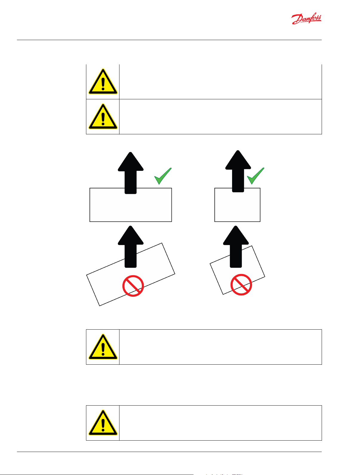
Use correct, adequately dimensioned lifting devices and inspect them before lifting.
Do not apply any excess weight on the electric device when lifting it.
Use correct lifting slings. Use correct position and angle of lifting. The maximum permissible
range of lifting angles is shown in lifting figures.
Make sure that lifting slings are correctly routed so that they do not cause momentum on any
of the signal connectors.
See the rating plate and data sheets for weight information.
©
Danfoss | July 2021 BC265735231757en-000201 | 29
User Guide
EC-C1200-450
Transportation and storage
Lift the electric device using the correct lifting lugs/eyes only. See the lifting Figures in this
Chapter.
Do not go under a lifted load.
Correct lifting and incorrect lifting
Handling
When turning or lifting the electric device, lift it in the air in order to prevent damage to the
frame or other parts of the electric device.
Although the electric device is designed to operate in harsh and demanding environment, any misuse or
improper handling of the electric device is prohibited to avoid malfunctions later.
Storage
When the device is dismounted and stored and packed for delivery, measure that there is no
voltage and then install short circuit wire to the conductor rails to prevent charge from
building up.
30 | © Danfoss | July 2021 BC265735231757en-000201

User Guide
EC-C1200-450
Transportation and storage
Heavy equipment. Store on appropriate base. Support the electric device to prevent
accidental turning and falling.
Do not apply any excess weight on the electric device during storage.
Store the electric device always indoors having the storage temperature preferably above -20 ºC and the
relative humidity less than 60 %. Storage conditions should be dry, dust free and vibration free.
Make sure that the cabling and cooling connections are plugged and sealed before storage.
The electric device must not be subjected to any external vibrations during storage to avoid possible
hidden structural damages.
©
Danfoss | July 2021 BC265735231757en-000201 | 31

User Guide
EC-C1200-450
Installation
Required tools
Risk of electric shock during electrical installations. Use insulated tools..
Following tools are required to install the electric device:
•
Ratchet torque wrench.
•
Hex head wrench kit with different metric sizes.
•
Socket wrench kit with different metric sizes.
•
Cable gland tightening tool. Size according to cable glands.
•
Cable skinning knife.
•
Crimping tool for cable lugs.
For more detailed information, see appropriate Chapters in this user guide and product data sheets at
https://www.danfoss.com.
Mechanical installation
Allowed mounting position
Do not place the electric device on the ground without proper mounting or protective
structure.
The electric device must be mounted on a flat, heat- and flame-resistant mounting place (for example
•
on a bracket).
The electric device can be mounted in any direction. Mount the electric device permanently
•
from the mounting points.
To fulfill the mechanical and environmental standards, for example vibration and shock, it is
•
recommended to mount the electric device from the bottom side, with at least 6 pcs of M8 screws.
Mounting points are shown in the Figure below.
•
32 | © Danfoss | July 2021 BC265735231757en-000201

User Guide
EC-C1200-450
Installation
Location of the mounting points
Selected mounting position must allow the cooling system to work properly. Bleed the air away from the
cooling channels to prevent air pockets.
Make sure that the air vents (2 pcs) are clean and the selected installation place and mounting direction
do not allow water, dust or dirt to block the air vents.
Location of the air vents
©
Danfoss | July 2021 BC265735231757en-000201 | 33

User Guide
EC-C1200-450
Installation
Installation procedure
Risk of electric shock when the connection box lid is open. Make sure that the electric device is
discharged; measure the voltage to make sure of safety.
Do not touch the exposed circuit board under the connection box lid when installing electrical
connections or performing maintenance. An ESD could damage the circuitry.
Heavy electric device. Handle with care. Handle the electric device correctly when you
install it to the correct mounting position. See Chapter Handling on page 30.
Measure the insulation resistance of the electric device before and after the installation of the
electric device.
When installing the connection box lid, make sure there are no foreign particles between the
connection box lid and the insulation and that all connection box fasteners are in place.
Missing or loose screws can compromise the insulation.
Do not use excessive force when installing and removing the X1-connector, the plastic
housing of the X1-connector can break. See the Figure below.
34 | © Danfoss | July 2021 BC265735231757en-000201

User Guide
EC-C1200-450
Installation
Removing the X1-connector
Preparations
Make sure that the chosen installation place fulfills the environmental requirements specified for the
•
electric device.
Protect the electric device against corrosive gases, liquids, conductive contaminants (such as
•
condensation, carbon dust, and metallic particles) and sprays or splashing water from all directions.
Protect the electric device in high humidity, salty or chemical content environments with suitable
•
additional enclosure.
The mounting place and mounting interfaces should be sufficient to carry the weight of the electric
•
device.
Make sure that the electric device has sufficient mounting and operating clearances for maintenance
•
work.
Installation procedure may vary from that shown in this user guide. All steps must be included in the
•
procedure, although the order of the steps can be different.
Installation procedure
1. Prepare the installation place and make sure that it meets the requirements for the product.
2. Lift and support the electrical device for the mounting. Refer to Chapter Lifting on page 29.
3. Install all appropriate mounting screws, do not tighten the screws until they are aligned and preinstalled. See the tightening torques from Chapter Tightening torques on page 28.
4. Connect the cooling system. See Chapter Cooling connections on page 37 or the Main dimension
drawing for connection details. Make sure that there are no air pockets in the cooling channels and that
the coolant goes freely in and out. Make sure that the cooling system operates correctly.
©
Danfoss | July 2021 BC265735231757en-000201 | 35

User Guide
EC-C1200-450
Installation
Cooling system connections
5. Make sure that the devices and machines you will connect to the electric device have no voltage.
6. Make the grounding of the frame of the electric device by direct contact between it and the metal
bracket and / or from the protective earth contacts. The grounding contacts must be paint-free. See
Chapter Grounding on page 43.
7. Uninstall the connector shield (mechanical safety component, sheet metal part).
8. Dismount the connection box lid (power terminal cover).
Connection box lid
9. Connect the power cabling. Refer to Chapter Electrical connections on page 38.
10. Install the connection box lid.
11. Install the connector shield.
12. Connect the X1-connector (control signal connector).
36 | © Danfoss | July 2021 BC265735231757en-000201

User Guide
EC-C1200-450
Installation
X1-connector
Cooling connections
Make sure that cooling liquid runs freely in and out from the electric device.
When selecting cooling liquid nipples, choose nipples that can resist galvanic corrosion.
To prevent damage to the cooling connectors, refer to the documentation of the
manufacturer for the correct tightening torque of the cooling liquid nipples.
Connect the electric device directly to the cooling circuit.
•
Make sure that the coolant flow is equal or higher than rated and the coolant temperature at the inlet
•
of the electric device is lower or equal to the rated temperature.
For more information, see Chapter Recommended coolants on page 38 and product data sheets.
•
Rated values can be found on the rating plate of the electric device.
Coolant connections: 2 x 20mm.
•
It is recommended to fix the hose on the coolant connection with a hose clamp or a hose clip after
•
the protection cap has been removed.
Use water/glycol mix or pure water with corrosion inhibitor as the coolant.
•
It is possible for the electric device to monitor and control the temperatures of the Danfoss PMI family
electric machines. Connect the temperature signal to the temperature monitoring pin of the electric
machine and activate the temperature protection feature.
©
Danfoss | July 2021 BC265735231757en-000201 | 37

User Guide
EC-C1200-450
Installation
Electrical installation
Recommended coolants
Ethylene glycol is a toxic compound. Avoid exposure to the coolant. Handle with care. Use
appropriate personal protective equipment when you handle the coolant.
The electric device works correctly with water based coolant. Plain water with appropriate corrosive
inhibitor is acceptable, for example water with maximum of 50% glycol coolant. Ethylene glycol based
Glysantin® G48® (includes also corrosion inhibitors) or similar can be used. Propylene glycol based
coolants, like Splash® RV&Marine antifreeze, can also be used. Propylene glycol is relatively safe
compound for humans and the environment.
Electrical connections
Before you start the electrical installation make sure that the frame of the electric device is
grounded correctly. Refer to Chapter Grounding on page 43.
Risk of electric shock when power terminal cover is open. When working with the power
connections make sure that electricity has been disconnected and the electric device has
discharged.
Cable lugs are not included in the delivery.
38 | © Danfoss | July 2021 BC265735231757en-000201

2
7
6
5
4
3
User Guide
EC-C1200-450
Installation
Electrical connections
1 X1-connector (Low voltage connector for measurement data and control signals)
2 X2-connector (maintenance connector)
3 DC+
4 DC- / LV5 L3
6 L2
7 L1
©
Danfoss | July 2021 BC265735231757en-000201 | 39

User Guide
EC-C1200-450
Installation
Electrical connections with +CE2 option and +DCE option
1 External connection box
2 L3 connection, external
3 L2 connection, external
4 L1 connection, external
5 DC- connection (+DCE)
6 DC- connection (+DCE)
7 DC+ connection (+DCE)
8 DC+ connection (+DCE)
9 Not in use
10 Not in use
11 Not in use
40 | © Danfoss | July 2021 BC265735231757en-000201

User Guide
EC-C1200-450
Installation
Electrical connections with +CE1 option
1 External connection box
2 DC- connection
3 DC+ connection
4 L3 connection, external
5 L2 connection, external
6 L1 connection, external
7 DC- connection
8 DC+ connection
9 L3 connection
10 L2 connection
11 L1 connection
Use all connections when you install an electric device with +CE1 option. Using only
connections in the connection extension box can cause overheating of the electric device.
Note that +CE1 and +CG6 option combination is an exception where only connections 2 and 3
are in use and connections 7 and 8 are not.
©
Danfoss | July 2021 BC265735231757en-000201 | 41

User Guide
EC-C1200-450
Installation
Electrical connections with +DCE option
Maximum cable lug width and length
EC-C1200-450
Description Converter connection box
Cable lug width max. 17.5 mm
Cable lug length max. 55 mm
Length A 11.5 mm
EC-C1200-450+CE1
Description Converter connection box CE1 connection box
Cable lug width max. 17.5 mm 21 mm
Cable lug length max. 55 mm 60 mm
Length A 11.5 mm 17 mm
EC-C1200-450+CE2
Description Converter connection box (for DC-
link connection only)
Cable lug width max. 17.5 mm 30.5 mm
Cable lug length max. 55 mm 60 mm
Length A 11.5 mm 15 mm
CE2 connection box
42 | © Danfoss | July 2021 BC265735231757en-000201

User Guide
EC-C1200-450
Installation
Cable lug
Grounding
Make sure that the electric device is correctly grounded. Do not operate the electric device
without correctly attached protective earth conductor. Obey the installation instructions and
the guidelines for component selection given in this user guide.
The grounding cable must be able to carry the maximum supply fault current which normally
will be limited by the fuses or the Miniature Circuit Breaker (MCB). Put correctly rated fuses or
MCB in the mains supply of the electrical device: obey the local legislation and
recommendations.
Obey the installation instructions and the guidelines for component selection given in this
user guide.
Make sure that the safety grounding is correct. Refer to Chapter Mechanical installation.
Generic grounding guidelines
•
Connect the ground terminal of each electric device individually to the site grounding bus bar
(through the filter if installed).
•
The grounding connections cannot loop from one electric device to another electric device, or to any
other piece of equipment, or from any other piece of equipment.
•
Ground impedance must be compliant with local industrial safety regulations.
•
The protective ground of the unit must be connected to the system ground. Ground impedance must
meet with the requirements of national and local industrial safety regulations and electrical
requirements. The condition of the grounding connections must be checked periodically.
•
Make sure that all grounding surfaces are clean and remove paint from the contact areas.
•
For detailed information, see appropriate Chapters in this user guide.
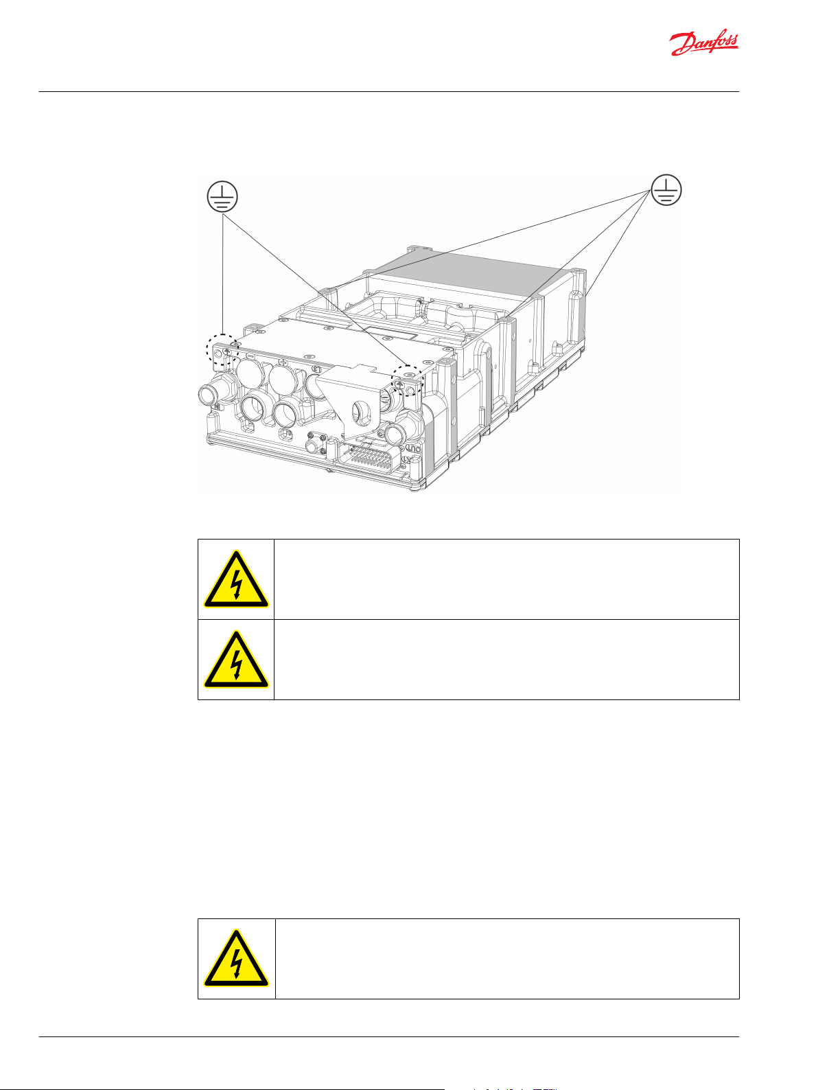
Main frame
The best grounding is achieved when the main frame of each electric device is directly connected to the
ground. If this is not possible, the electric device must be grounded at least from one of the safety
grounding points with an appropriate grounding cable. For good functional grounding use wide flat
grounding braid. Round grounding wires are adequate for safety grounding but it does not provide very
good functional grounding because of its higher impedance at high frequencies. The grounding points
are marked to the electric device.
©
Danfoss | July 2021 BC265735231757en-000201 | 43
User Guide
EC-C1200-450
Installation
Grounding points
Safety grounding points and protective earth conductor
Touch current in the protective earth conductor exceeds 3,5 mA AC and 10 mA DC.
The cross sectional area of the protective earth conductor must be at least equal to that of the
incoming supply conductor.
One of the safety grounding points must be connected to adjacent building steel (girder, joist), a floor
ground rod, or bus bar. Grounding points must comply with national and local industrial safety
regulations and/or electrical codes.
Cabling and wiring
To make sure that the electric device functions correctly and to minimize the radiated emissions, all
connected cables and wires must be EMC-shielded. Shieldings must be connected to the ground at both
ends of the cable or wire. All power connections must be secured with cable lugs and cable glands. EMCshielded cable glands are used in all Danfoss products for the power connections. Make sure that the low
voltage cable (control signal cable) shield is also grounded from the both ends.
Cable gland assembly and power line connection
Risk of electric shock when the connection box lid is not installed.
44 | © Danfoss | July 2021 BC265735231757en-000201
User Guide
EC-C1200-450
Installation
When you work with the power connections make sure that electricity has been disconnected
and the electric device has discharged. Measure the level of the remaining voltage before you
touch the power terminals.
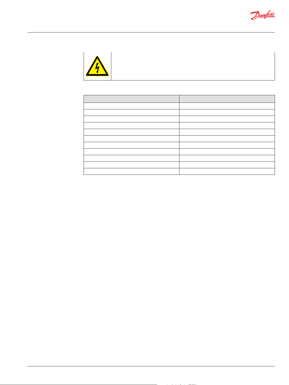
Blueglobe cable gland tightening torques
Metric thread Nominal torque
M10x1,0 3,0 Nm
M12x1,5 5,0 Nm
M16x1,5 8,0 Nm
M20x1,5 10,0 Nm
M25x1,5 15,0 Nm
M32x1,5 15,0 Nm
M40x1,5 20,0 Nm
M50x1,5 30,0 Nm
M63x1,5 35,0 Nm
M75x1,5 80,0 Nm
M85x2,0 100,0 Nm
All electrical connections must be done according to instructions. It is essential to make sure that all
terminal connections are installed properly and the and the intended application is suitable for the
product in terms of electrical requirements/characteristics.
The cable harness for electric connections needs to be terminated with cable lugs and cable glands. It is
recommended to use IP67/68 rated, 360º shielded cable glands and single core automotive rated
screened cable.
The cable gland has three functions, it works as a stress relief, it seals the connection against water and
dirt and provides appropriate EMI shielding. Advanced cable glands could achieve high EMI attenuation
over a wide frequency range.
The cable lug and cable gland must be assembled according to instructions. For correct assembly of the
cable gland, it is recommended to use a torque key with a turnkey head and a key to adapt the cable
gland. The cable lug is connected to terminal with a M8 screw. Shielding of the power cable must be
connected to the electric device body by the cable gland. Recommendations for the tightening torques
must be followed. See the manufacturer's instructions on how to install the cable glands and the cable
lugs. The following instructions may not apply to every type of connection this electric device has.
©
Danfoss | July 2021 BC265735231757en-000201 | 45

User Guide
EC-C1200-450
Installation
Cable harness connection with the cable lug and the cable gland (for illustration only)
Select a cable gland with a thread M25 x 1.5. Make sure that the cable lug can enter through
the M25 threaded hole, Ø 23 mm.
It is recommended to use screw size M8x16 and a washer combination of wave and regular
washers.
Maximum protrusion of the screw through washer and cable lug
Desription
1 Screw
2 Cable lug
3 Cable
4 Washer
46 | © Danfoss | July 2021 BC265735231757en-000201

User Guide
EC-C1200-450
Installation
The information below describes how to assemble screened power cables to the electric device. Pflitsch
BlueGlobe-series cable glands and H+S Radox Elastomer S automotive cables are recommended.
Cable gland assembly instruction can also be found from Pflitsch gland catalogue available from https://
www.pflitsch.de.
Correct cable gland type for the cross section cables is Pflitsch blueglobe TRI bg 225ms tri.
Cable lug and cable gland assembly steps
1. Remove the small hexagonal piece from the BlueGlobe-sealing insert as shown in Figure below.
BlueGlobe-sealing
2. Cut the cable sheath at the distance A from the end of the cable, see Figure below. Pull the cut part of
the sheath partly (length B is from 10 to 15 mm) off the cable as shown in the figure. Distance A depends
of the length of the used cable lug. Measure with the cable lug that is used and cut to suitable length.
Install two layers of copper tape on the cable so that the distance B is covered. Use 3M
Copper Foil Tape 1181 or similar.
Do not remove the cable sheath completely at this point and do not cut the braid screen of
the cable.
™
Cut length of the cable sheath
3. Insert the cable to the cable gland with slight turning motion. This helps the cable go through the
spring inside the cable gland. Push the cable gland against the sheath of the cable as shown in Figure
below.
©
Danfoss | July 2021 BC265735231757en-000201 | 47

User Guide
EC-C1200-450
Installation
Cable to the gland assembly
4. After the cable gland is in place remove the length A piece of the sheath and cut the braid screen
(cover) from 10 mm (distance C) from the gland bottom as shown in Figure below.
Make sure that the cable gland spring is against the cable sheath (that is protected with
copper tape) before cutting the braid screen.
Cut the braid screen
5. Cut a piece of length D of the inner sheath shown in Figure below. The length D must be equal to the
length of the cable lug body.
48 | © Danfoss | July 2021 BC265735231757en-000201

User Guide
EC-C1200-450
Installation
Cutting the inner sheath
6. Make sure that the conducting strands of the cable are completely free of silicone and other impurities.
Place the cable inside the cable lug body, and crimp the cable lug twice in different places. See Figure
below.
Connecting cable lug
7. Cut piece of shrink tube and shrink it over the cable lug and braid screen as shown in Figure below.
This is done to keep the braid screen in place and for extra insulation.
The shrink tube must be specified for operating temperature range from -40 ºC to 150 ºC. Self
gluing shrink tube is recommended.
©
Danfoss | July 2021 BC265735231757en-000201 | 49

User Guide
EC-C1200-450
Installation
Shrink tube
8. Insert the cable through the corresponding hole in the electric device frame and connect the cable lug
to the power terminal with the correct screw. Use spring washer between the cable lug and the
connection screw or nut. Do not tighten the cable lug screw at this point to ensure fitting of the cable
gland.
Make sure that there is at least 10 mm air gap between the cable lug and other metallic
structures including the braid of the cable. If the air gap is smaller, use extra insulation shrink
tube to cover the lug.
9. Screw the cable gland to the power terminals of the electric device according to instructions. Tighten
the cable gland with the specified torque.
Tighten the gable gland from the gable gland body to enclosure with torque 15 Nm. Then
tighten the cap of the gable gland according to the instructions provided by gable gland
manufacturer (recommendation Pflitsch).
10. Tighten the cable lug using the specified torque.
11. Repeat the procedure to the other cables and connections.
12. Close the power terminal cover and install the connector shield.
13. Make sure that the power cable shields are grounded properly.
50 | © Danfoss | July 2021 BC265735231757en-000201

User Guide
EC-C1200-450
Installation
Cable lug and cable gland assembly cross section
Example of the equipment needed for the assembly
Description Manufacturer's homepage Art.No./Part No.
Assembly equipment (example) Torque key and
Assembly example for a 70 mm
cable
Assembly example for a 50 mm
cable
turnkey head
Key http://www.pflitsch.de SE30
2
Cable with nominal
cross-section of 70
2
mm
Cable lug http://www.druseidt.de 10857
Cable gland http://www.pflitsch.de
Screw http://www.wuerth.com DIN 912 M8x16 (item:
Washer http://www.wuerth.com DIN 2093, 8,2 x 16 x 0,9
Washer http://www.wuerth.com
2
Cable with nominal
cross-section of 50
2
mm
Cable lug http://www.druseidt.de 10853
Cable gland http://www.pflitsch.de
Screw http://www.wuerth.com DIN 912 M8x16 (item:
Washer http://www.wuerth.com DIN 2093, 8,2 x 16 x 0,9
Washer http://www.wuerth.com
http://www.pflitsch.de 730N/10-50
http://www.hubersuhner.com Radox Elastomer S
Pflitsch blueglobe TRI bg
225ms tri
10285)
(item: 17332)
DIN 125 D8
(item: 11072)
http://www.hubersuhner.com Radox screened multi core
cable
Pflitsch blueglobe TRI bg
225ms tri
10285)
(item: 17332)
DIN 125 D8
(item: 10285)
©
Danfoss | July 2021 BC265735231757en-000201 | 51

User Guide
EC-C1200-450
Installation
Cabling and wiring
Route the power cables as far from the control signal wires as possible. The minimum
separating distance is 100 mm. The crossings must be in an angle of 90º. Power cables and
control wires should be routed near the frame of the application. Make sure that all terminal
connections are tightened correctly.
If the electric device drives a motor or generator, contact Danfoss if the power cable is longer
than 15 m. For EMC-reasons, a filter might be needed.
Install the electric device by the instructions. Make sure that all the applications of the system, for
example, batteries are connected to the electric device by the instructions of this user guide and the
product specific guidelines.
Cabling
•
For the power cables, it is recommended to use Radox Elastomer S, screened automotive cable or
equivalent cable with similar specifications.
•
Cable cross section can be 35 mm2, 50 mm2, or max. 70 mm2, depending on the maximum current of
the electric device.
•
Use only EMI-shielded power cables to make sure the correct operation of the electric device and to
minimize the radiated emissions. Cable shields must be connected to the electric device ground at
both ends of the cable. All Danfoss products use EMI-shielded cable glands for power connections.
Wiring
To make sure of correct and steady operation, use EMI-shielded cables for the control signals of the
electric device. Cable shields must be connected to the electric device ground at both ends of the cable.
Recommendations for control signal cables
Cable Cable type and properties
Resolver cabling
CAN cabling shielded cable (twisted pair)
Other signals multistrand wire (0.5-1.5 mm2)
External temperature measurement (PT100/PT1000) shielded cable (twisted pair)
User I/O cabling
shielded cable (twisted pair)
shielded cable (twisted pair)
High voltage connections
The high voltage connections have a common ground connector.
U
≥ U
HV
LV
52 | © Danfoss | July 2021 BC265735231757en-000201

User Guide
EC-C1200-450
Installation
Make sure the power cables exit straight from the terminals and do not rub against the sharp
cable through-holes or other sharp edges which could wear out the cable insulation over
time.
Do not place any excess weight on the connection box lid(s).
The electric device must be installed and connected according to the instructions.
•
Make sure that all the connected applications are connected to the electric device according to the
•
product specific operating voltage.
The electric device is delivered with the power terminal cover mounted. To access the power
•
connections, remove the mechanical safety feature and the connection box lid.
DC connection specifications (+MC, +AFE, +UG options)
DC-connection
DC link voltage range 0-850 V
DC link nominal voltage 750 V
DC
DC
AC connection specifications (+MC, +AFE, +UG -options)
AC connection
AC output voltage 0-560 V
EFF (UDC
= 800VDC)
Output frequency 0...580 Hz. Up to 1000 Hz as option.
Switching frequency 8 kHz
Maximum power 300 kVA
AC connection specifications by product type (+MC, +AFE, +UG -options)
AC connection
Option +MC120,
+AFE120, +UG120
+MC180,
+AFE180, +UG180
+MC240,
+AFE240, +UG240
+MC300,
+AFE300, +UG300
+MC350,
+AFE350,
+UG350
Nominal current 120 A
RMS
180 A
RMS
240 A
RMS
300 A
RMS
350 A
Nominal power 100 kVA 150 kVA 200 kVA 250 kVA 300 kVA
High voltage side connection (+DC -option only)
High-voltage side
Voltage range, U
HV
Nominal voltage 750 V
Maximum current 350 A
0-850 V
DC
DC
DC
RMS
Low-voltage side connection by product type, (+DC -option only)
Low-voltage side
Option +DC150 +DC250 +DC300 +DC400
Typical voltage, U
©
Danfoss | July 2021 BC265735231757en-000201 | 53
(*
LV
75-750 V
DC
75-750 V
DC
75-750 V
DC
75-750 V
DC

User Guide
EC-C1200-450
Installation
Low-voltage side connection by product type, (+DC -option only) (continued)
Low-voltage side
Nominal current 150 A
Nominal power
(*
= Maximum transformation ration between LV and HV voltages is 1:10.
(**
= Output power is limited by the LV-side voltage and current. LV-side voltage 600 VDC, HV-side voltage
(**
DC
90 kW 150 kW 200 kW 240 kW
250 A
DC
300 A
DC
400 A
DC
750 VDC.
Product types
Basic product type Nominal power [kVA] Nominal current [A
EC-C1200-450+MC120+AFE120+UG120 100 120
EC-C1200-450+MC180+AFE180+UG180 150 180
EC-C1200-450+MC240+AFE240+UG240 200 240
EC-C1200-450+MC300+AFE300+UG300 250 300
EC-C1200-450+MC350+AFE350+UG350 300 350
RMS
]
For more information, see appropriate chapters in this user guide and the product data sheets.
Low voltage connections
The durability of the X1-connector is limited to 10 installations / removals by the connector
manufacturer.
When powering OFF the electric device, use the POWER_ON input. The power supply (VIN_N
and/or VIN_P) can be disconnected, if desired, after time t
deactivation of POWER_ON (see Figure Disconnecting the power supply in this Chapter). A safe
value for t
See the correct signal connections and product specific pin-layout from product data sheets
at http://www.danfoss.com.
For information about the assembly of the control signal connectors, see the manufacture's
web page.
is 5 seconds.
min
has elapsed from the
min
Control signals (option dependent)
Basic device supports following CAN-protocol:
•
CANopen
•
SAE J-1939
CAN-protocols are alternatives and the choice should be made when placing an order.
The control signals of the electric device are operated with the X1-connector.
To make sure of correct operation of the control signal, use compatible connector interface (male/
female) and appropriate shielded wiring.
54 | © Danfoss | July 2021 BC265735231757en-000201

User Guide
EC-C1200-450
Installation
Control signal connector information
Description Part number Supplier example
X1-Control signal connector (in the chassis)
Tyco Electronics/AMPSEAL, 35-pin (male)
X1-Cable connector (mating connector)
Tyco Electronics/AMPSEAL, 35-pin (female)
1-776163-1 http://www.te.com/usa-en/
Case:776164-1 http://www.te.com/usa-en/
Pins: 770854-3 (wire
0.5-1.25mm2)
product-1-776163-1.html
product-776164-1.html
http://www.te.com/usa-en/
product-770854-3.html
Tools and accessories
Description Part number Supplier example
Crimping Tool Assembly 58529-1 with
Die Assembly 58529-2
Connector seal plug (for storage and
transportation)
35-position wire relief 776463-1 http://www.te.com/usa-en/product-776463-1.html
58529-1 http://fi.mouser.com/ProductDetail/TE-Connectivity/58529-1/?
qs=Xf%252b3Aw93yEM%2FQReWIgzu%252bw%3D
%3Dhttp://fi.mouser.com/ProductDetail/TE-Connectivity/
58529-1/?qs=Xf%252b3Aw93yEM%2FQReWIgzu%252bw%3D
%3D
770678-1 http://www.te.com/usa-en/product-770678-1.html
Detailed and up to date information can be found at manufacturer's web-pages. Connector assembly
according to connector manufacturer instructions (for example contact crimping).
Minimum wiring and connections needed for powering the electric device are shown below (marked
with red). If any of these signals is not connected, the electric device will not be switched on or it will be
in the tripped state and will not work.
©
Danfoss | July 2021 BC265735231757en-000201 | 55

User Guide
EC-C1200-450
Installation
Low voltage signals: minimum connections needed for powering the electric device
Minimum wiring and connections
Pin Signal name Description
13 VIN_N Power supply negative
1 VIN_P Power supply positive (continuous). Typically 12-24 V, see data sheets.
2 POWER_ON Power supply positive (from on/off key). Typically the same voltage as VIN_P.
24 STOP_1 Stop input 1. Needs to be pulled up (same range as VIN_P) for the converter to run.
Disconnecting the STOP input or pulling it low externally causes the power semiconductor
switch drivers to be disabled, which makes the converter a diode bridge. Stopping the converter
with one of the STOP inputs causes also a fault, which needs to be cleared before continuing
operation.
3 STOP_2 Stop input 2. Identical to stop input 1. Both need to be pulled up in order to be able to run.
A minimal wiring scheme is shown in the figure below. The main point is that the POWER_ON input is the
one that should be used to turn the electric device ON or OFF. In particular, shut-down by
disconnecting VIN_N or VIN_P may in some circumstances result in the corruption of the parameters of
the electric device or other data.
56 | © Danfoss | July 2021 BC265735231757en-000201

User Guide
EC-C1200-450
Installation
Example of the minimum connections
The switch (SW1) is used to turn the converter on and off. VIN_P and VIN_N are continuously connected
to the power supply. There is an internal pull-down in the POWER_ON input. Use appropriate fuse (F1) for
protection. See values and information for fuse selection from the product data sheets.
Disconnecting the power supply
Sufficient time should elapse between bringing the POWER_ON voltage down and bringing VIN_P down.
Use of the grounding pins
In addition to the aforementioned signals, there are various ground (GND) pins in the signal connector.
CAN and I/O features use separate GND pins. The difference between unisolated GND pins and VIN_N is
that VIN_N/VIN_P go through a common mode choke for the filtering of conducted
emissions. Connecting signal GND and VIN_N together effectively disables the common mode choke.
POWER_ON and STOP signals use device internal GND as their reference. If, externally, they are produced
with respect to VIN_N, a high level of common mode disturbance may throw POWER_ON and STOPs out
of their operating range and cause the converter to stop or reboot. This can be fixed by connecting
VIN_N and signal GND, but this comes at the cost of increased EMI. Finally, there is an enclosure ground
pin, which is connected to the enclosure (frame) of the converter and can be used to connect cable
shields.
General information
Connect VIN_P to the positive power supply and VIN_N to the negative power supply. POWER_ON and
STOP_1/STOP_2 are usually connected to positive power supply. If STOP signals are used connect the
emergency stop switch between the STOP and positive power supply.
STOP signal should go high at the same time or before the power supply is connected to VIN_P and
VIN_N. If STOP signals are connected after VIN_P and VIN_N the inverter will most likely register the STOP
as active and be in emergency stop trip state. If this happens the wiring can be changed connecting the
power supply to VIN_P and VIN_N at same time or before the STOP signals. The emergency state trip can
also be cleared after every startup of the electric device.
©
Danfoss | July 2021 BC265735231757en-000201 | 57

User Guide
EC-C1200-450
Installation
CAN-network should be done using twisted pair shielded cable to minimize EMI for the CAN signals. It is
recommended to not use the shield of the CAN cable as the CAN ground, but to use a separate ground
wire.
CAN grounding
If PT100/1000 temperature inputs are used, use signal ground as the ground connection for the sensor.
Motor overload protection
The electric device has three PT100/1000 external temperature sensor inputs that can be used to protect
the motor from overheating. These inputs can be configured to derate the motor current linearly
between two temperatures. For example derate could start when motor temperature is 130°C and
linearly derate the motor current as motor heats and the maximum derate could be at 150°C. Additionally
there are three configurable temperature levels that can cause different actions. First level is note, second
is warning and third is fault. Note can only be seen in fault log of the device. Warning can be seen as CANmessage as well as in fault log. Fault will trip the device stopping all operation and will also show as CAN
message and in fault log.
In addition to the temperature surveillance that can be used the device has over current and short circuit
protection that stops the device if short circuit or over current is detected.
Signals for monitoring, diagnostics and set-up
The electric device can be connected to the USB-port of the PC with the maintenance connector (USB to
RS485). Maintenance connector enables monitoring, diagnostics and setting up of the electric device. By
using the PowerUSER application, it enables these functions via remote access, for example in the case of
problem solving.
Reliable connection between the PC and the electric device can be ensured by using the Power Series
Service Cable (PSSC). The PSSC is isolated RS485 and shielded cable, designed for demanding
environments. The cable is available in 3 meter (PSSC-3M) and 10 meter version (PSSC-10M). Same cable
can be used with all Danfoss products that have a service connector.
The service cable is ordered separately, see Chapter Service parts on page 69 for ordering details.
PowerUSER application can be downloaded for free from http://www.danfoss.com/.
58 | © Danfoss | July 2021 BC265735231757en-000201

User Guide
EC-C1200-450
Installation
Maintenance connector
©
Danfoss | July 2021 BC265735231757en-000201 | 59

User Guide
EC-C1200-450
Operation
Operation conditions
The electric device should be used for its intended purpose only and within limits specified by the
manufacturer, concerning:
Loading.
•
Cooling.
•
Service interval.
•
Ambient conditions such as temperature and moisture.
•
The electric device is designed for these conditions:
Ambient temperature limits: -40 °C...105 °C.
•
Maximum altitude 2000 m above sea level.
•
Maximum coolant liquid temperature at the inlet of the coolant circuit, see product data sheets.
•
Coolant liquid must be water-glycol mixture with maximum of 50 % glycol content. See Chapter
•
Recommended coolants on page 38.
The electric device must be pre-charged, see Chapter Pre-charging on page 60.
If the operation limits are exceeded and the electric device is damaged, please contact local Danfoss
representative.
Pre-charging
Do the pre-charging correctly, or the high inrush current may break external electrical
components of the electric device.
The electric device DC-link capacitance can be found from the data sheet.
Devices with DC-link capacitance should be pre-charged before connecting them to battery,
supercapacitor or charged DC-link. Pre-charging is needed to limit the inrush current that would happen,
if the capacitors are not pre-charged. Pre-charging can be done by using pre-charge resistor and
contactor before the DC-link is connected to battery, supercapacitor or to another DC-link that has
different voltage. After pre-charging, the safe voltage difference between two potentials is 5-10 volts.
The Figure below shows the principle of pre-charging. C2 is pre-charged from a high voltage
battery through K1, K3 and R.
60 | © Danfoss | July 2021 BC265735231757en-000201

User Guide
EC-C1200-450
Operation
Principle of pre-charging
Condition monitoring during operation
Monitor the electric device regularly during operation to make sure of reliable operation, to foresee
possible upcoming failures and to help to reach the designed lifetime of the product.
Risk of permanent damage to the electric device. Use the electric device only in the ambient
conditions given in this user guide and in the data sheet.
Risk of permanent damage to the electric device. Use the electric device only if the technical
guidelines given in this user guide and in the data sheet are met.
Risk of permanent damage to the electric device. If you notice deviations from the normal
operation (for example: high temperatures or noise), stop the electric device. Find the reason
for the deviation and take action to repair the functionality of the electric device. Refer to
Chapter Troubleshooting on page 67 for more information.
©
Danfoss | July 2021 BC265735231757en-000201 | 61

User Guide
EC-C1200-450
Maintenance
Regular maintenance
Do not disassemble the electric device. You can do only procedures described in this user
guide. For further information contact Danfoss representative.
Only trained and qualified personnel that are familiar with the relevant safety requirements
can do any maintenance to the electric device.
Risk of electric shock when the connection box lid is removed.
Inspect the electric device at regular intervals. Use the regular maintenance checklists in the
inspections.
Do not attempt to tighten or release any screws, nuts or joints which are not shown in this
user guide and that are not involved in the normal installation and maintenance procedures.
Use correct personal protective equipment when you are near the electric device.
Read the instructions in the user guide before you install the electric device. To make sure of
safe and reliable operation of the electric device, obey the maintenance instructions.
62 | © Danfoss | July 2021 BC265735231757en-000201

User Guide
EC-C1200-450
Maintenance
Maintenance intervals
Object Check/Task Weekly Monthly Yearly
General
construction
Electrical system Cables Visual check, for example wear. Replace if
Cooling system Operation Functioning. Cooling system functions as
Operation Abnormal phenomenon, for example noise or
Mounting Tightness of the screws. Tighten to proper
Enclosure and
connected parts
Electrical
connections
Groundings
(earthings)
Tubing and
connection
tightness
Ventilation plug Cleanliness. Clean if necessary. See Chapter
Coolant quality Use the coolant as specified (proper glycol and
heating. If clearly increased, contact Danfoss
representative.
value if necessary. Applies to screws that are
presented in this user guide. See Chapter
Tightening torques on page 28.
Check cleanliness. Clean if necessary. See
Chapter Cleaning on page 63.
necessary.
Check connections. Ensure that sufficient
tightening torque is applied to cable glands.
See Chapter Tightening torques on page 28.
Check groundings (earthings). Ensure that the
connection resistance is valid. Re-connect if
necessary.
specified.
No visible leakage. If leaking, tighten
connections appropriately, or replace parts.
Cleaning on page 63.
water/glycol mixture appropriate). Refill if
necessary. See Chapter Cooling system
maintenance on page 63.
X
X
X
X
X
X
X
X
X
X
Cooling system maintenance
Cleaning
The cooling system of the electric device requires regular observation and maintenance
activities. Observe weekly that the cooling system operates correctly and check monthly that there are no
leakages in the cooling system. The quality of the coolant must be checked yearly. The mixture of water
and glycol as well as the type of the glycol used must be as specified. See Chapter Recommended coolants
on page 38.
Do not use pressure washer for cleaning. High water pressure may damage the gaskets
allowing water to go in to the electric device.
Never open or remove the watertight ventilation plugs. Clean them only from the outside.
Risk of electric shock if the electric device is cleaned against instructions allowing water to go
in to the electric device.
©
Danfoss | July 2021 BC265735231757en-000201 | 63

User Guide
EC-C1200-450
Maintenance
Keep the electric device clean. For cleaning, use non-abrasive and non-corrosive cleaning products. Make
sure that the detergent can be used for aluminum.
64 | © Danfoss | July 2021 BC265735231757en-000201

User Guide
EC-C1200-450
Dismounting and disposal of the electric device
Risk of electric shock if dismounting steps are continued before the electric device is
discharged and a safe voltage level has been measured.
Do not touch the electric device or continue to work with the electric device until it cools
down.
Do not use excessive force when you disconnect the connector, because the plastic housing of
the connector can break. Release the retaining clip of the connector before you disconnect
the connector.
Do not try to unplug the X1, X2 or X3 connectors by pulling from their wires.
Support the electric device during dismounting, handle it with care.
When the device is dismounted and stored and packed for delivery, measure that there is no
voltage and then install short circuit wire to the conductor rails to prevent charge from
building up.
Refer to Chapter Installation procedure on page 34 for additional information.
Dismounting procedure
1. Switch off the electric device.
2. Make sure that the cooling system remains operational.
3. Release the retaining clip of the X1-connector (control signal connector, low voltage, 35-pin) and
disconnect the connector.
4. Wait until the electric device has fully discharged. Always measure that no voltage is present on the
power terminals before you proceed.
5. Wait until the temperature of the electric device and cooling liquid has decreased below +40 oC.
6. Remove the mounting screws and dismount the electric device from the mounting base.
7. Dismount the connector shield (mechanical safety component).
8. Dismount the connection box lid (power terminal cover).
9. Disconnect the power terminal cabling and the grounding cables (protective earth).
10. Disconnect the liquid cooling system.
11. Install the connection box lid and other parts and plug all electrical and cooling connections for
longer storage.
12. Lift off the electric device according to Chapter Lifting on page 29.
©
Danfoss | July 2021 BC265735231757en-000201 | 65

User Guide
EC-C1200-450
Dismounting and disposal of the electric device
Disposal of the electric device
Dispose of the electric device and any of its parts by local laws and regulations.
66 | © Danfoss | July 2021 BC265735231757en-000201
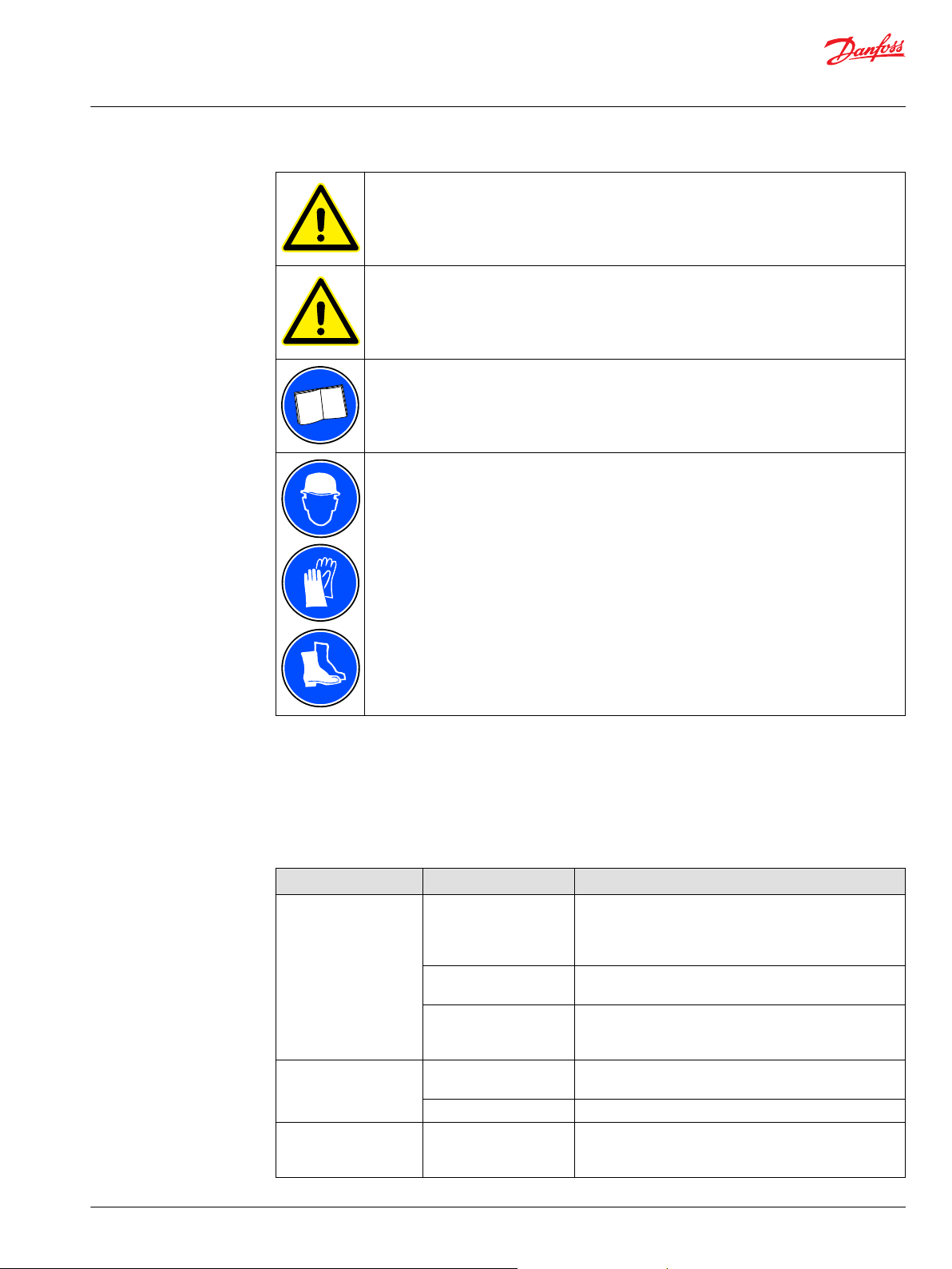
User Guide
EC-C1200-450
Troubleshooting
Do not activate the automatic fault reset function on any system where it can be the cause of a
potentially dangerous situation.
Do not try to repair the electric device. In the case of suspected fault or malfunction, contact
Danfoss or authorized service centre for further assistance.
For the reason of general safety and correct operative actions, read the instructions carefully
before you start any analyses or work with the electric device.
Use correct personal protective equipment when you are near the electric device.
Some unexpected situations may occur while operating the electric device. Some of the possible causes
and actions are given in table below. If an unexpected situation occurs, it should be corrected as soon as
possible.
These instructions do not cover all details or variations in the equipment nor provide information for
every possible condition to be met in connection with installation, operation or maintenance.
Troubleshooting
Fault description Possible cause Action
Electric device
overheating
Significant coolant leak Loose connection in the
Electric device does not
work correctly or the
performance is poor
Cooling system failure. Inspect the cooling system operation and functionality,
especially possible leaks, flow rate and fluid temperature.
Change the cooling flow direction to flush the cooling
system from sediment possibly accumulated.
Leakage in the cooling
system.
Rigid particle inside the
cooling channel of the
electric device.
coolingsystem.
Broken cooling hose. Replace the cooling hose.
Poor powerline contacts
(high voltage)
Inspect the cooling system circuit and connections.
Try to pulsate coolant to open the channels.
Contact Danfoss representative.
Inspect, clean and tighten the connections. Replace them if
neccessary.
Inspect, clean and tighten the contacts.
©
Danfoss | July 2021 BC265735231757en-000201 | 67

User Guide
EC-C1200-450
Troubleshooting
Fault history and fault reset (+CAN option only)
When an unusual operating condition is detected by the control diagnostics, the electric device gives a
notification. The notifications vary depending on the consequences and required action:
Fault- type of notification stops the electric device and requires reset.
•
Warning- type of notification informs of unusual operating conditions, but the electric device stays
•
operative (power on).
When a fault appears and stops the electric device, the root cause of the fault must be defined before any
further actions. All faults are stored in to Fault history- menu.
After the root cause is defined and the electric device is inspected and recovered according to
instructions, the fault can be reset. Fault resetting can be done with the reset signal through the fieldbus
or by using maintenance connection and PowerUSER application.
For more information about the fault history and fault reset, see product data sheets.
68 | © Danfoss | July 2021 BC265735231757en-000201

User Guide
EC-C1200-450
Aftersales
Service policy
Service parts
Maintenance and service of the electric device is limited to the procedures described in this user guide.
See Chapter Service parts on page 69 below for available service and accessory parts. For further
information, contact Danfoss representative.
The recommended service parts are listed in the Table below. Contact Danfoss representative for more
information and purchasing.
Service parts with standard connections
Service parts
Position if
shown
1 10756 1 Connector shield. Mechanical safety
2 10348 5 Cable glands Pflitsch blueglobe TRI bg
3 10988 1 Service connector cap. Binder series: 713, P/N
4 X
(*
= Use description for ordering
©
Danfoss | July 2021 BC265735231757en-000201 | 69
Item / order
number
(*
Quantity Description Type
feature, which prevents opening the
connection box if the signal
connector is not disconnected.
1 Connection box lid (power terminal
cover).
-
225ms tri
082616000000
-

User Guide
EC-C1200-450
Aftersales
Service parts, +DCE option
Service parts, +DCE option
Position if
shown
1 10756 1 Connector shield. Mechanical safety
2 10348 7 Cable glands. Pflitsch blueglobe TRI bg
3 10988 1 Service connector cap. Binder series: 713, P/N
4 X
- 13231 1 Spacer sleeve kit (includes 2 pcs of cable
(*
= Use description for ordering
Item / order
number
(*
Quantity Description Type
feature, which prevents opening the
connection box if the signal connector is
not disconnected.
1 Connection box lid (power terminal
cover).
glands, 2pcs spacers and necessary
screws and washers) for double DC-link
connection (+DCE-option).
-
225ms tri
082616000000
-
-
70 | © Danfoss | July 2021 BC265735231757en-000201

User Guide
EC-C1200-450
Aftersales
Service parts, +CE1 option
Position if
shown
1 10756 1 Connector shield. Mechanical safety
2 10348 10 Cable glands. Pflitsch blueglobe TRI bg
3 10988 1 Service connector cap. Binder series: 713, P/N
4 X
(*
= Use description for ordering
Item / order
number
(*
Quantity Description Type
feature, which prevents opening the
connection box if the signal
connector is not disconnected.
225ms tri
082616000000
1 Connection box. -
©
Danfoss | July 2021 BC265735231757en-000201 | 71

User Guide
EC-C1200-450
Aftersales
Service parts, +CE2 option
Service parts, +CE2 option
Position if
shown
1 10756 1 Connector shield. Mechanical
2 10348 2 Cable glands Pflitsch blueglobe TRI bg
3 10988 1 Service connector cap. Binder series: 713, P/N
4 X
5 16871 3 Cable glands. Pflitsch blueglobe TRI bg
(*
= Use description for ordering
Item / order
number
(*
Quantity Description Type
safety feature, which prevents
opening the connection box if
the signal connector is not
disconnected.
225ms tri
082616000000
1 Connection box. -
232ms tri
Accessory spare parts
Item / order number Quantity Description Type
11131 1 Connection cable between PC and EC-C (USB to RS485), 3 meter serial
cable.
11132 1 Connection cable between PC and EC-C (USB to RS485), 10 meter
serial cable.
PSSC-3M
PSSC-10M
72 | © Danfoss | July 2021 BC265735231757en-000201

Danfoss
Power Solutions GmbH & Co. OHG
Krokamp 35
D-24539 Neumünster, Germany
Phone: +49 4321 871 0
Danfoss
Power Solutions ApS
Nordborgvej 81
DK-6430 Nordborg, Denmark
Phone: +45 7488 2222
Danfoss
Power Solutions (US) Company
2800 East 13th Street
Ames, IA 50010, USA
Phone: +1 515 239 6000
Danfoss
Power Solutions Trading
(Shanghai) Co., Ltd.
Building #22, No. 1000 Jin Hai Rd
Jin Qiao, Pudong New District
Shanghai, China 201206
Phone: +86 21 2080 6201
Products we offer:
Hydro-Gear
www.hydro-gear.com
Daikin-Sauer-Danfoss
www.daikin-sauer-danfoss.com
Cartridge valves
•
DCV directional control
•
valves
Electric converters
•
Electric machines
•
Electric motors
•
Gear motors
•
Gear pumps
•
Hydraulic integrated
•
circuits (HICs)
Hydrostatic motors
•
Hydrostatic pumps
•
Orbital motors
•
PLUS+1® controllers
•
PLUS+1® displays
•
PLUS+1® joysticks and
•
pedals
PLUS+1® operator
•
interfaces
PLUS+1® sensors
•
PLUS+1® software
•
PLUS+1® software services,
•
support and training
Position controls and
•
sensors
PVG proportional valves
•
Steering components and
•
systems
Telematics
•
Danfoss Power Solutions is a global manufacturer and supplier of high-quality hydraulic and
electric components. We specialize in providing state-of-the-art technology and solutions
that excel in the harsh operating conditions of the mobile off-highway market as well as the
marine sector. Building on our extensive applications expertise, we work closely with you to
ensure exceptional performance for a broad range of applications. We help you and other
customers around the world speed up system development, reduce costs and bring vehicles
and vessels to market faster.
Danfoss Power Solutions – your strongest partner in mobile hydraulics and mobile
electrification.
Go to www.danfoss.com for further product information.
We offer you expert worldwide support for ensuring the best possible solutions for
outstanding performance. And with an extensive network of Global Service Partners, we also
provide you with comprehensive global service for all of our components.
Local address:
Danfoss can accept no responsibility for possible errors in catalogues, brochures and other printed material. Danfoss reserves the right to alter its products without notice. This also applies to products
already on order provided that such alterations can be made without subsequent changes being necessary in specifications already agreed.
All trademarks in this material are property of the respective companies. Danfoss and the Danfoss logotype are trademarks of Danfoss A/S. All rights reserved.
©
Danfoss | July 2021 BC265735231757en-000201
 Loading...