

Page 1
OperatingGuide
ECA30/31forECLComfort210/210B/296/310/
310B
1.0TableofContents
1.0TableofContents.............................................1
2.0UserGuide.......................................................2
2.1Symboloverview..................................................2
2.2Introduction........................................................4
2.3DisplayinformationECA30/31.................................5
2.4OverridefunctionsECA30/31..................................10
3.0Installation......................................................11
3.1Importantsafetyandproductinformation....................11
3.2Mounting...........................................................15
3.3Placingthetemperaturesensors................................16
3.4Electricalconnections.............................................17
3.5ECA30/31setupprocedures...................................20
4.0Settings...........................................................28
4.1Roomtemperature................................................28
4.2Optimization........................................................29
4.3Holiday..............................................................30
©Danfoss|2021.05AQ089886456757en-010401|1
Page 2

ECA30/31forECLComfort210/210B/296/310/310B
2.0UserGuide
2.1Symboloverview
2|©Danfoss|2021.05
AQ089886456757en-010401
Page 3
ECA30/31forECLComfort210/210B/296/310/310B
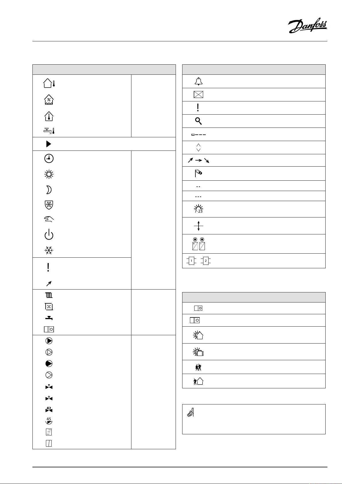
2.1.1Ageneraloverview:Whatdothesymbolsmean?
Symbol
Description
Outdoortemp.
Relativehumidityindoor
Roomtemp.
DHWtemp.
Positionindicator
Scheduledmode
Comfortmode
Savingmode
Frostprotectionmode
Manualmode
Standby
Coolingmode
Symbol
Temperature
Mode
Description
Alarm
Letter
Event
Monitoringtemperaturesensor
connection
Displayselector
Max.andmin.value
Trendinoutdoortemperature
Windspeedsensor
Sensornotconnectedornotused
Sensorconnectionshort-circuited
Fixedcomfortday(holiday)
Activeinfluence
Heatingactive(+)
Coolingactive(-)
Activeoutputoverride
Optimizedstartorstoptime
Heating
Cooling
DHW
Commoncontrollersettings
PumpON
PumpOFF
FanON
FanOFF
Actuatoropens
Actuatorcloses
Actuator,analoguecontrol
signal
Pump/fanspeed
DamperON
Circuit
Controlled
component
Numberofheatexchangers
Additionalsymbols,ECA30/31:
Symbol
InECA30/31onlythesymbolsthatarerelevanttotheapplicationin
thecontrolleraredisplayed.
Description
ECARemoteControlUnit
Connectionaddress(master:15,slaves:1-9)
15
Dayoff
Holiday
Relaxing(extendedcomfortperiod)
Goingout(extendedsavingperiod)
DamperOFF
AQ089886456757en-010401
©Danfoss|2021.05|3
Page 4
ECA30/31forECLComfort210/210B/296/310/310B
2.2Introduction
TheRemoteControlUnits(RCU)ECA30andECA31areusedfor
roomtemperaturecontrolandoverrideoftheECLComfort210/
210B,ECLComfort296andECLComfort310/310Bcontrollers.
UptotworemotecontrolunitscanbeconnectedtooneECL
controllerinordertocontroltheECLcontrollerremotely.
Thedisplayhasbacklight.
TheRCUsareconnectedtotheECLComfortcontrollersbymeans
of2×twistedpaircablesforcommunicationandpowersupply
(ECL485communicationbus).
TheECA30/31hasabuilt-inroomtemperaturesensor.An
externalroomtemperaturesensorcanbeconnectedsubstituting
thebuilt-intemperaturesensor.
Furthermore,theECA31hasabuilt-inrelativehumiditysensorand
thesignalisusedinrelevantapplications.
Itispossibletoconnectupto2RCUsontheECL485
communicationbus.
OneRCUcanmonitormax.10ECLComfortcontrollers(master/
slavesystem).
Pleaseconsulttheuserguidethatisenclosedwithyourproductfor
moreinformationontheECLComfortcontroller.
ECA30
(codeno.087H3200)
ECA31
(codeno.087H3201)
Remotecontrolunitwithroom
temperaturesensor
Remotecontrolunitwithroom
temperaturesensorandrelative
humiditysensor
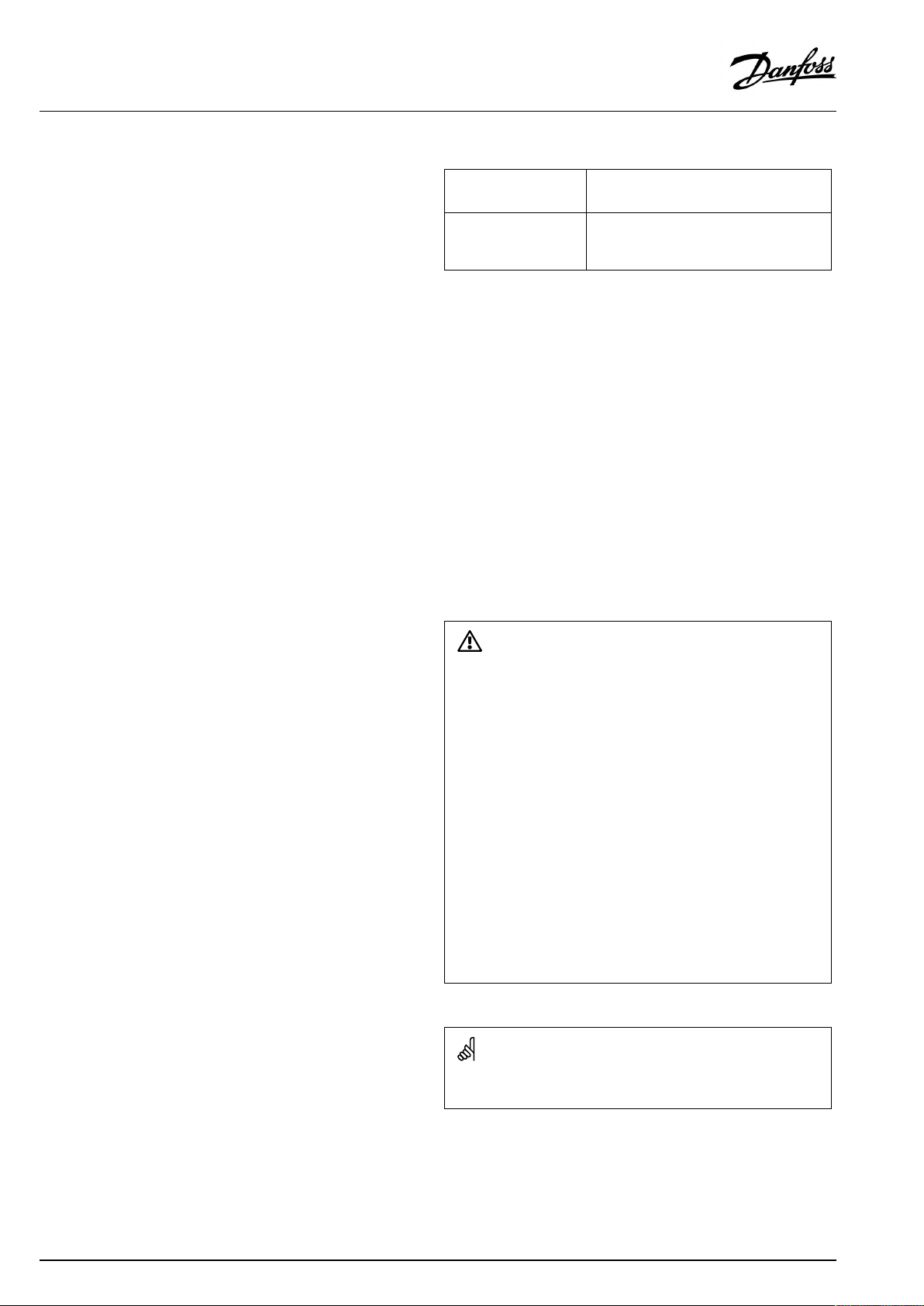
SafetyNote
Toavoidinjuryofpersonsanddamagestothedevice,itisabsolutely
necessarytoreadandobservetheseinstructionscarefully.
Necessaryassembly,start-up,andmaintenanceworkmustbe
performedbyqualifiedandauthorizedpersonnelonly.
Locallegislationsmustberespected.Thiscomprisesalsocable
dimensionsandtypeofisolation(doubleisolatedat230V).
AfusefortheECLComfortinstallationismax.10Atypically.
TheambienttemperaturerangesforECLComfortinoperationare:
ECLComfort210/310:0-55°C
ECLComfort296:0-45°C.
Exceedingthetemperaturerangecanresultinmalfunctions.
Installationmustbeavoidedifthereisariskforcondensation(dew).
Thewarningsignisusedtoemphasizespecialconditionsthatshould
betakenintoconsideration.
Thissymbolindicatesthatthisparticularpieceofinformationshould
bereadwithspecialattention.
4|©Danfoss|2021.05
AQ089886456757en-010401
Page 5
ECA30/31forECLComfort210/210B/296/310/310B
2.3DisplayinformationECA30/31
2.3.1Howtonavigate
ThedisplayandthedialareusedinthesamewayasintheECL
ComfortController.
Younavigateinthecontrollerbyturningthedialleftorrightto
thedesiredposition().
Thedialhasabuilt-inaccellerator.Thefasteryouturnthedial,the
fasteritreachesthelimitsofanywidesettingrange.
Thepositionindicatorinthedisplay(
)willalwaysshowyouwhere
youare.
Pushthedialtoconfirmyourchoices().
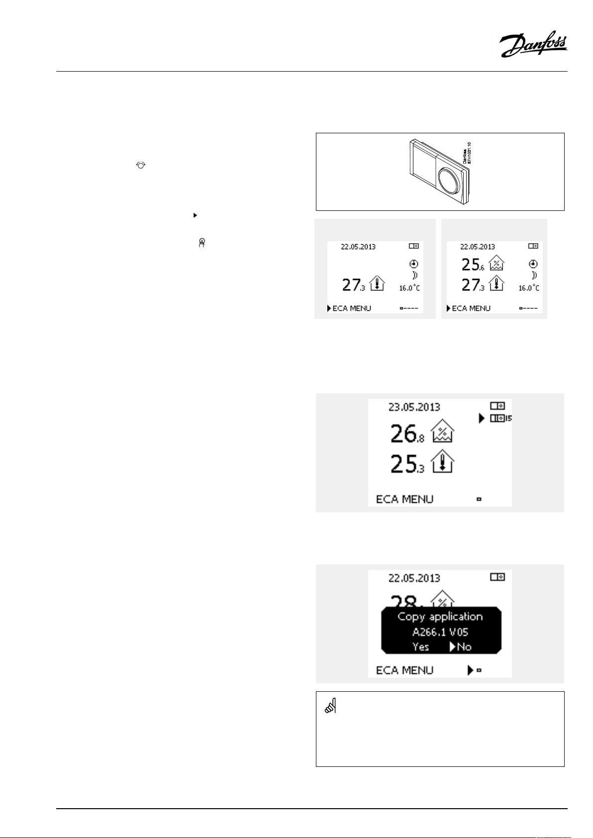
ThedisplayexamplesarefromanECA30andanECA31.
Theexamplesmightdifferfromyourapplication.
2.3.2ECA30/31,displayinformation
ThecontrollericonhasanaddressindicationoftheconnectedECL
Comfortcontroller.
Tochangeconnectionaddress:
1.ChooseECApicture
2.Movethepositionindicatortothecontrollericon
3.Pushthedialtoselectthecontrollericon
4.Turnthedialtoselectdesiredaddress
5.Pushthedialtoconfirmyourchoice
ECA30:ECA31:
ExampleshowingconnectedECLComfortControlleraddress.
2.3.3Pop-up:Copynewapplication,YES/NO
ThefirsttimeanECA30/31connectstoanECLComfort
controllerwithanewapplicationoraknownapplicationwitha
newlanguage,theECA30/31askstocopytheapplicationand
languagetotheECA30/31.
Propercommunicationisnotpossiblebeforetheapplicationhas
beencopied.
NO:TheapplicationwillnotbecopiedtotheECA30/31.
YES:TheapplicationwillbecopiedtotheECA30/31.
Typically,theselectionis"YES" .
"NO"isselectedwhensomeofseveralECLComfortcontrollersin
anECL485bussystemshouldnotbecopiedtotheECA30/31.
AQ089886456757en-010401
WhenstartingtheECA30/31forthefirsttime,thereactiontime
seemsslow.
Normalreactiontimeisachievedwhentheapplicationhasbeen
copiedtotheECA30/31.
©Danfoss|2021.05|5
Page 6
ECA30/31forECLComfort210/210B/296/310/310B
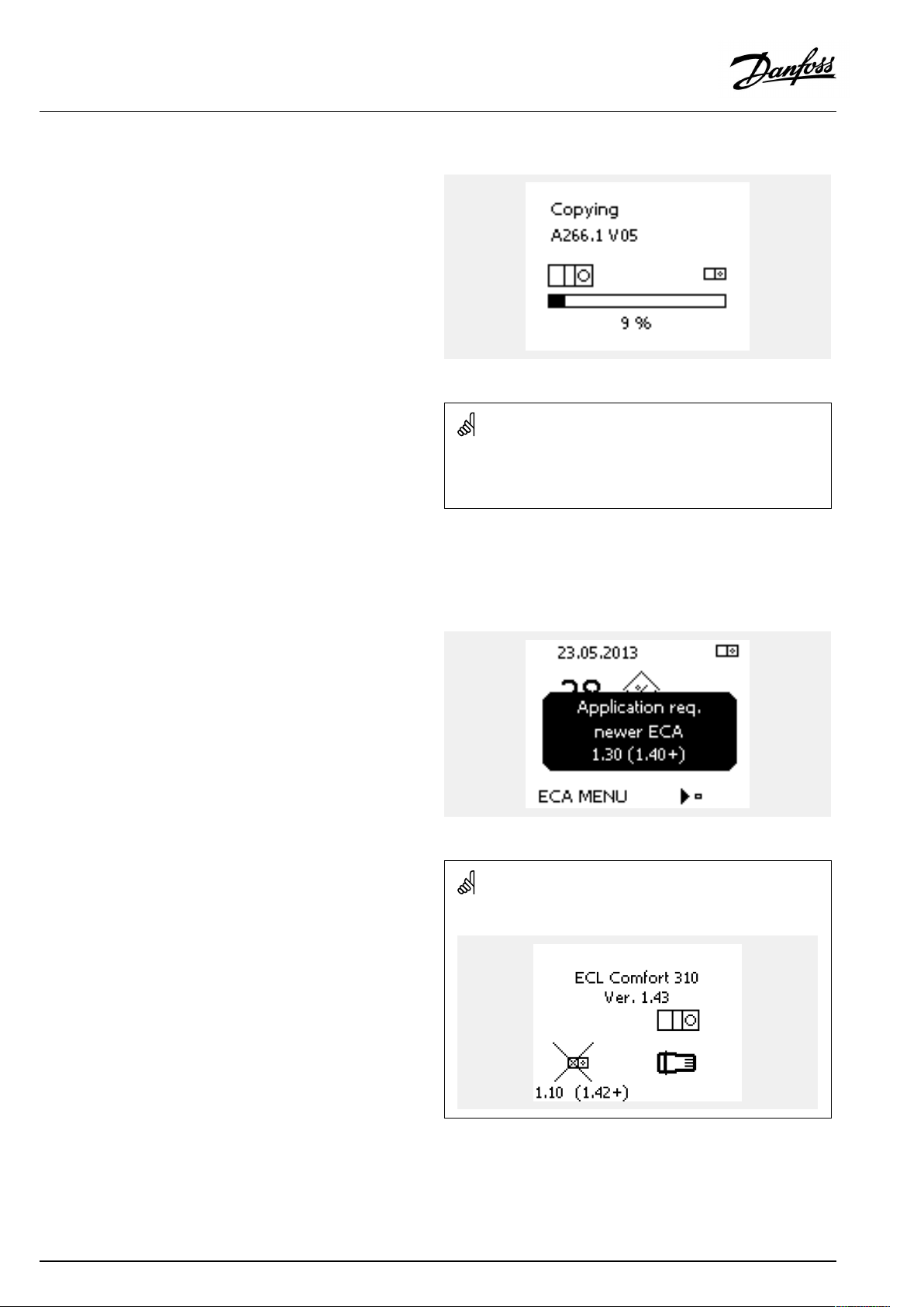
2.3.4Situation:Copying
Theapplication,forexampleA266.1,iscopiedtotheECA30/31.
ThecopiedapplicationissavedintheECA30/31.Herebythe
applicationdoesnotneedtobecopiedagainthenexttimetheECA
30/31connectstothesameECLComfortcontroller .
Upto10applicationscanbesaved.
2.3.5Pop-up:ApplicationrequiresnewerECA
Thispop-upmessageindicatesthattheapplicationcannotrunin
theECA30/31becausenewimprovementshavebeenmade.
AnECA30/31musthavetheversion1.39asaminimuminorder
tobeupdatedfromanapplicationkey.
Situation:
TheECA30/31willdisplaythisinformation(anXontheECA30/
31symbol)iftheapplicationintheECLcontrollerdoesnotcomply
withtheECA30/31.
Inthisexample1.30iscurrentversionand1.40ornewerisdesired
version.
Inthisexample1.10iscurrentversionand1.42isdesiredversion.
6|©Danfoss|2021.05
AQ089886456757en-010401
Page 7
ECA30/31forECLComfort210/210B/296/310/310B
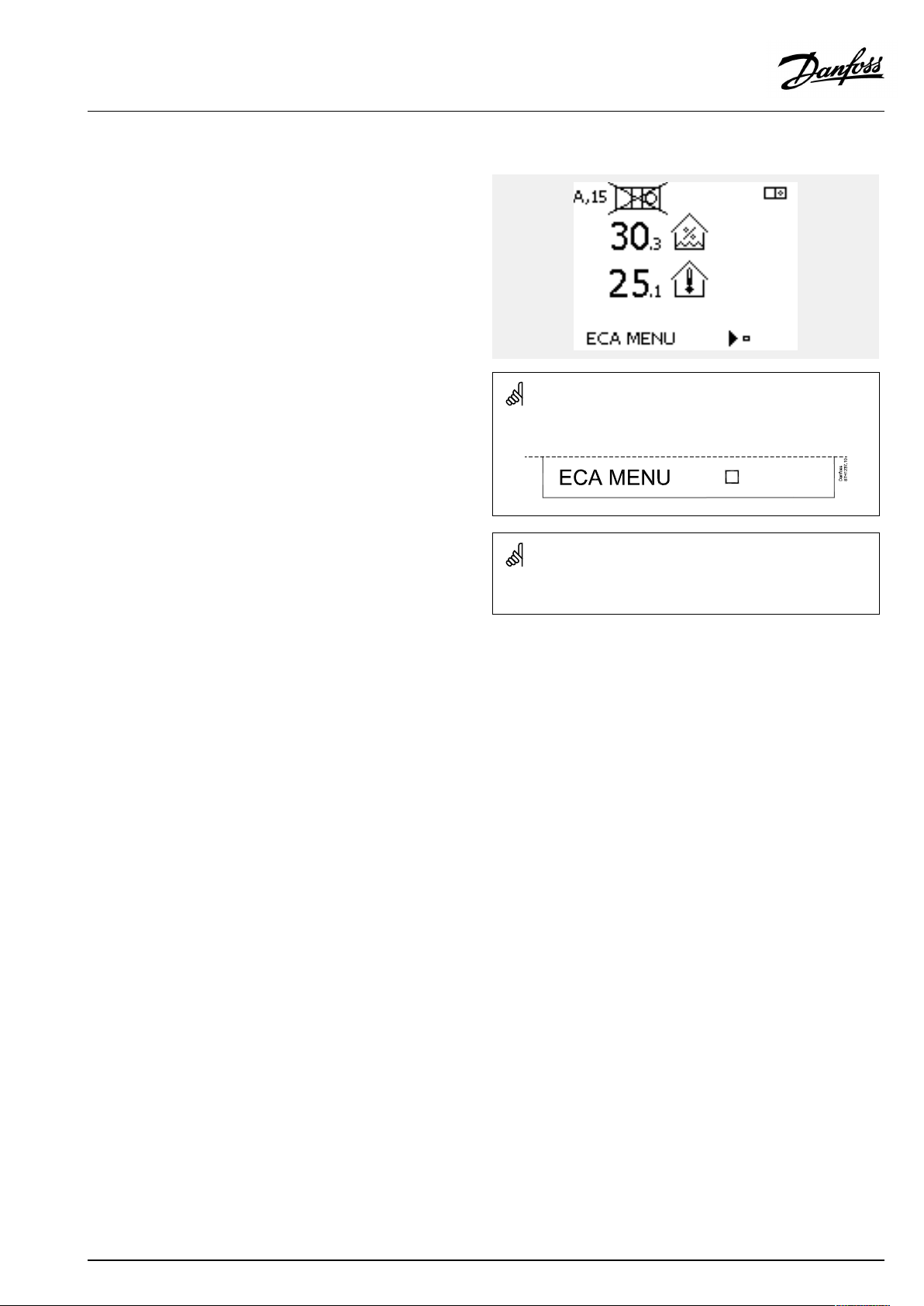
2.3.6Situation:ECAMENUpointonly
Thisdisplayindicatesthatanapplicationhasnotbeenuploadedor
thecommunicationtotheconnectedECLcontrollerisnotworking
properly.
AnXontheECLcontrollersymbolindicatesthatthereisno
communicationwithamasterontheECL485busnetwork.
Helpprocedure:
1.CheckwiringconnectionsbetweenECA30/31andECL
Comfortcontroller
2.Checkcommunicationaddress:
InECLComfort:MENU>Commoncontrollersettings>System
>Communication>ECL485addr.:
Asstandard"15"isselected.
InECA30/31:ECAMENU>ECASystem>ECACommunication
>Connectionaddr.:
Asstandard"15"isselected.
DisplaypartofECA30/31:
InasystemwithECA30/31andECLComfortcontroller(s)oneofthe
ECLComfortcontrollersmustbemaster(address15).
AQ089886456757en-010401
©Danfoss|2021.05|7
Page 8
ECA30/31forECLComfort210/210B/296/310/310B
2.3.7Situation:ECApicture-Dateandroomtemperature
IntheECApicturethedateisshown.Someapplicationsshowthe
roomtemperaturetoo.
Modeselectoranddesiredroomtemperaturearenotshown.
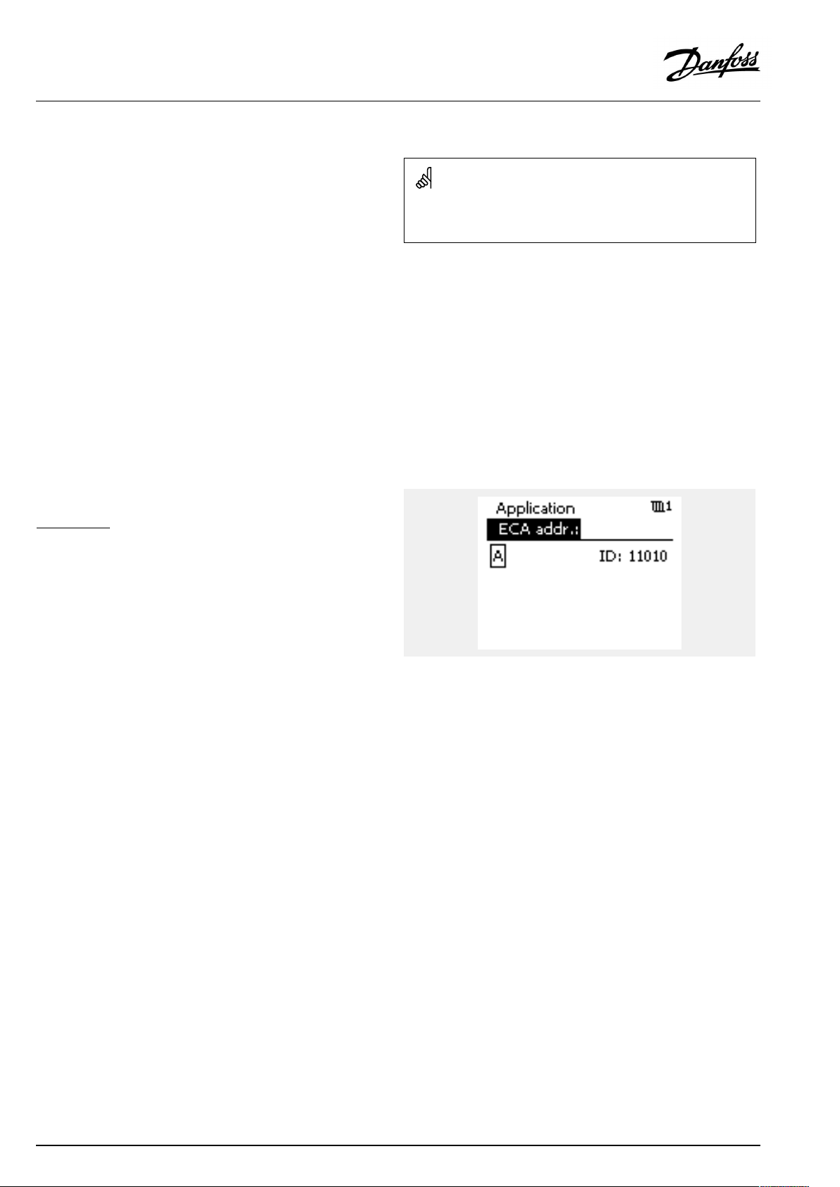
2.3.8Override
TheECA30/31isnotfactorysetuptocommunicatewithaheating
circuitintheconnectedECLcontroller.
Inordertoarrangetemporarilyoverride,theECA30/31mustbe
setuptocommunicatewiththedesiredheatingcircuitintheECL
Comfortcontroller.
Seethefollowingexamplesforestablishingthedesired
communication.
Example:
TheECA30/31isnotsetuptocommunicatewithaheatingcircuit
intheconnectedECLcontroller.
Seetheexampleforestablishingthedesiredcommunication.
ECLComfort:
Circuit1>MENU>Settings>Application:
ECAaddr.:SettoA
8|©Danfoss|2021.05
AQ089886456757en-010401
Page 9
ECA30/31forECLComfort210/210B/296/310/310B
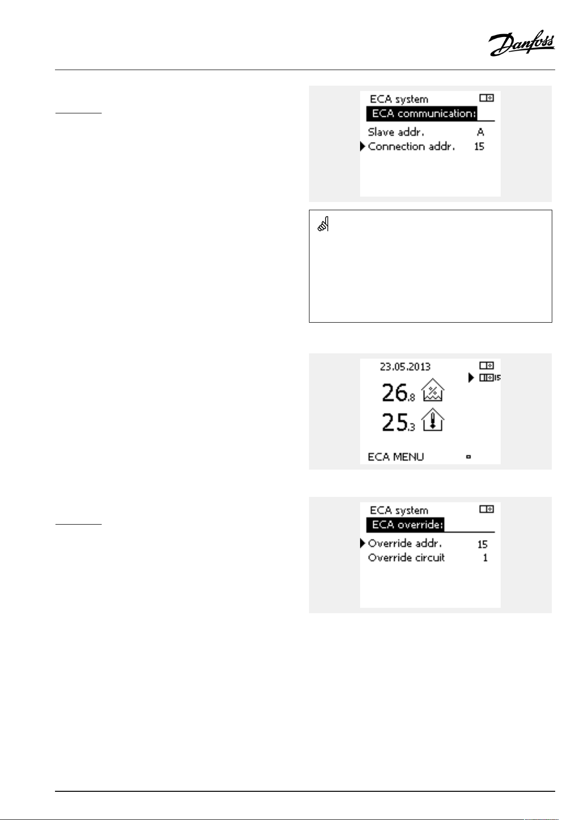
Example,continued:
ECA30/31:
ECAMENU>ECASystem>ECAcommunication:
Connectionaddr.:
•Setto15(onlyonecontroller,themaster,inthesystem)
•Setto1...9or15(whenmasterandslave(s)controllersinthe
system)
Alternativesettingofaddress:
1.ChooseECApicture
2.Movethepositionindicatortothecontrollericon
3.Pushthedialtoselectthecontrollericon
4.Turnthedialtoselectdesiredaddress
5.Pushthedialtoconfirmyourchoice
ExampleshowingconnectedECLComfortControlleraddress.
Example,continued:
ECA30/31:
ECAMENU>ECASystem>ECAoverride:
Overrideaddr.:
•Setto15(onlyonecontroller,themaster,inthesystem)
•Setto1...9or15(whenmasterandslave(s)controllersinthe
system)
Overridecircuit:
•Setthedesiredcircuitnumber(1-4).
Note:
•Onlyheatingcircuitscanbeoverridden.
•IntheECLComfortcontrollertheheatingcircuitinquestion
mustbesettoAorB.
AQ089886456757en-010401
©Danfoss|2021.05|9
Page 10
ECA30/31forECLComfort210/210B/296/310/310B
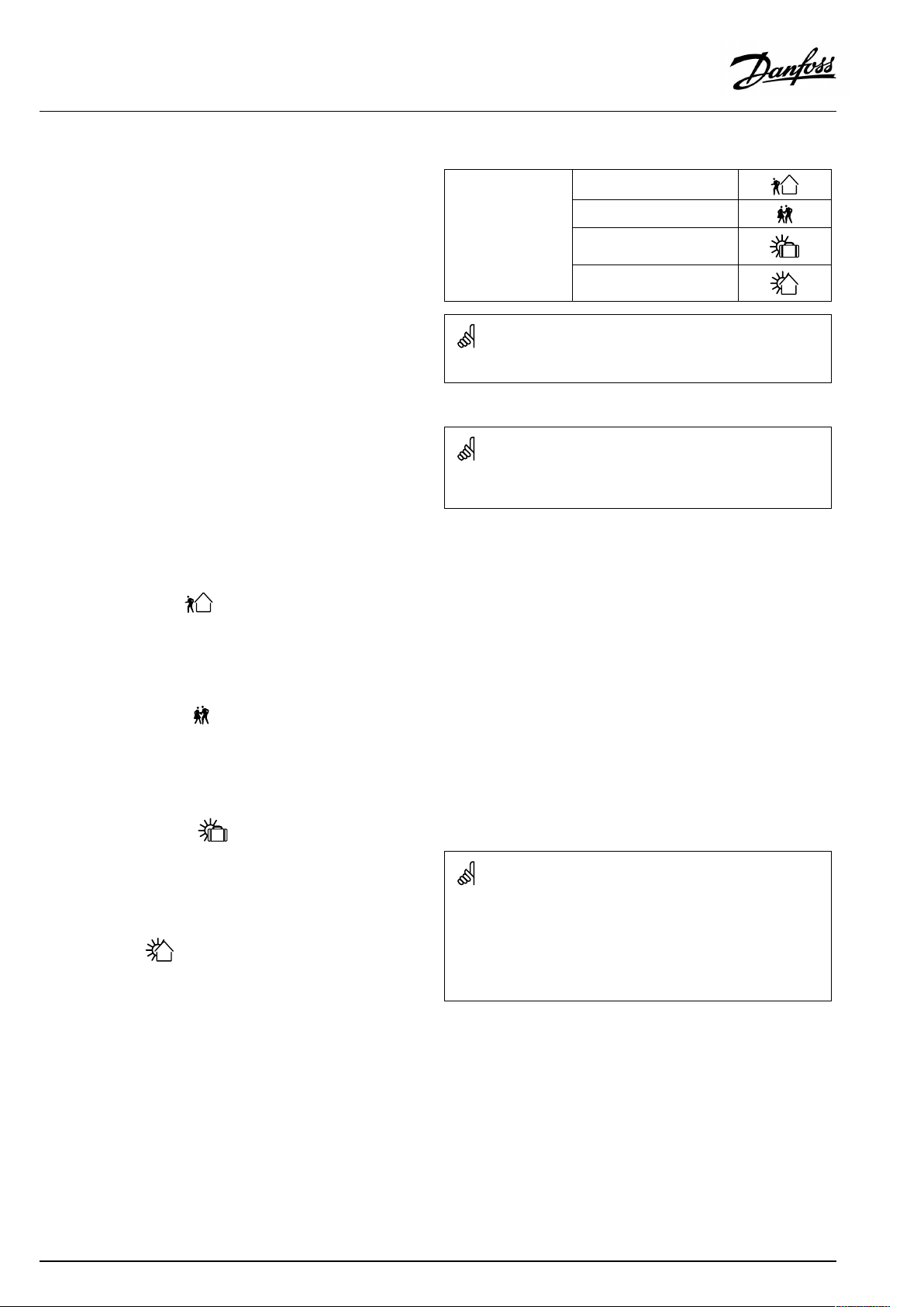
2.4OverridefunctionsECA30/31
Thetabletotherightshowstheoverridefunctions.
Theoverridefunctionsareenabledwhencommunicationhasbeen
established(seeECAMENU>ECAsystem>ECAoverride).
Furthermore,thefunctionselectoroftheheatingcircuitmustbein
scheduledmode.
Ifholidaymodeisactivatedthenholidaymodetakespriorityand
cancelstheoverridemode.
Exampleonoverride:
•GotoECAMENU
•Placecursoratclocksymbol(Functionselector)
•Push/turndialtoselectoverrideform
Extendedsavingmode:
Extendedsavingmode:
Extendedcomfortmode:
Overridefunctions:
Holidayawayfromhome:
Holidayathome:
DHWcircuitscannotbetemporarilyoverridden.
Ifscheduledmodeisnotselected,thecursorcannotbeplacedatthe
functionselector.
Whenselected,theoverridestoptimecanbeset(max.23hours
ahead).
Inaddition,thedesiredroomtemperatureintheoverrideperiod
canbeset.
Extendedcomfortmode
:
Whenselected,theoverridestoptimecanbeset(max.23hours
ahead).
Inaddition,thedesiredroomtemperatureintheoverrideperiod
canbeset.
Holidayawayfromhome
:
Whenselected,theoverridestopdatecanbeset(max.365days
ahead).
Inaddition,thedesiredroomtemperatureintheoverrideperiod
canbeset.
Holidayathome
:
Whenselected,theoverridestopdatecanbeset(max.365days
ahead).
Inaddition,thedesiredroomtemperatureintheoverrideperiod
canbeset.
When“holiday”overrideisselected,thestopdateisthelastholiday
date.
Example:
Stopdateissetto"15.11"(15thofNovember),meaningthatfrom
midnightbetweenthe15thofNovemberandthe16thofNovember,
theoverrideisdisabled.
10|©Danfoss|2021.05
AQ089886456757en-010401
Page 11

ECA30/31forECLComfort210/210B/296/310/310B
3.0Installation
3.1Importantsafetyandproductinformation
3.1.1Importantsafetyandproductinformation
ThisInstallationGuideisassociatedwiththeRemoteControlUnits
ECA30(codeno.087H3200)andECA31(codeno.087H3201).
ECA30isaremotecontrolunitwithroomtemperaturesensor.
ECA31isaremotecontrolunitwithroomtemperaturesensorand
relativehumiditysensor.
ECA30andECA31canbeusedwithECLComfort210/210B,ECL
Comfort296andECLComfort310/310Bcontrollers.
Forinformationongeneralfunctionspleaseconsulttheinstallation
guidefortheapplicationkeyinquestion.
AdditionaldocumentationforECLComfort210and310,modules
andaccessoriesisavailableonwww.ecl.doc.danfoss.com.
SafetyNote
Toavoidinjuryofpersonsanddamagestothedevice,itisabsolutely
necessarytoreadandobservetheseinstructionscarefully.
Necessaryassembly,start-up,andmaintenanceworkmustbe
performedbyqualifiedandauthorizedpersonnelonly.
Locallegislationsmustberespected.Thiscomprisesalsocable
dimensionsandtypeofisolation(doubleisolatedat230V).
AfusefortheECLComfortinstallationismax.10Atypically.
TheambienttemperaturerangesforECLComfortinoperationare:
ECLComfort210/310:0-55°C
ECLComfort296:0-45°C.
Exceedingthetemperaturerangecanresultinmalfunctions.
Installationmustbeavoidedifthereisariskforcondensation(dew).
Thewarningsignisusedtoemphasizespecialconditionsthatshould
betakenintoconsideration.
Thissymbolindicatesthatthisparticularpieceofinformationshould
bereadwithspecialattention.
AsthisOperatingGuidecoversseveralsystemtypes,specialsystem
settingswillbemarkedwithasystemtype.Allsystemtypesareshown
inthechapter:'Identifyingyoursystemtype'.
AQ089886456757en-010401
©Danfoss|2021.05|11
Page 12

ECA30/31forECLComfort210/210B/296/310/310B
°C(degreesCelsius)isameasuredtemperaturevaluewhereasK
(Kelvin)oftenisusedfortemperaturedifferences.
TheIDno.isuniquefortheselectedparameter.
ExampleFirstdigitSeconddigitLastthreedigits
1117411174
-
Circuit1Parameterno.
12174
IfanIDdescriptionismentionedmorethanonce,itmeansthatthere
arespecialsettingsforoneormoresystemtypes.Itwillbemarked
withthesystemtypeinquestion(e.g.12174-A266.9).
ParametersindicatedwithanIDno.like"1x607"meanauniversal
parameter.
xstandsforcircuit/parametergroup.
1
-
DisposalNote
Thissymbolontheproductindicatesthatitmaynot
bedisposedofashouseholdwaste.
Itmustbehandedovertotheapplicabletake-back
schemefortherecyclingofelectricalandelectronic
equipment.
•Disposeoftheproductthroughchannelsprovided
forthispurpose.
•Complywithalllocalandcurrentlyapplicablelaws
andregulations.
2
Circuit2Parameterno.
174
12|©Danfoss|2021.05
AQ089886456757en-010401
Page 13

ECA30/31forECLComfort210/210B/296/310/310B
3.1.2UpdateofECA30/31software
ThefirmwareoftheECA30/31canbeautomaticallyupdated
whenakeycontainingnewECA30/31firmwareisinsertedin
theECLComfortcontrollerandthecontrollerhasnotyetgotan
applicationinstalled.
BoththeECLComfortcontrollerandtheECA30/31musthave
softwareversion1.39orhigher.
TheECA30/31firmwareupdatecanalsobestartedmanuallyby
usingtheupdatefirmwaremenuintheECA30/31duringnormal
operation.
ThenewfirmwaremustbecopiedtotheECA30/31unitbefore
itcanbeapplied.
Duringthecopyprocessananimationshowingtheprogresswill
beshown.
WhenthenewfirmwarehasbeencopiedtotheECA30/31the
copyprocesswillendwiththispicture.
AfterthenewfirmwarehasbeencopiedtotheECA30/31unit
itwillupdatethedeviceitselfwhileshowinganhour-glassand
aprogressbar.
AQ089886456757en-010401
©Danfoss|2021.05|13
Page 14

ECA30/31forECLComfort210/210B/296/310/310B
Duringupdate:
•DonotremovetheKEY
Ifthekeyisremovedbeforethehour-glassisshown,youhave
tostartafresh.
•Donotdisconnectthepower
Ifthepowerisinterruptedwhenthehour-glassisshown,the
controllerwillnotwork.
14|©Danfoss|2021.05
AQ089886456757en-010401
Page 15

ECA30/31forECLComfort210/210B/296/310/310B
3.2Mounting
3.2.1MountingtheRemoteControlUnitsECA30/31
Selectoneofthefollowingmethods:
•Mountingonawall,ECA30/31
•Mountinginapanel,ECA30
Screwsandrawlplugsarenotsupplied.
Mountingonawall
MountthebasepartoftheECA30/31onawallwithasmooth
surface.Establishtheelectricalconnections.PlacetheECA30/
31inthebasepart.
Mountinginapanel
MounttheECA30inapanelusingtheECA30framekit(ordercode
no.087H3236).Establishtheelectricalconnections.Securethe
framewiththeclamp.PlacetheECA30inthebasepart.TheECA
30canbeconnectedtoanexternalroomtemperaturesensor.
TheECA31mustnotbemountedinapanelifthehumidity
functionistobeused.
AQ089886456757en-010401
©Danfoss|2021.05|15
Page 16

ECA30/31forECLComfort210/210B/296/310/310B
3.3Placingthetemperaturesensors
Roomtemperaturesensor
(ESM-10,ECA30/31RemoteControlUnit)
Placetheroomsensorintheroomwherethetemperatureistobe
controlled.Donotplaceitonoutsidewallsorclosetoradiators,
windowsordoors.
16|©Danfoss|2021.05
AQ089886456757en-010401
Page 17

ECA30/31forECLComfort210/210B/296/310/310B
3.4Electricalconnections
AQ089886456757en-010401
©Danfoss|2021.05|17
Page 18

ECA30/31forECLComfort210/210B/296/310/310B
3.4.1Electricalconnections,ECA30/31
Terminal
ECL
Terminal
ECA30/31
30
31
4
1
322
333
4
5
*
Afteranexternalroomtemperaturesensorhasbeenconnected,
Description
Twistedpair
Twistedpair
Ext.roomtemperature
sensor*
Type
(recomm.)
Cable2x
twistedpair
ESM-10
ECA30/31mustberepowered.
ThecommunicationtotheECA30/31mustbesetupintheECL
Comfortcontrollerin'ECAaddr. '
TheECA30/31mustbesetupaccordingly.
AfterapplicationsetuptheECA30/31isreadyafter2–5min.A
progressbarintheECA30/31isdisplayed.
18|©Danfoss|2021.05
Iftheactualapplicationcontainstwoheatingcircuits,itispossible
toconnectanECA30/31toeachcircuit.Theelectricalconnections
aredoneinparallel.
Max.2ECA30/31canbeconnectedtoanECLComfort310controller
ortoECLComfort210/296/310controllersinamaster-slavesystem.
ECAinformationmessage:
‘Applicationreq.newerECA’:
Thesoftware(firmware)ofyourECAdoesnotcomplywiththe
software(firmware)ofyourECLComfortcontroller .Pleasecontact
yourDanfosssalesoffice.
AQ089886456757en-010401
Page 19

ECA30/31forECLComfort210/210B/296/310/310B
Someapplicationsdonotcontainfunctionsrelatedtoactualroom
temperature.TheconnectedECA30/31willonlyfunctionasremote
control.
Totalcablelength:Max.200m(allsensorsincl.internalECL485
communicationbus).
Cablelengthsofmorethan200mmaycausenoisesensibility(EMC).
AQ089886456757en-010401
©Danfoss|2021.05|19
Page 20

ECA30/31forECLComfort210/210B/296/310/310B
3.5ECA30/31setupprocedures
ECA30(codeno.087H3200)isaremotecontrolunitwithbuilt-in
roomtemperaturesensor.
ECA31(codeno.087H3201)isaremotecontrolunitwithbuilt-in
roomtemperaturesensorandhumiditysensor(relativehumidity).
Anexternalroomtemperaturesensorcanbeconnectedtoboth
typestosubstitutethebuilt-insensor.
AnexternalroomtemperaturesensorwillberecognizedatECA
30/31power-up.
Connections:Seethesection'Electricalconnections' .
Max.twoECA30/31canbeconnectedtooneECLcontroller
orasystem(master-slave)consistingofseveralECLcontrollers
connectedonthesameECL485bus.Inthemaster-slavesystem
onlyoneoftheECLcontrollersismaster.TheECA30/31can,
amongothers,besetto:
•monitorandsettheECLcontrollerremotely
•measuretheroomtemperatureand(ECA31)humidity
•extendcomfort/savingperiodtemporarily
AfterapplicationuploadintheECLComfortcontroller,theremote
controlunitECA30/31willafterapprox.oneminuteaskto'Copy
application'.
ConfirmthisinordertouploadtheapplicationtotheECA30/31.
Menustructure
ThemenustructureofECA30/31isan"ECAMENU"andtheECL
menu,copiedfromtheECLComfortcontroller.
TheECAMENUcontains:
•ECAsettings
•ECAsystem
•ECAfactory
ECAsettings:Offsetadjustmentofthemeasuredroom
temperature.
Offsetadjustmentofrelativehumidity(ECA31only).
ECAsystem:Display,communication,overridesettingsandversion
info.
ECAfactory:EraseofallapplicationsintheECA30/31,restoreto
factorysettings,resetofECLaddressandfirmwareupdate.
PartoftheECA30/31displayinECLmode:
PartoftheECA30/31displayinECAmode:
Ifonlythe"ECAMENU"isshown,itcanindicatethattheECA30/31is
nothavingcorrectcommunicationaddress.
SeeECAMENU>ECAsystem>ECAcommunication:ECLaddress.
InmostcasestheECLaddresssettingmustbe"15" .
20|©Danfoss|2021.05
RegardingECAsettings:
WhenECA30/31isnotusedasremoteunit,theoffsetadjustments
menu(s)arenotpresent.
AQ089886456757en-010401
Page 21

ECA30/31forECLComfort210/210B/296/310/310B
TheECLmenusareasdescribedfortheECLcontroller.
MostofthesettingsdonedirectlyintheECLcontrollercanbedone
viatheECA30/31too.
Allsettingscanbeseeneveniftheapplicationkeyisnotinsertedin
theECLcontroller.
Forchangingsettings,theapplicationkeymustbeinserted.
TheKeyoverview(MENU>'Commoncontrollersettings'>'Key
functions')doesnotshowtheapplicationsofthekey.
TheECA30/31willdisplaythisinformation(anXontheECA30/31
symbol)iftheapplicationintheECLcontrollerdoesnotcomplywith
theECA30/31:
Intheexample1.10iscurrentversionand1.42isdesiredversion.
DisplaypartofECA30/31:
Thisdisplayindicatesthatanapplicationhasnotbeenuploadedorthe
communicationtotheECLcontroller(master)isnotworkingproperly.
AnXontheECLcontrollersymbolindicateswrongsetupof
communicationaddresses.
DisplaypartofECA30/31:
NewerversionsofECA30/31indicatetheaddressnumberofthe
connectedECLComfortcontroller.
AddressnumbercanbechangedintheECAMENU.
Astand-aloneECLControllerhastheaddress15.
AQ089886456757en-010401
©Danfoss|2021.05|21
Page 22

ECA30/31forECLComfort210/210B/296/310/310B
WhenECA30/31isinECAMENUmode,thedateandmeasured
roomtemperatureisdisplayed.
ECAMENU>ECAsettings>ECAsensor
RoomTOffset
Settingrange
Factorysetting
–10.0...10.0K0.0K
Themeasuredroomtemperaturecanbecorrected
withanumberofKelvin.Thecorrectedvalueisused
bytheheatingcircuitintheECLcontroller.
Minus
value:
0.0K:
Plus
Theindicatedroomtemperatureislower.
Nocorrectionofthemeasuredroomtemperature.
Theindicatedroomtemperatureishigher.
value:
ECAMENU>ECAsettings>ECAsensor
RHoffset(ECA31only)
Settingrange
Factorysetting
–10.0...10.0%0.0%
Themeasuredrelativehumiditycanbecorrected
withanumberof%-values.Thecorrectedvalueis
usedbytheapplicationintheECLcontroller.
Minus
value:
Theindicatedrelativehumidityislower.
Example:
RoomToffset:
Displayedroomtemperature:
RoomToffset:
Displayedroomtemperature:
Example:
RHoffset:
Displayedrelativehumidity:
RHoffset:
Displayedrelativehumidity:
0.0K
21.9°C
1.5K
23.4°C
0.0%
43.4%
3.5%
46.9%
0.0%:
Plus
Nocorrectionofthemeasuredrelativehumidity.
Theindicatedrelativehumidityishigher.
value:
ECAMENU>ECAsystem>ECAdisplay
Backlight(displaybrightness)
Settingrange
Factorysetting
0...10
Adjustthebrightnessofthedisplay.
0:
10:
Weakbacklight.
Strongbacklight.
5
22|©Danfoss|2021.05
AQ089886456757en-010401
Page 23

ECA30/31forECLComfort210/210B/296/310/310B
ECAMENU>ECAsystem>ECAdisplay
Contrast(displaycontrast)
Settingrange
0...103
Adjustthecontrastofthedisplay.
Factorysetting
0:
10:
Lowcontrast.
Highcontrast.
ECAMENU>ECAsystem>ECAdisplay
Useasremote
Settingrange
Factorysetting
OFF/ON*)
ECA30/31canactasasimpleornormalremote
controlfortheECLcontroller.
OFF:
ON:
*):
Simpleremotecontrol,noroomtemperaturesignal.
Remotecontrol,roomtemperaturesignalisavailable.
Differently,dependingonchosenapplication.
ECAMENU>ECAsystem>ECAcommunication
Slaveaddr.(Slaveaddress)
Settingrange
Factorysetting
A/B
Thesettingof'Slaveaddr.'isrelatedtothesetting
'ECAaddress'intheECLcontroller.
IntheECLcontrolleritisselectedfromwhichECA30
/31unittheroomtemperaturesignalisreceived.
WhensettoOFF:TheECAmenushowsdateandtime.
WhensettoON:TheECAmenushowsdateandroomtemperature
A
ForinstallationofanapplicationinanECLComfort210/296/310
controllerthe'Slaveaddr. 'mustbeA.
(andforECA31relativehumidity).
A:
B:
AQ089886456757en-010401
TheECA30/31hastheaddressA.
TheECA30/31hastheaddressB.
IftwoECA30/31areconnectedinthesameECL485bussystem,the
'Slaveaddr. 'mustbe"A"intheoneECA30/31unitand"B"intheother.
©Danfoss|2021.05|23
Page 24

ECA30/31forECLComfort210/210B/296/310/310B
ECAMENU>ECAsystem>ECAcommunication
Connectionaddr.(Connectionaddress)
Settingrange
1…9/15
SettingoftheaddresstowhichECLcontrollerthe
communicationmustrun.
Factorysetting
15
AnECA30/31caninanECL485bussystem(master–slave)besetto
communicate,onebyone,withalladdressedECLcontrollers.
1..9:
15:
Slavecontrollers.
Mastercontroller .
ECAMENU>ECAsystem>ECAoverride
Overrideaddr.(Overrideaddress)
Settingrange
Factorysetting
OFF/1…9/15OFF
Thefeature'Override'(toextendedcomfortor
savingperiodorholiday)mustbeaddressedtothe
ECLcontrollerinquestion.
OFF:
Overridenotpossible.
Example:
Connectionaddr.=15:TheECA30/31communicateswiththe
Connectionaddr.=2:TheECA30/31communicateswiththe
Theremustbeamastercontrollerpresentinordertobroadcasttime
anddateinformation.
AnECLComfortcontroller210/310,typeB(withoutdisplayanddial)
cannotbeassignedtotheaddress0(zero).
Overridefunctions:
ECLmastercontroller.
ECLcontrollerwithaddress2.
Extendedsavingmode:
Extendedcomfortmode:
Holidayawayfromhome:
1..9:
15:
24|©Danfoss|2021.05
Addressofslavecontrollerforoverride.
Addressofmastercontrollerforoverride.
Holidayathome:
OverridebymeansofsettingsinECA30/31arecancellediftheECL
Comfortcontrollergoesintoholidaymodeorischangedtoanother
modethanscheduledmode.
ThecircuitinquestionforoverrideintheECLcontrollermustbein
scheduledmode.
Seealsotheparameter'Overridecircuit' .
AQ089886456757en-010401
Page 25

ECA30/31forECLComfort210/210B/296/310/310B
ECAMENU>ECAsystem>ECAoverride
Overridecircuit
Settingrange
OFF/1…4OFF
Thefeature'Override'(toextendedcomfortor
savingperiodorholiday)mustbeaddressedtothe
heatingcircuitinquestion.
Factorysetting
ThecircuitinquestionforoverrideintheECLcontrollermustbein
scheduledmode.
Seealsotheparameter'Overrideaddr. ' .
OFF:
1…4:
Noheatingcircuitisselectedforoverride.
Theheatingcircuitnumberinquestion.
Example1:
(OneECLcontrollerandoneECA30/31)
Overrideofheating
circuit2:
Example2:
(SeveralECLcontrollersandoneECA30/31)
Overrideofheating
circuit1inECL
controllerwiththe
address6:
Quickguide"ECA30/31tooverridemode":
1.GotoECAMENU
2.Movecursorto"Clock"symbol
3.Selectthe"Clock"symbol
4.Chooseandselectoneof4overridefunctions
5.Belowtheoverridesymbol:Sethoursordate
6.Belowhours/date:Setdesiredroomtemperaturefortheoverride
period
Set'Connectionaddr. 'to15Set'Override
Set'Connectionaddr .'to6Set'Override
circuit'to2
circuit'to1
ECAMENU>ECAsystem>ECAversion
ECAversion(read-outonly),examples
Codeno.
Hardware
Software
Buildno.
Serialno.
Productionweek
087H3200
A
1.42
5927
13579
23.2012
TheECAversioninformationisusefulinservicesituations.
AQ089886456757en-010401
ECA30/31:
Connectionaddress(master:15,slaves:1-9)
15
©Danfoss|2021.05|25
Page 26

ECA30/31forECLComfort210/210B/296/310/310B
ECAMENU>ECAfactory>ECAclearapps.
Eraseallapps.(Eraseallapplications)
EraseallapplicationswhichareintheECA30/31.
Aftererasing,theapplicationcanbeuploadedagain.
NO:
YES:
ECAMENU>ECAfactory>ECAdefault
Restorefactory
TheECA30/31issetbacktofactorysettings.
Affectedsettingsbytherestoreprocedure:
•RoomToffset
•RHoffset(ECA31)
•Backlight
•Contrast
•Useasremote
•Slaveaddr.
•Connectionaddr.
•Overrideaddr.
•Overridecircuit
•Overridemode
•Overridemodeendtime
Theeraseprocedureisnotdone.
Theeraseprocedureisdone(await5sec.).
Aftertheeraseprocedure,apop-upinthedisplayindicates"Copy
application".Choose"Yes".
HereaftertheapplicationisuploadedfromtheECLcontroller.An
uploadbarisshown.
NO:
YES:
Therestoreprocedureisnotdone.
Therestoreprocedureisdone.
26|©Danfoss|2021.05
AQ089886456757en-010401
Page 27

ECA30/31forECLComfort210/210B/296/310/310B
ECAMENU>ECAfactory>ResetECLaddr.
ResetECLaddr.(ResetECLaddress)
IfnoneoftheconnectedECLComfortcontrollershastheaddress15,
theECA30/31cansetallconnectedECLcontrollersontheECL485
busbacktoaddress15.
NO:
Theresetprocedureisnotdone.
TheECL485busrelatedaddressoftheECLcontrollerisfound:
MENU>'Commoncontrollersettings'>'System'>'Communication'>
'ECL485addr. '
YES:
Theresetprocedureisdone(await10sec.).
ECAMENU>ECAfactory>Updatefirmware
Updatefirmware
TheECA30/31canbeupdatedwithnewfirmware(software)..
ThefirmwarecomeswiththeECLapplicationkey,whenthekey
versionisatleast2.xx.
Ifnonewfirmwareisavailable,asymboloftheapplicationkey
isdisplayedwithanX.
NO:
YES:
Theupdatingprocedureisnotdone.
Theupdatingprocedureisdone.
The"ResetECLaddr. "cannotbeactivatedifoneormoreofthe
connectedECLComfortcontrollershastheaddress15.
InasystemwithMASTER/SLAVEcontrollers,onlyoneMASTER
controllerwithaddress15isallowed.
IfbymistakemoreMASTERcontrollersarepresentinanECL485
communicationbussystem,decidewhichcontrolleristobeMASTER.
Changetheaddressintheremainingcontrollers.However,thesystem
willoperatebutnotbestablewithmorethanoneMASTERcontroller.
TheECA30/31automaticallyverifiesifanewfirmwareispresenton
theapplicationkeyintheECLComfortcontroller.
TheECA30/31isautomaticallyupdatedatnewapplicationuploadin
theECLComfortcontroller.
TheECA30/31isnotautomaticallyupdatedwhenconnectedtoan
ECLComfortcontrollerwithuploadedapplication.Amanualupdate
isalwayspossible.
AQ089886456757en-010401
©Danfoss|2021.05|27
Page 28

ECA30/31forECLComfort210/210B/296/310/310B
4.0Settings
4.1Roomtemperature
Settingthedesiredroomtemperature,ECA30/ECA31
Thedesiredroomtemperaturecanbesetexactlyasinthe
controller.However,othersymbolscanbepresentinthedisplay
(pleasesee'Whatdothesymbolsmean?').
WiththeECA30/ECA31youcanoverridethedesiredroom
temperaturesetinthecontrollertemporarilybymeansoftheoverride
functions:
28|©Danfoss|2021.05
AQ089886456757en-010401
Page 29

ECA30/31forECLComfort210/210B/296/310/310B
4.2Optimization
MENU>Settings>Optimization
Boost
CircuitSettingrange
OFF/1...99%OFF
Shortenstheheating-upperiodbyincreasingthedesiredflowtemperature
bythepercentageyouset.
OFF:
1-99%:
Theboostfunctionisnotactive.
Thedesiredflowtemperatureisincreasedtemporarily
Factorysetting
withthesetpercentage.
Inordertoshortentheheating-upperiodafterasaving
temperatureperiod,thedesiredflowtemperaturecanbeincreased
temporarily(max.1hour).Atoptimizingtheboostisactiveinthe
optimizationperiod('Optimizer').
IfaroomtemperaturesensororanECA30/31isconnected,the
booststopswhentheroomtemperatureisreached.
11012
AQ089886456757en-010401
©Danfoss|2021.05|29
Page 30

ECA30/31forECLComfort210/210B/296/310/310B
4.3Holiday
TheECA30/31cannotoverridetheholidayscheduleofthe
controllertemporarily.
However,itispossibletomakeuseofthefollowingoptionsfrom
theECA30/31whenthecontrollerisinscheduledmode:
Dayoff
Holiday
Relaxing(extendedcomfortperiod)
Goingout(extendedsavingperiod)
Energy-savingtrick:
Use'Goingout'(theextendedsavingperiod)forairingpurposes(e.g.
forventilatingtheroomsbymeansoffreshairfromopenwindows).
Quickguide"ECA30/31tooverridemode":
1.GotoECAMENU
2.Movecursorto"Clock"symbol
3.Selectthe"Clock"symbol
4.Chooseandselectoneof4overridefunctions
5.Belowtheoverridesymbol:Sethoursordate
6.Belowhours/date:Setdesiredroomtemperaturefortheoverride
period
30|©Danfoss|2021.05
AQ089886456757en-010401
Page 31

ECA30/31forECLComfort210/210B/296/310/310B
Installer:
By:
Date:
AQ089886456757en-010401
©Danfoss|2021.05|31
Page 32

ECA30/31forECLComfort210/210B/296/310/310B
32|©Danfoss|2021.05
*087H9176*
AQ089886456757en-010401
 Loading...