

Page 1

Installation Instructions
Top Fan Replacement for E3h/E4h Drives
Description
The top fan assembly in E3h and E4h drives consists of 2 fans
within a single fan housing. The top fan replacement kit
contains all parts required to replace 1 fan in the top fan
assembly.
Part number Kit description
176F3176 Top fan for IP20 enclosure
Table 1.1 Part Number for the Top Fan Kit
Items Supplied
The door fan replacement kit contains the following:
1 fan
•
Installation instructions
•
Safety Instructions
Only qualied, Danfoss authorized personnel are allowed to
install the parts described in these installation instructions.
Disassembly and reassembly of the drive must be done in
accordance with the corresponding service manual.
WARNING
DISCHARGE TIME
The drive contains DC-link capacitors, which can remain
charged even when the drive is not powered. High voltage
can be present even when the warning LED indicator lights
are
Failure to wait 40 minutes after power has been
o.
removed before performing service or repair work can result
in death or serious injury.
Stop the motor.
•
Disconnect AC mains and remote DC-link power
•
supplies, including battery back-ups, UPS, and DClink connections to other drives.
Disconnect or lock PM motor.
•
Wait 40 minutes for capacitors to discharge fully.
•
Before performing any service or repair work, use
•
an appropriate voltage measuring device to make
sure that the capacitors are fully discharged.
WARNING
ELECTRICAL SHOCK HAZARD
VLT® series drives contain dangerous voltages when
connected to mains voltage. Improper installation, and
installing or servicing with power connected, can cause
death, serious injury, or equipment failure.
To avoid death, serious injury, or equipment failure:
Only use
•
Disconnect the drive from all power sources before
•
installation or service.
Treat the drive as live whenever the mains voltage
•
is connected.
Follow the guidelines in these instructions and local
•
electrical safety codes.
qualied
electricians for the installation.
Danfoss A/S © 06/2017 All rights reserved. MI35N102
Page 2
Installation Instructions Top Fan Replacement for E3h/E4h Drives
Installation Instructions
Removing the Top Fan
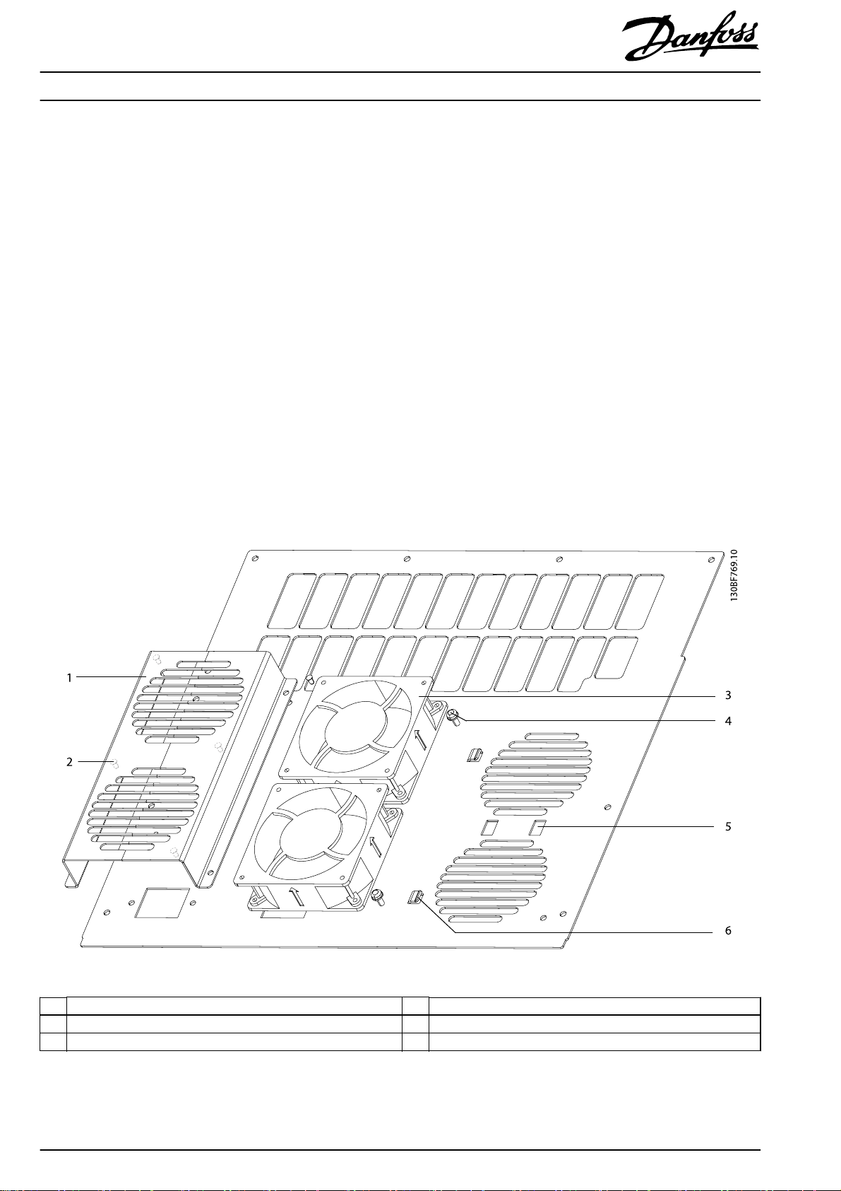
To remove and replace the top fan, use the following procedures. Refer to Illustration 1.1.
1. Remove 2 screws (T25) from the fan housing.
2. Slide the fan housing and fans out from under the retaining clips.
3. Unplug the in-line connector attaching the fan cable.
4. Feed the cable through the cable access hole.
5. Lift the fans from the pins in the fan housing.
Installing the Top Fan
1. Place the fans over the pins in the fan housing. Check that the air direction arrows point upward and away from the drive.
2. Feed the fan cables through the cable access hole on the top plate.
3. Reconnect the in-line cable connector.
4. Slide the fan housing and fans into position under the retaining clips.
5. Secure 2 screws (T25) in the fan housing.
1Fan housing 4Screw (T25)
2 Mounting pin (inside housing) 5 Cable access hole
3 Fan 6 Retaining clip
Illustration 1.1 Top Fan
2
Danfoss A/S © 06/2017 All rights reserved. MI35N102
Page 3

Installation Instructions Top Fan Replacement for E3h/E4h Drives
MI35N102 Danfoss A/S © 06/2017 All rights reserved.
3
Page 4

Danfoss can accept no responsibility for possible errors in catalogues, brochures and other printed material. Danfoss reserves the right to alter its products without notice. This also applies to products already on
order provided that such alterations can be made without subsequential changes being necessary in specifications already agreed. All trademarks in this mate rial are property of the respective companies. Danfoss
and the Danfoss logotype are trademarks of Danfoss A/S. All rights reserved.
Danfoss A/S
Ulsnaes 1
DK-6300 Graasten
vlt-drives.danfoss.com
MI35N102130R0767 06/2017
*MI35N102*
 Loading...