

Page 1
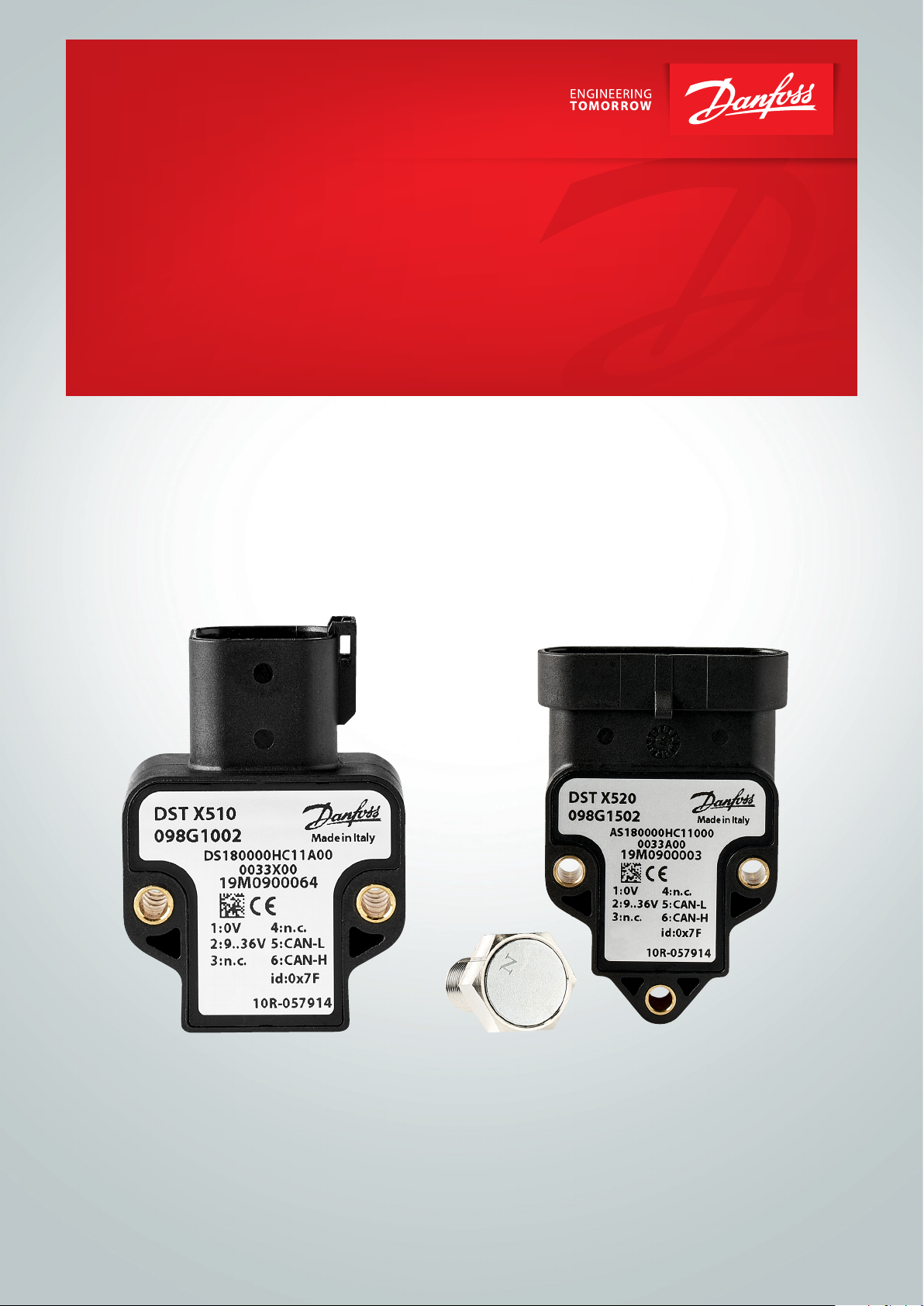
Operation guide
Rotary position sensors
SAE J1939 Digital output
DST X510 and DST X520
ia.danfoss.com
Page 2

Operation guide | DST X510 and DST X520 Rotary position sensors SAE J1939
Table of contents
Contents
1. General information................................................................................................................................... 2
1.1 Contact........................................................................................................................................................... 2
1.2 General............................................................................................................................................................ 2
2. Abbreviations and terms.......................................................................................................................... 3
3. Reference documents.............................................................................................................................. 3
4. Electrical connections and Block diagram ........................................................................................ 4
4.1 Deutsch version with shaft.................................................................................................................... 4
4.2 AMP version with shaft............................................................................................................................ 5
4.3 AMP version without shaft................................................................................................................... . 6
4.4 Cable without shaft................................................................................................................................. . 7
4.5 Danfoss Hall-eect rotary sensor: Block diagram......................................................................... 8
5. Default SAE J1939 denitions................. ........................................................................................ 8
6. Getting started............................................................................................................................................ 9
7. How to change the name........................................................................................................................ 12
8. How to change the transmission rate................................................................................................. 13
9. How to change the source address................................................................................................. .... 14
1. General Information
1.1 Contact
Danfoss A/S
Industrial Automation
DK-6430 Nordborg
Denmark
www.ia.danfoss.com
E-mail: [email protected]
1.2 General
This document represents a Danfoss SAE J1939
denition for HALL-eect single turn rotary
sensors.
2 | © Danfoss | DCS (im) | 2019.10
AQ304226795410en-0001010 | IC.PS.P21.I2.02
Page 3
Operation guide | DST X510 and DST X520 Rotary position sensor SAE J1939
2. Abbreviations and
terms
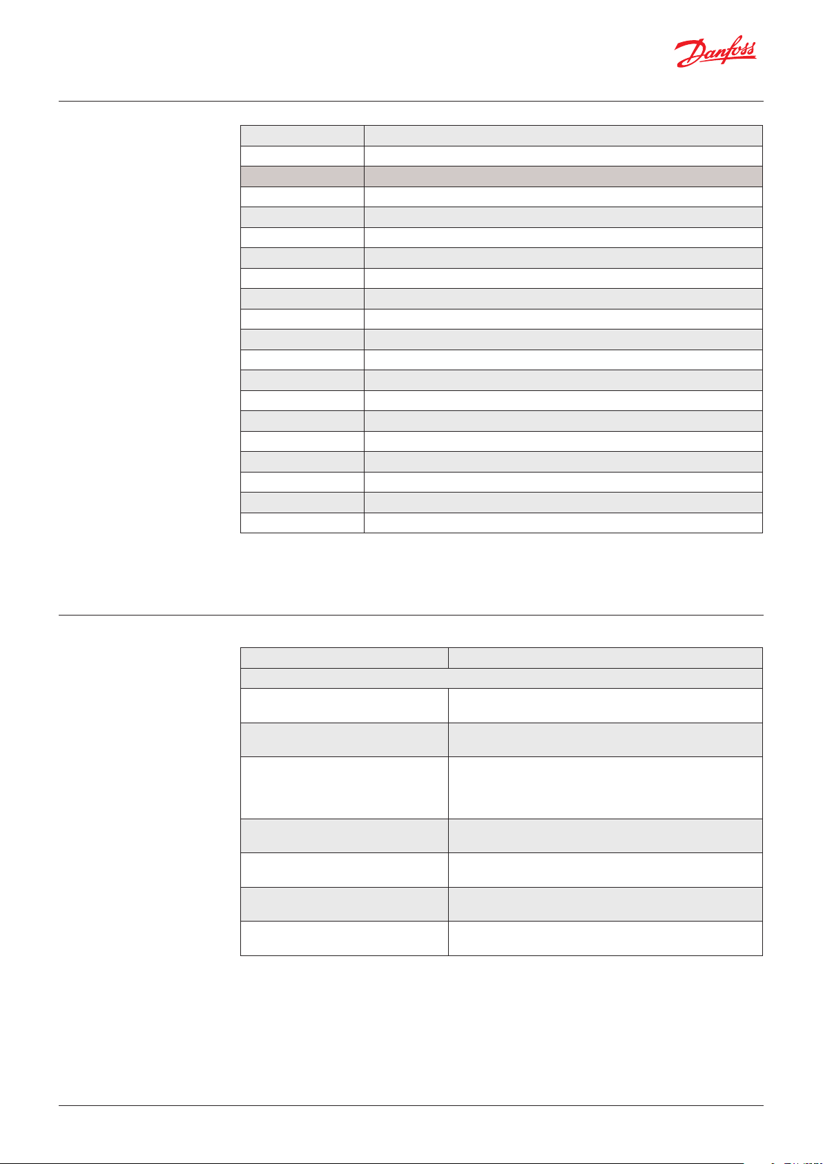
Abbreviation / Term Denition
SAE Society of Automotive Engineers
ECU Electronic Control Unit
CA Controller Application
PDU Protocol Data Unit
NMT Network Management
PGN Parameter Group Number
AC Address Claiming
MSB Most Signicant Byte
LSB Least Signicant Byte
SOF Start Of Frame
RTR Remote Transmission Request
CRC Cyclic Redundancy Check
ACK Acknowledgement
EOF End Of Frame
SRR Substitute Remote Request
IDE Identier Extension
POST Power On Self Test
CW Clockwise
CWW Counterclockwise
3. Reference documents
Document Contents
J1939 - Recommended Practice for a Serial Control & Communications Vehicle Network
J1939/11 - Physical layer - 250k bits/s,
Shield Twisted Pair
J1939/13 - O-Board Diagnostic
Connector
J1939/21 - Dat Link Layer CAN frame (29-bit identier, PGN etc.), transport protocol
J1939/31 - Network Layer Services and functions needed for intercommunication
J1939/71 - Vehicle Application Layer Standard parameters which are frouped together in a
J1939/73 - Application Layer Diagnostics
J1939/81 - Network Management Information about the content of an ECU Name and how
Bus physical properties
Standard connector for diagnostic purpose
functions, and 5 types of message types: Commands,
Requests, Broadcasts/Reponses, Acknowledgement, and
Group Functions
between dierent segments of a J1939 network
message frrame and given a PGN
Functions and messages for accessing diagnostic and
calibration data
the ECU claims an addressing using that Name
© Danfoss | DCS (im) | 2019.10
AQ304226795410en-0001010 | IC.PS.P21.I2.02 | 3
Page 4
Operation guide | DST X510 and DST X520 Rotary position sensors SAE J1939
4. Electrical Connections
and Block diagram
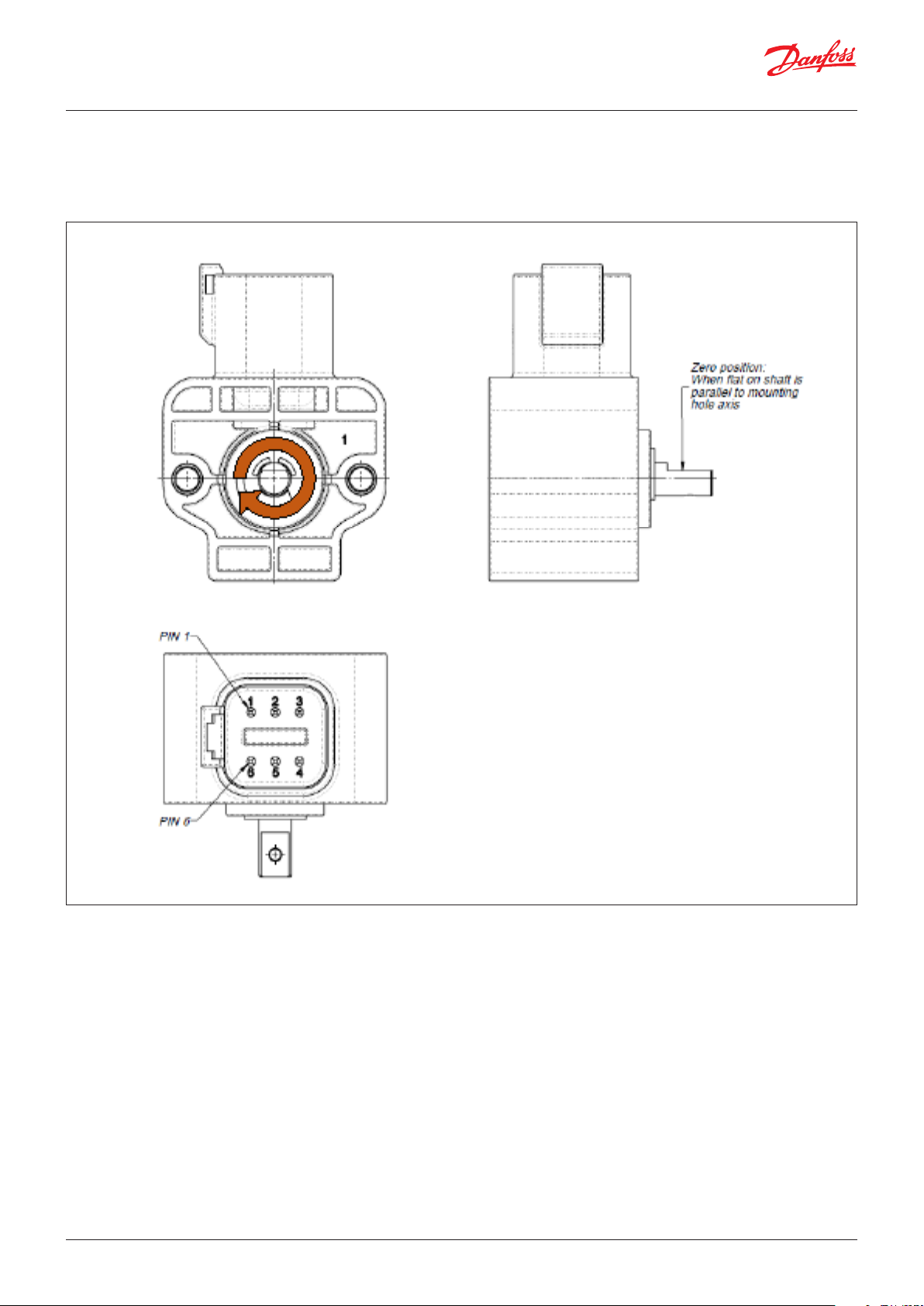
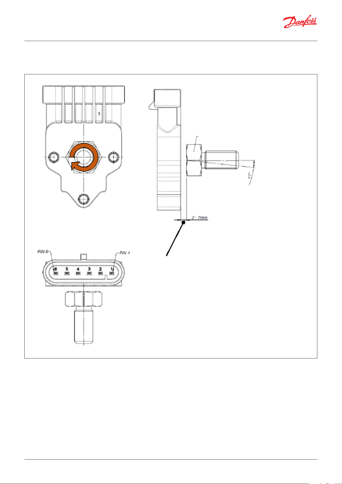
4.1 Deutsch version with shaft
CONNECTIONS
1.: OV (GND)
2.: + VS (+9 - +36 VDC)
3.: NC
4.: NC
5.: CAN-L
6.: CAN-H
4 | © Danfoss | DCS (im) | 2019.10
AQ304226795410en-0001010 | IC.PS.P21.I2.02
Page 5
Operation guide | DST X510 and DST X520 Rotary position sensor SAE J1939
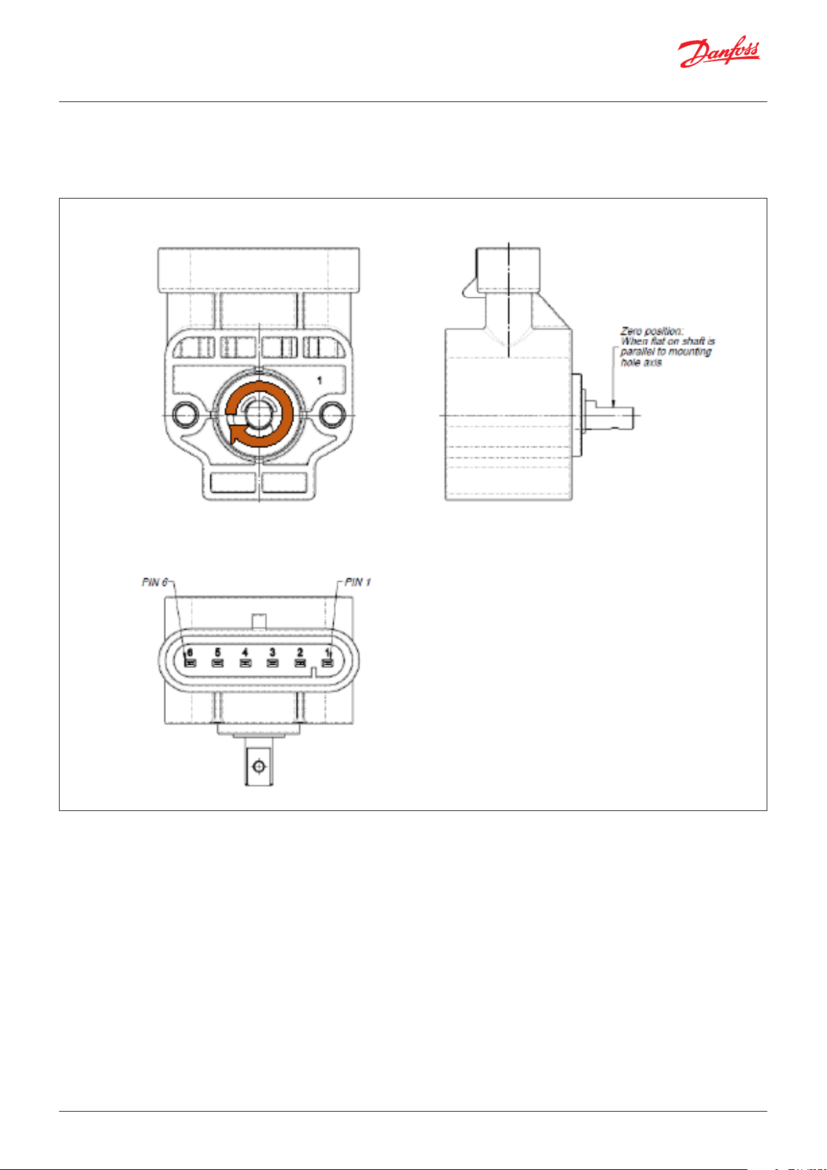
4.2 AMP version with shaft
CONNECTIONS
1.: OV (GND)
2.: + VS (+9 - +36 VDC)
3.: NC
4.: NC
5.: CAN-L
6.: CAN-H
© Danfoss | DCS (im) | 2019.10
AQ304226795410en-0001010 | IC.PS.P21.I2.02 | 5
Page 6
Operation guide | DST X510 and DST X520 Rotary position sensors SAE J1939
4.3 AMP version without shaft
M10 CH17 Magnet
< Suggested less than 1°
Air gab
CONNECTIONS
1.: OV (GND)
2.: + VS (+9 - +36 VDC)
3.: NC
4.: NC
5.: CAN-L
6.: CAN-H
6 | © Danfoss | DCS (im) | 2019.10
AQ304226795410en-0001010 | IC.PS.P21.I2.02
Page 7
Operation guide | DST X510 and DST X520 Rotary position sensor SAE J1939
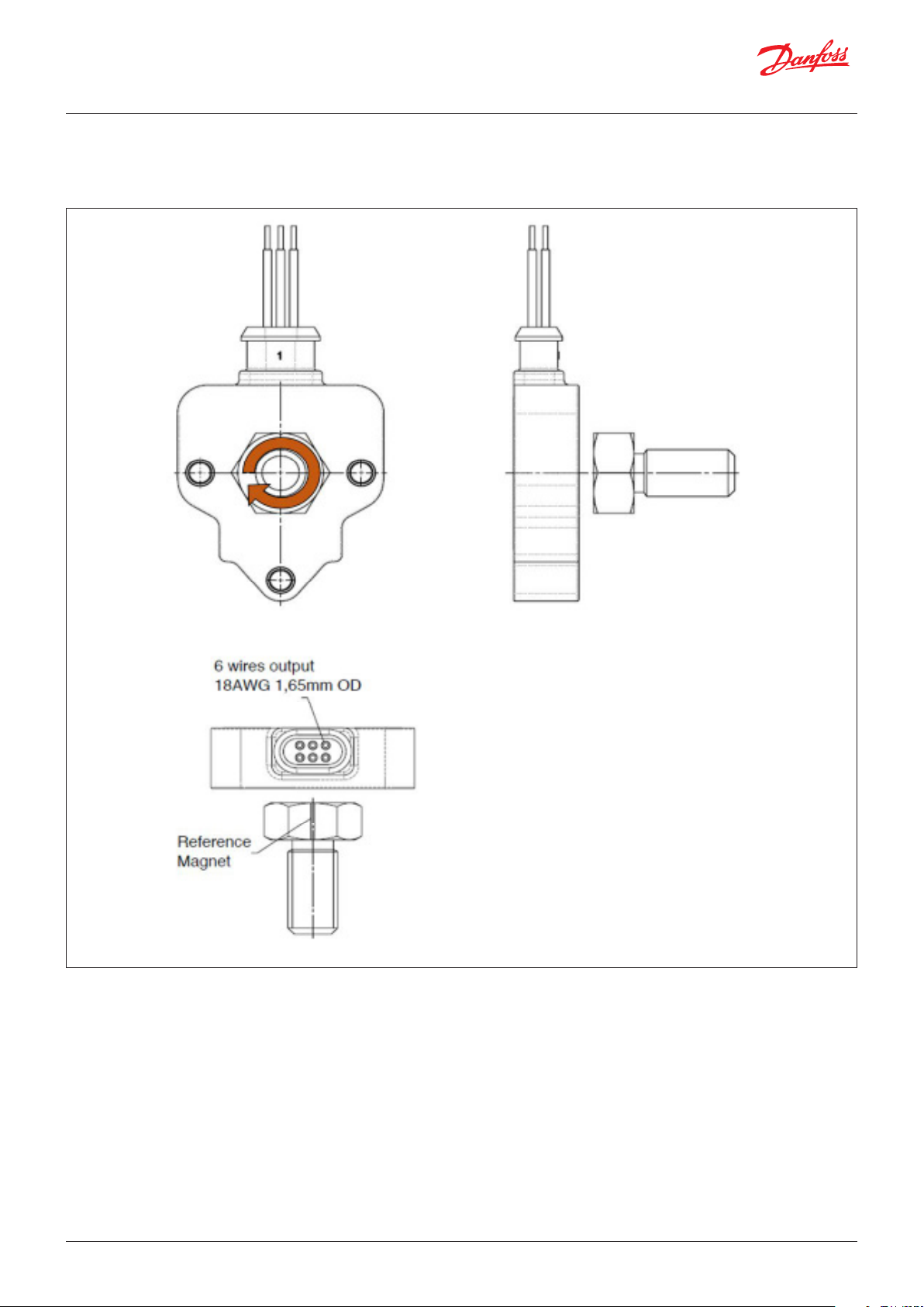
4.4 Cable without shaft
CONNECTIONS
Black: GROUND
Red: + SUPPLY 1
Yellow: NC
Green: NC
Blue: CAN-L
White: CAN-H
NOTE:
Make sure that the CANbus is terminated. The
inpedance measured between CAN-H and
CAN-L mus be 60 Ω that means the cable must
b e connected to a 120 Ω resistor on each
end of the bus line. Internally the transducer
is not terminated with resistor of 120 Ω. Do
not confuse the signal lines of the CANbus,
otherwise communication with the transducer
is impossible.
© Danfoss | DCS (im) | 2019.10
AQ304226795410en-0001010 | IC.PS.P21.I2.02 | 7
Page 8
Operation guide | DST X510 and DST X520 Rotary position sensors SAE J1939
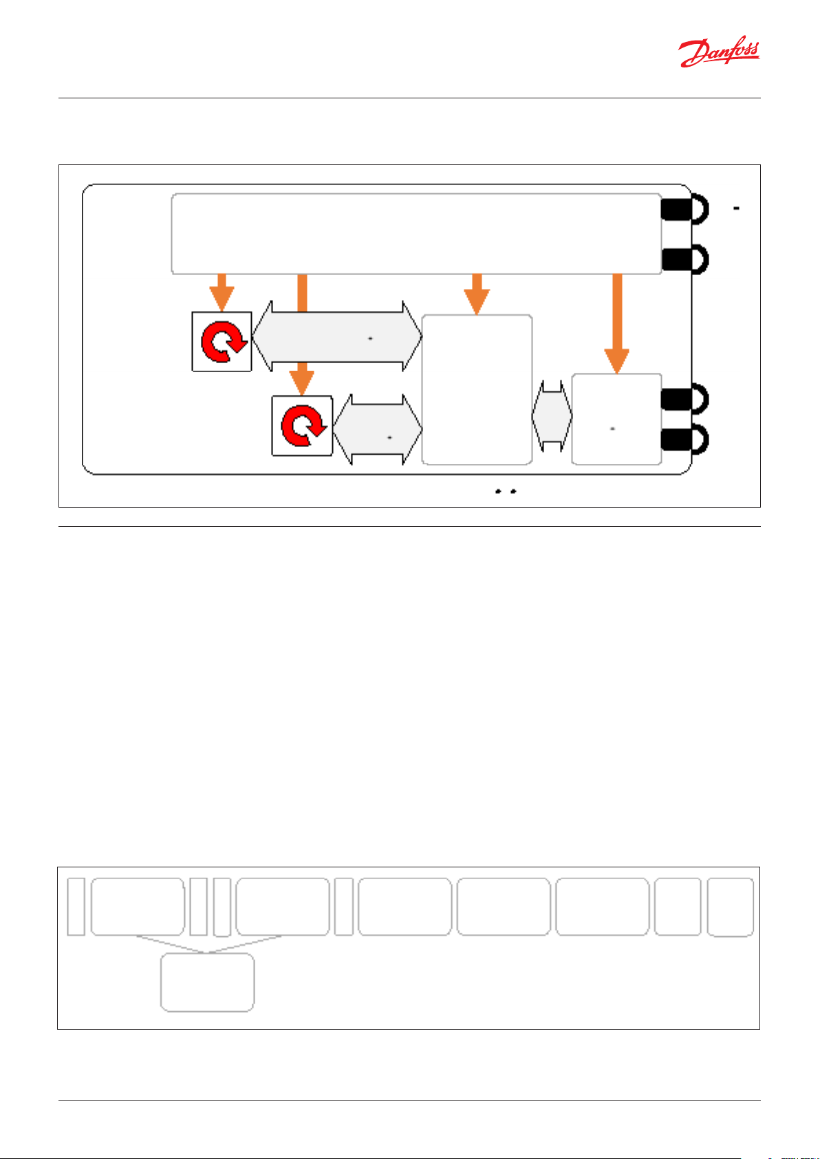
4.5 Danfoss Hall-eect rotary sensor: Block diagram
Power Management
+ Vs
GND
Angle 1 (CW)
Hall- CHIP 1
Angle 2(CCW)
Hall- CHIP 2
5. Default SAE J1939
denitions
Data & Diagnostic
Main
Controller
Data &
CAN
Transceiver
Diagnostic
• Data rate: 250 kbps
• Arbitrary Address Capable: 1
• Transmission rate: 100 ms
• Identier: 18FF0B15h
• PGN: 65291 (OFF0Bh) - “Proprietary B”
• Source Address: 21(15h)
• Priority: 6
• Data:
- Byte 0, 1: Angle 1 position unsigned int. 16 bit: 0 - 3599 (CW/CCW according to the ordering code,
Angle position 0 - 359.9°; 0.1° resolution)
- Byte 2, 3: Angle 2 position 0 - 3599 (CW/CCW according to the ordering code, Angle position 0 -
359.9°, 0.1° resolution)
- Byte 4, 5, 6: 0xFF - Not in use
- Byte 7: Error code
• Diagnostic message: DM 13 only supported
CAN-H
CAN-L
S
11-bit
O
CAN ID
F
8 | © Danfoss | DCS (im) | 2019.10
S
R
R
29-bit
Identier
The current data rate of Danfoss Hall-eect
single-turn rotary sensors with SAE J1939 output
is 250 kbps. A typical message containing 8 data
bytes is 128 bits long (excluding bits used for bit
stung) which in time is approximately 500 µs.
I
18-bit
D
CAN ID
E
R
T
R
6-bit
Control Field
0-8 byte
Data Field
16-bit
CRC Field
Fig. 1 SAE J1939/21 Message Format
AQ304226795410en-0001010 | IC.PS.P21.I2.02
2- bit
ACK
7- bit
EOF
Page 9
Operation guide | DST X510 and DST X520 Rotary position sensor SAE J1939
3 bits 1 bit 1 bit 8 bits 8 bits 8 bits
-
6. Getting started
Priority
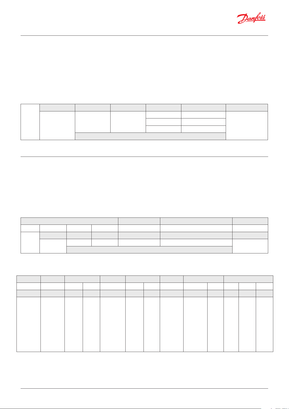
J1939 uses 29-bit identier dened within CAN
2.0B protocol shown in table 1.4
The device is congured as Arbitrary Address
Capable device, thus it can claim other
addresses, sending the Address Claimed
message with the source address in the range
128 to 247 inclusive
PDU format PDU specic
Reserved Data page
1.
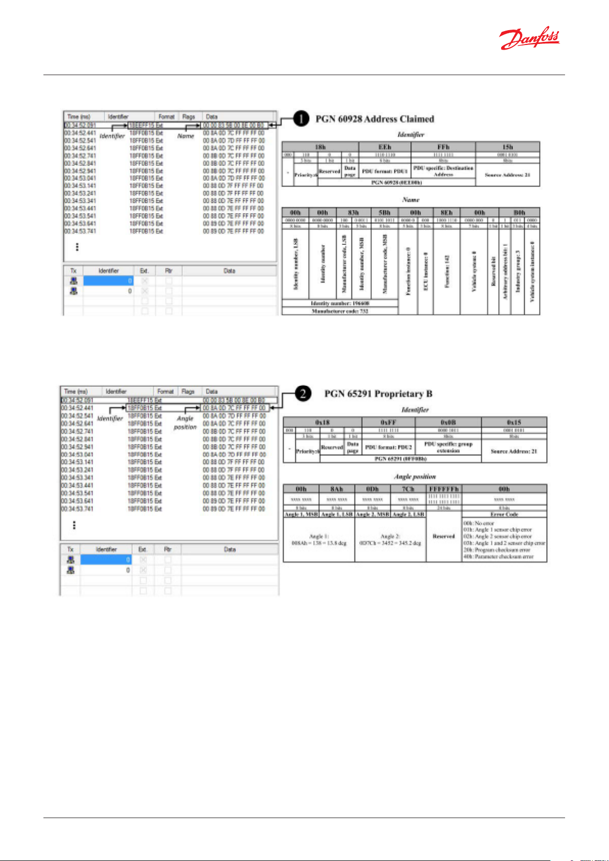
When the sensor is turned on, it sends an
Address Claimed message according to PGN
60928 as shown in the example of Fig. 2
(page 10). The message is composed of:
- Identier: 18EEFFXXh (Tabel 2)
- Data Field: device Name (Tabel 3)
< 240: PDU1 Destination Address
≥ 240: PDU2 Group extension
PGN
If no other Address Claimed message with
the dame Source Address is received, or if the
arbitration is won, the device uses that address
and begins regular network communications with
that address. If no address in the range of 128
to 247 is available (arbitration always lost), the
device sends the Cannot Claim Address message
using the NULL address (254). In this case, regular
network communications are suspended.
Source Address
Table1: Structure of 29 bit identier
After the sensor has acquired a valid
2.
address, it starts sending the angle position
message according to PGN 65291 as shown
in the example of Fig. 3 (page 10). The
message is composed of:
- Identier: 0x18FF0BXXh (Tabel 4)
- Data Field: Angle position (Tabel 5)
In case of an error occurs, the angle position message will be sent with Angle 1 and Angle 2 MSB = 0xFF
and LSB = 0XFF.
18h EEh FFh XXh
000 110 0 0 1110 1110 1111 1111 0001 0101
3 bits 1 bit 1 bit 8 bits 8 bits 8 bits
-
Priority: 6
XXh XXh XXh 5Bh XXh XXh XXh XXh
xxxx xxxx xxxx xxxx 100 x xxxx 0101 1011 x xxxx xxx xxxx xxxx xxxx xxxx 0 x xxx xxxx
8 bits 8 bits 3 bits 5 bits 8bits 5 bits 3 bits 8 bits 7 bits 1 bit 1 bit 3 bits 4 bits
LSB
Identity number,
Reserved Data page PDU format: PDU1 PDU specic: Destination Address
PGN 60928 (0EE00h)
Table 2: PNG 60928 Address Claimed: Identier denition
Identity number
LSB
Manufacturer code,
MSB
Identity number,
MSB
Manufacturer code,
Function instance
ECU instance
Function
Vehicle system
Reserved bit
Source Address
Industry group
Arbitrary address bit
instance
Vehicle system
© Danfoss | DCS (im) | 2019.10
Table 3: PNG 60928 Address Claimed: Name denition
AQ304226795410en-0001010 | IC.PS.P21.I2.02 | 9
Page 10
Operation guide | DST X510 and DST X520 Rotary position sensors SAE J1939
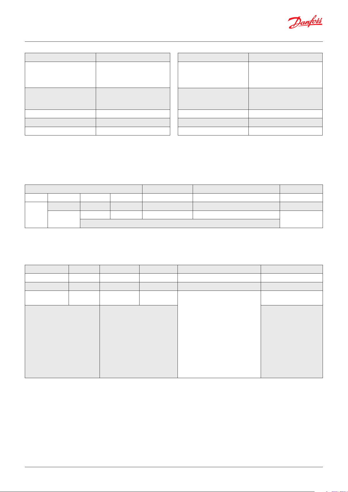
Field Description
0: Single Address Capable
Arbitrary address bit
Industry group
Vehicle system instance 0
Vehicle system 0
Reserved bit 0
18h FFh 0Bh XXh
000 110 0 0 1111 1111 0000 1011 0001 0101
3 bits 1 bit 1 bit 8 bits 8 bits 8 bits
-
Priority: 6
device (not implemented)
1: Arbitrary Address Capable
device
2: Agricultural and Forestry
Equipment
3: Construction Equipment
Table 4: Danfoss J1939 Name denition for HaLL-eect single turn rotary sensors
Reserved Data page PDU format: PDU2 PDU specic: Group extension
PGN 65291 (0FF0Bh)
Field Description
Function 142 (8Eh): Rotary Sensor
Function instance 0
ECU instance 0
Manufacturer code 732 (2D Ch): Danfoss A/S
Identity number Programmed by: Danfoss A/S
Source Address
Table 5: PGN 65291 Proprietary B: Identier denition
XXh XXh XXh XXh FFFFFFh XXh
xxxx xxxx xxxx xxxx xxxx xxxx xxxx xxxx 1111 11111 1111 1111 11111 1111 xxxx xxxx
8 bits 8 bits 8 bits 8 bits 24 bits 8 bits
Angle 1,
MSB
Data type: 16-bit unsigned
integer
Resolution: 0.1 deg
Ex.: 008Ah = 138 = 13.8 deg
Angle 1,
LSB
Angle 2,
MSB
Data type: 16-bit unsigned
integer
Resolution: 0.1 deg
Ex.: 0D7Ch = 3452 = 345.2 deg
Angle 2,
LSB
Error Code
0000 0000 No error
0000 0001 Angle 1
sensor chip error
0000 0010 Angle 2
Reserved
Table 6: PGN 65291 Proprietary B: Angle position denition
sensor chip error
0000 0100 Magnetic
eld too high/low
0010 0000 Program
checksum error
0100 0000 Parameter
checksum error
10 | © Danfoss | DCS (im) | 2019.10
AQ304226795410en-0001010 | IC.PS.P21.I2.02
Page 11
Operation guide | DST X510 and DST X520 Rotary position sensor SAE J1939
Fig. 2: Example: Address Claimed message
© Danfoss | DCS (im) | 2019.10
Fig. 3: Example: Angle position message
AQ304226795410en-0001010 | IC.PS.P21.I2.02 | 11
Page 12
Operation guide | DST X510 and DST X520 Rotary position sensors SAE J1939
7. How to change the
name
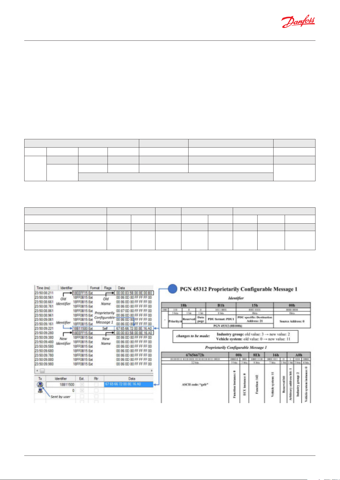
The Name of the sensor can be congured by
sending Destination Specic - Proprietarily
Congurable Message 1 according to PNG 45312
as shown in the example in Fig.4 (page 12).
The message is composed of:
• Identier: 18BXXXXh (table 7)
• Note: Consider that the Destianation
Address is the address of the sensor, while
the Source Address refers to the address
of the user CAN controller that sends the
message.
• Data eld: Proprietarily Congurabe
Message 1 (table 8)
18h B1h XXh XXh
000 110 0 0 1011 0001 xxxx xxxx xxxx xxxx
3 bits 1 bit 1 bit 8 bits 8 bits 8 bits
-
Priority: 6
Reserved Data page PDU format: PDU1 PDU specic: Destination Address
PGN 45312 (0B100h)
Source Address
Table 7: PGN 45312 Proprietarily Congurable Message 1: Identier denition
67656672h XXh XXh XXh XXh
0110 0111 0110 0101 0110 0110 0111 0010
32 bits 5 bits 3 bits 8 bits 7 bits 1 bit 1 bit 3 bits 4 bits
ASCII code: “gefr”
xxxx x xxx xxxx xxxx xxxx xxx 0 x xxx xxxx
Function
instance
ECU
instance
Function
Vehicle
system
Reserved
bit
Arbitrary
address
bit
Industry
group
Table 8: PGN 45312 Proprietarily Congurable Message 1: Messager denition
Vehicle
system
instance
12 | © Danfoss | DCS (im) | 2019.10
Fig. 4: Example: How to change the name
AQ304226795410en-0001010 | IC.PS.P21.I2.02
Page 13
Operation guide | DST X510 and DST X520 Rotary position sensor SAE J1939
8. How to change the
transmission rate
18h B1h XXh XXh
000 110 0 0 1011 0010 xxxx xxxx xxxx xxxx
3 bits 1 bit 1 bit 8 bits 8 bits 8 bits
-
Priority: 6
67656672h XXh XXh 0000h
0110 0111 0110 0101 0110 0110 0111
0010
32 bits 8 bits 8 bits 16 bits
ASCII code: “gefr”
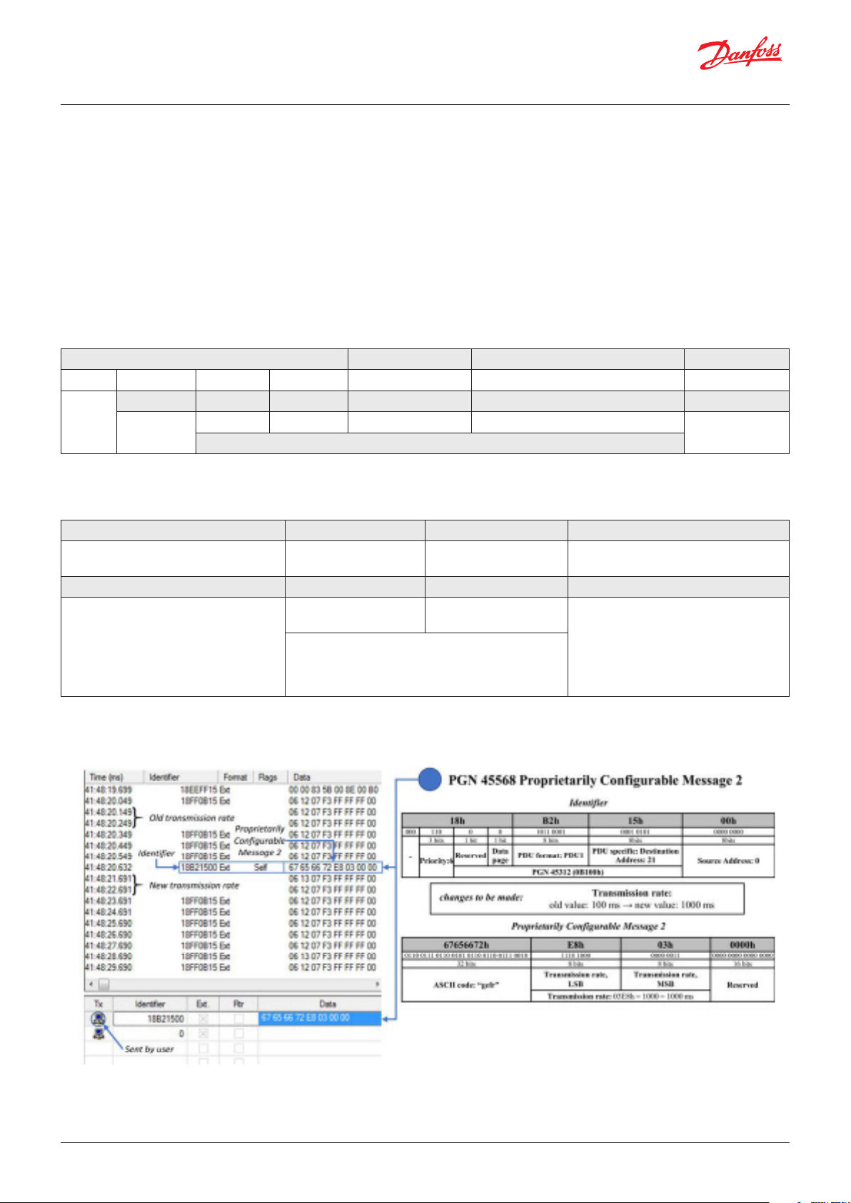
The Transmission Rate of the sensor can be
congured by sending the Destination Specic Proprietarily Congurable Message 2 according
to PGN 45568 as shown in the example Fig. 5
(page 13).
The message is composed of:
• Identier: 18B2XXXXh (table 9)
• Note: Consider that the Destianation
Address is the address of the sensor, while
the Source Address refers to the address
of the user CAN controller that sends the
message.
• Data eld: Proprietarily Congurabe
Message 2 (table 10)
Reserved Data page PDU format: PDU1 PDU specic: Destination Address
PGN 45568 (0B200h)
Table 9: PGN 45568 Proprietarily Congurable Message 2: Identier denition
xxxx xxxx xxxx xxxx 0000 0000 0000 0000
Transmission rate
LSB
Data type: 16-bit unsigned integer
Resolution: 1 ms
Range: 10 - 65535; 0= stop transmission
Ex.: 0032h = 50 = 50 ms
Transmission rate
MSB
Reserved
Source Address
Table10: PGN 45568 Proprietarily Congurable Message 2: Message denition
Fig. 5: Example: How to change the transmission rate
© Danfoss | DCS (im) | 2019.10
AQ304226795410en-0001010 | IC.PS.P21.I2.02 | 13
Page 14
Operation guide | DST X510 and DST X520 Rotary position sensors SAE J1939
9. How to change the
source address
The Source Address of the sensor can be
congured by sending the Command Address
Message according to PGN 65240 (FED8h). Since
The messages must be sent:
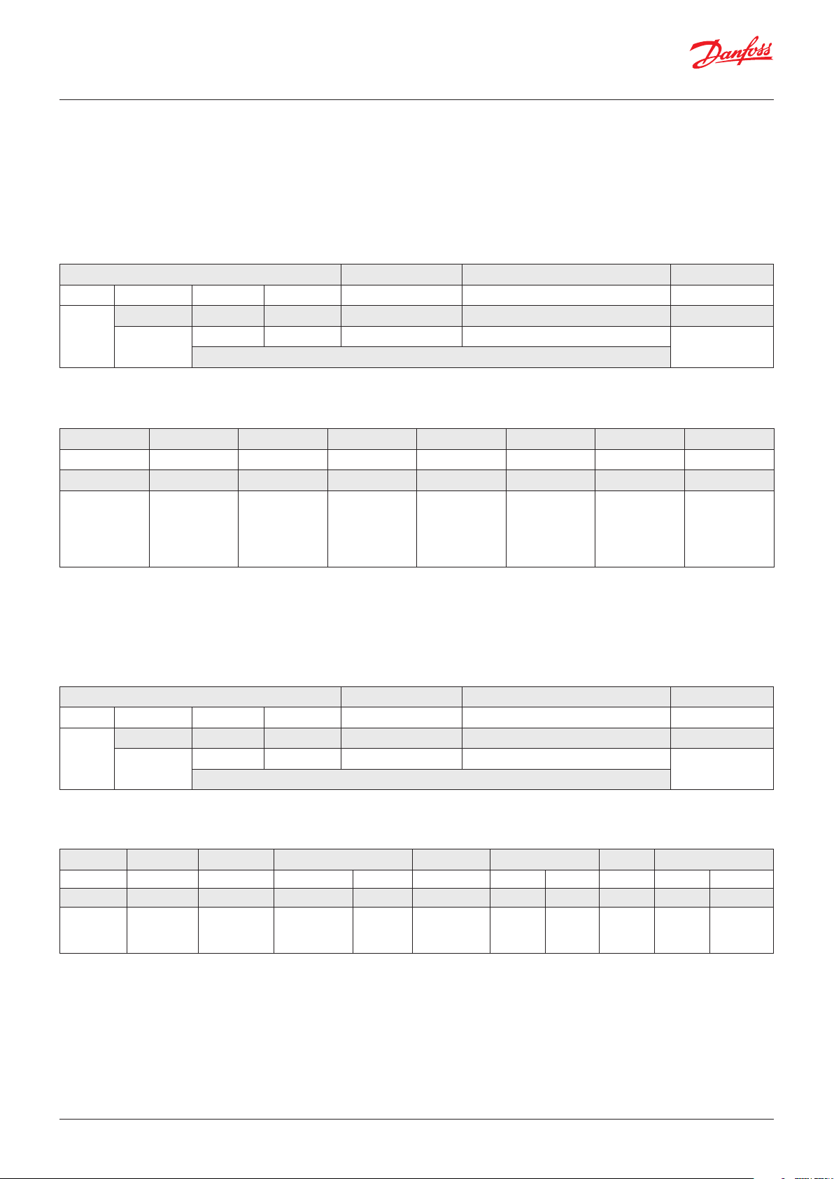
a) Transport Protocol - Connection Management
this message is 9-bit long, it is sent by using the
Broadcast Announce Message of the Transport
Protocol according to PGN 60416 and PGN 60160,
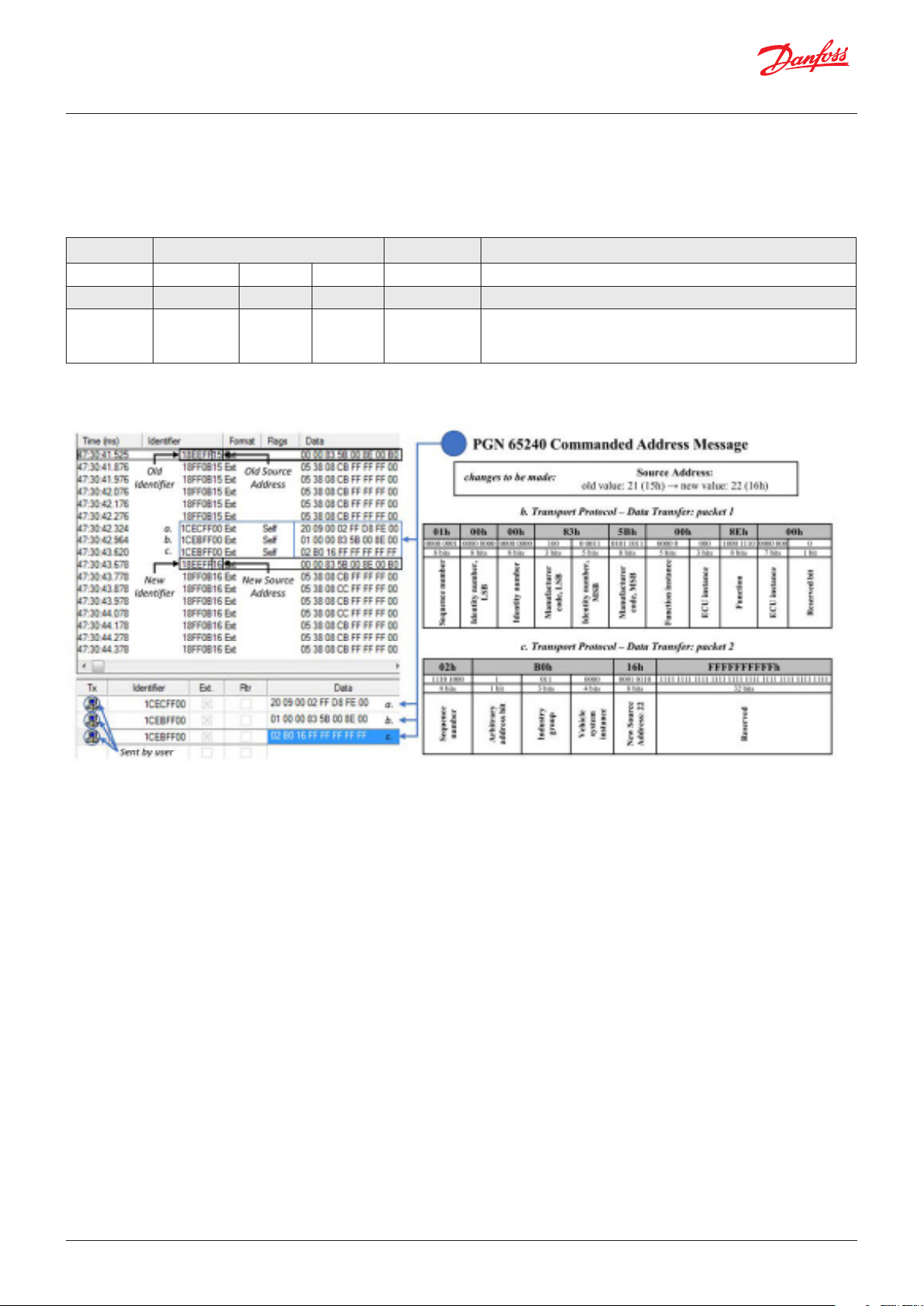
as shown in the example Fig. 6 (page 14).
• Identier: 1CECFFXXh (table11)
• Data eld: Transport Protocol - Connection
Management (table 12).
1Ch ECh FFh XXh
000 111 0 0 1110 1100 1111 1111 xxxx xxxx
3 bits 1 bit 1 bit 8 bits 8 bits 8 bits
-
Priority: 7
Reserved Data page PDU format: PDU1 PDU specic: Destination Address
PGN 60416 (0EC00h)
Source Address
Table 11: PGN 60416 Transport Protocol - Connection Management: Identier denition
20h 09h 00h 02h FFh D8h FEh 00h
0110 0111 0000 1001 0000 0000 0000 0010 1111 1111 1101 1000 1111 1110 0000 0000
8 bits 8 bits 8 bits 8 bits 8 bits 8 bits 8 bits 8 bits
Total
message
size, number
of bytes,
MSB
Total
number of
packets
Reserved
PGN of
the packet
message,
LSB
PGN of the
package
message
PGN of
the packet
message,
MSB
Control
byte
Total
message
size, number
of bytes, LSB
Table 12: PGN 60416 Transport Protocol - Connection Management - Broadcast Announce Message denition
b) Transport Protocol - Data tranfer: Packet 1
• Identier: 1CEBFFXXh (tabel13)
• Data eld: Transport Protocol - Data
Transfer, packet 1 (tabel 14)
1Ch EBh FFh XXh
000 111 0 0 1110 1011 1111 1111 xxxx xxxx
3 bits 1 bit 1 bit 8 bits 8 bits 8 bits
-
Priority: 7
Reserved Data page PDU format: PDU1 PDU specic: Destination Address
PGN 60160 (0EB00h)
Source Address
Table 13: PGN 60160 Transport Protocol - Data Transfer: Identier denition
01h XXh XXh XXh 5Bh XXh XXh XXh
0000 0001 xxxx xxxx xxxx xxxx 100 x xxxx 0101 1011 xxxx x xxx xxxx xxxx xxxx xxx 0
8 bits 8 bits 8 bits 3 bits 5bits 8 bits 5 bits 3 bits 8 bits 7 bits 8 bits
Seequence
number
Ientify
number, LSB
Identify
number
Manufacturer
code, LsB
Identify
number,
MSB
Manufacturer
code, MSB
Function
instance
ECU
instance
Function
Vehicle
system
Reserved
bit
Table 14: PGN 60160 Transport Protocol - Data Transfer:Packet 1
14 | © Danfoss | DCS (im) | 2019.10
AQ304226795410en-0001010 | IC.PS.P21.I2.02
Page 15
Operation guide | DST X510 and DST X520 Rotary position sensor SAE J1939
c) Transport Protocol - Data tranfer: Packet 2
• Identier: 1CEBFFXXh (tabel15)
• Data eld: Transport Protocol - Data
Transfer, packet 2 (tabel 16)
02h XXh XXh FFFFFFFFFFh
0000 0010 x xxx xxxx xxxx xxxx 1111 1111 1111 1111 1111 1111 1111 1111 1111 1111
8 bits 1 bit 3 bits 4 bits 8 bits
Sequence
number
Arbitrary
address
bit
Industry
group
Vehicle
system
instance
New
Source
Address
Reserved
Table 14: PGN 60416 Transport Protocol - Data Transfer:Packet 2
Fig. 6: Example: How to change the Source Address
© Danfoss | DCS (im) | 2019.10
AQ304226795410en-0001010 | IC.PS.P21.I2.02 | 15
Page 16
Danfoss A/S | Industrial Automation | Nordborgvej 81 | DK-6430 Nordborg | Denmark | www.ia.danfoss.com
© Danfoss | DCS (im) | 2019.10
AQ304226795410en-0001010 | IC.PS.P21.I2.02 | 16
 Loading...