

FCM 300
Operating Instructions
Profibus DP V1
FCD 300
VLT
®
2800

FCM 300 / FCD 300 / VLT®2800 / DP V1 PROFIBUS
■ Contents
Introduction
....................................................................................................... 2
Quick Start ......................................................................................................... 4
Profibus DP ............................................................................................................ 4
Baudrate ................................................................................................................ 4
Profibus DP V1 ....................................................................................................... 4
System layout ................................................................................................... 5
Master-controlled frequency converters .................................................................. 5
Bus topology .................................... ............................................................. ......... 6
Features of DP (Distributed Periphery) .................................................................... 6
Rapid Cyclical transmission with PPO using DP ..................................................... 6
Profibus DP V1 ....................................................................................................... 7
Principle of data exchange by Profibus DP V0/DP V1 ............................................. 7
The Profibus Interface .................................................................................. 9
Cable connection FCM 300 .................................................................................... 11
Cable connection FCD 300 .................................................................................... 14
Cable connection VLT 2800 ................................................................................... 17
Profibus DP ........................................................................................................ 20
DP V1 identifications .................................................................................... 30
Parameters ......................................................................................................... 31
Warnings and alarm messages ............................................................... 39
Station address ............................................................................................... 41
Glossary .............................................................................................................. 42
Parameter list .................................................................................................... 43
Index ...................................................................................................................... 50
MG.90.A5.02 - VLT is a registered D anfoss trademark
1
FCM 300 / FCD 300 / VLT®2800 / DP V1 PROFIBUS
■Introduction
Copyrights, L imitation of Liability and Revision Rights.
This publication contains information proprietary to
Danfoss A/S. By accepting and using this manual the
user a grees that the information contained herein will
be used solely for operating equipment of Danfoss A/S
or equipment from other vendors provided that such
equipment is intended for communication with Danfoss
equipment over a PROFIBUS serial communication
link. This publication is protected under the Copyright
laws of Denmark and most other countries.
Danfoss A/S does not warrant that a software program
produced according to the guidelines provided in
this manual will function properly in every physical,
hardware or software environment.
Although Danfoss A/S has tested and reviewed the
documentation within this manual, Danfoss A/S makes
no warranty or representation, either express or implied,
with respect to this documentation, including its quality,
performance, or fitness for a particular purpose.
In no event shall Danfoss A/S be liable for direct,
indirect, special, incidental, or consequential damages
arising out of the use, or the inability to use information
contained in this m anual, even if advised of the
possibility of such damages. In particular, Danfoss
A/S is not responsible for any costs including b ut not
limited to those incurred as a result of lost profits
or revenue, loss or damage of equipment, loss
of computer programs, loss of data, the costs to
substitute these, or any claims by third parties.
Danfoss A/S reserves the right to revise this publication
at any time and to ma ke changes in its contents
without prior notice or any obligation to notify previous
users of such revisions or changes.
When reading through this manual, you will come
across various symbols that require special attention.
The symbols used are the following:
Indicates a general warning.
NB!:
Indicates something to be noted by the reader.
Indicates a high-voltage warning.
PROFIBUS is a registered trademark.
■About this manual
This manual describes the Profibus communication
in the following products:
- FCM 300
- FCD 300
- VLT 2800
The following table shows from which software versions
Profibus DPV1 is supported. The software version can
be read-out in parameter 624 Software versions.
Unit Software version
FCM 300 Not supported
FCD 300 Ver. 1.3x/2.x
VLT 2800 Ver. 2.6x/2.x
This manual gives detailed information of the DP V0
features supported, sufficient for most programming
and maintenance activities. The DP V1 however
is briefly described. For programming purposes
the Profibus DP V1 Design Guide order number
MG.90.EX.YY (X is the version number, and YY the
language code) might be necessary.
It is suggested that readers who are not
completely familiar with PROFIBUS DP or the
profile for frequency converters review the relevant
literature on these subjects.
Even if you are an experienced PROFIBUS programmer,
we suggest that you read this manual in its entirety
before you start programming, since important
information can be found in all chapters.
■Assumptions
This manual assumes that you are using a DANFOSS
FCM 300, FCD 300 or VLT 2800 w ith PROFIBUS. It is
also assumed that you, as a master, are using a PLC or
PC that is equipped with a serial communication card
supporting all the PROFIBUS communication services
required by your application. Further, it is assumed
that all requirements stipulated in the PROFIBUS
standard as well as those set up in the PROFIBUS
frequency converters Profile and its company-specific
implementation PROFIDRIVE, as well as those
pertaining to the frequency converter are strictly
observed as well as all limitations therein fully respected.
MG.90.A5.02 - VLT is a registered Danfoss trademark
2

FCM 300 / FCD 300 / VLT®2800 / DP V1 PROFIBUS
Introduction
The Profibus DP V1 replaces the former
Profibus DP V0 functionality.
Note: The 3MB and 12MB Profibus option are separate
options and have different ordering numbers.
■What you should already know
The DANFOSS PROFIBUS is designed to communicate
with any master abiding by the PROFIBUS DP
standard. It is therefore assumed that you have full
knowledge of the PC or PLC you intend to use as
a master in your system. Any questions pertaining
to hardware or software produced by any other
manufacturer is beyond the scope of this manual
and is of no concern to DANFOSS.
If you have questions about how to set up master
- master communication or communication to
a non-Danfoss slave, the appropriate manuals
should be consulted.
MG.90.A5.02 - VLT is a registered Danfoss trademark
3
FCM 300 / FCD 300 / VLT®2800 / DP V1 PROFIBUS
■Quick start
Details regarding the programming of the usual
frequency converter parameters may be gathered
from the Design Guide for the FCM 300, the
FCD 300 and VLT 2800.
The communication is established by setting the
parameters indicated below.
Details regarding the adjustment of the m aster
are provided by the master manual and by those
chapters in this manual that deal with the particulars
of the VLT PROFIBUS interface.
NB!:
The required GSD file is available on the internet
at http://www.danfoss.com/drives.
■Profibus DP
P
arameter 904
The desired informative data telegram (PPO) is setup
in master configuration. The actual PPO type c an be
read out in P904. The master sends the PPO type in a
configuration telegram in the Profibus DP start phase.
P
arameter 918
This sets the address of the frequency converter
station – one specific address per frequency converter.
For further information, please refer to the section
Station address in this manual.
P
arameter 502 -508
By setting the parameters 502-508 you will be able
to select have to control over the bus.
P
arameter 512
Allows the choice of Control word/Status word type.
For further information, please refer to the section
Control word/Status word this manual.
NB!:
In order to activate a change of parameter
918 the power of the frequency converter
must be cycled.
■Baudrate
The FCM 300, FCD 300 and VLT 2800 adjust
automatically to the Baudrate configurated
from the master.
NB!:
When configuring the PPO types, a distinction
is made between module consistency
andwordconsistency:
Module consistency means that a specific portion
of the PPO is defined as a connected module. The
parameter interface (PCV, length of 8 bytes) of the
PPO always has m odule consistency.
Word consistency means that a specific portion
of the PPO is divided into individual data sectors
of word length (16 bits).
The process data of the PPO may have either module
consistency or word consistency, as desired.
Some PLCs, such as Siemens S7, require special
functions to call m odules that are longer than 4
bytes (in the case of Siemens: "SFC", see master
manual). This means that the PCV interfaces of
the PPOs c an only be called through the SFC
functions in the case of Siemens (S7).
■Profibus DP V1
A detailed description of the DV V1 features supported
can be found in the "Profibus DP V1 Design
Guide" order number MG.90.EX.YY.
Further specifications might be helpful:
- Technical Guide "PROFIBUS -DP Extensions to EN
50170 (DPV1)" V2.0, April 1998, Order no. 2.082
- Draft PROFIBUS Profile PROFID RIV E Profile Drive
Technology V3.0 September 2000, Order no. 3.172
MG.90.A5.02 - VLT is a registered Danfoss trademark
4

FCM 300 / FCD 300 / VLT®2800 / DP V1 PROFIBUS
System
layout
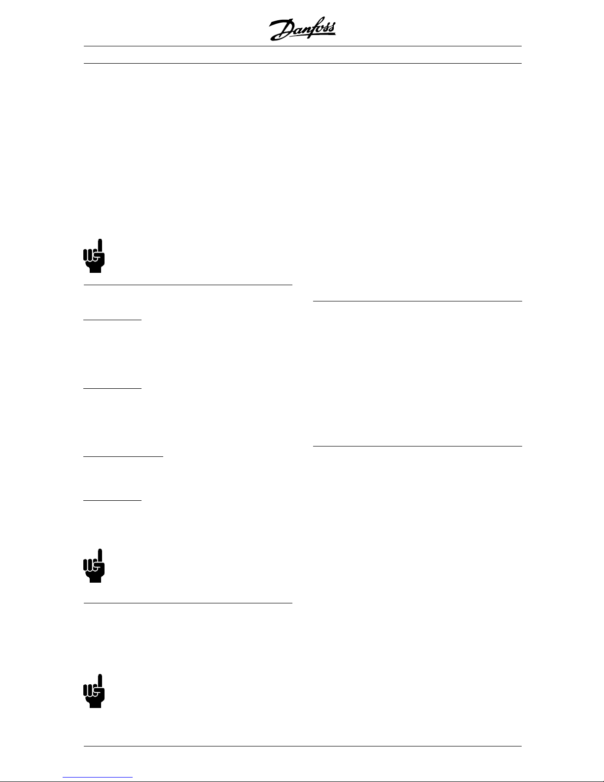
■Master-controlled frequency converters
The PROFIBUS Fieldbus was designed to give you
unprecedented flexibility and command over your
controlled system. The PROFIBUS will perform as an
integrated part of your frequency converter, giving you
access to all parameters relevant to your application.
The frequency converter will always act as a slave, and
together with a master it can exchange a multitude
of information and commands. Control signals such
as speed reference, start / stop of motor, reverse
operation, etc. are transmitted from the master in
the form of a telegramme. The frequency converter
acknowledges receipt by transmitting status signals,
such as running, on reference, motor stopped and so
on to the master. The frequency converter may also
transmit fault indications, alarms and warnings to the
master, such as Overcurrent or Phaseloss.
The PROFIBUS communicates in accordance with the
PROFIBUS field bus standard, EN 50170, part 3. It
can thus exchange data with all masters that me et
this standard; however, this does n ot mean that all
services ava ilable in the PROFIDRIVE profile standard
are supported. The PROFIBUS profile for frequency
converters (version 2 and partly version 3, PNO) is a
part of PROFIBUS which supports only those services
that concern applications with speed control.
C
ommunication partners
In a control system the frequency converter
will always act as a slave, and as such it may
communicate with a single master or multiple masters
depending on the nature of the application. A
master may be a PLC or a PC that is equipped
with a PROFIBUS communication card.
MG.90.A5.02 - VLT is a registered Danfoss trademark
5
FCM 300 / FCD 300 / VLT®2800 / DP V1 PROFIBUS
■Bus topology
S
ingle master operation with DP V0
-Singlemaster
- PLC communicates with telegrams of
constant length
- Fits to t ime critical requirements
Cyclical transmis sion (PLC)
1. Setpoint transmission
2. Actual value feedback
3. New set points computed
4. New set point transmission
5. Parameter Read - using PCV channel
6. Parameter Write - using PCV channel
7. Read parameter description - using PCV channel
■Features of DP (Distributed Periphery)
- Is used by several PLC manufacturers for remote
peripheral I/O communication.
- Supports cyclical communication.
- SRD (Send Receive Data) service gives fast
cyclical exchange of process data between
master and slaves.
- Freeze and synchronize function is supported.
- Fixed data structure.
- Fixed telegramme size.
- Occupies I/O memory space in PLC proportional
to the number of slaves employed, which may
limit the number of participants. Additional data
require additio nal I/O memory space.
DP should be used when fast cyclical process control
is needed. Such a concept would typically call
for single master operation with a limited number
of slave stations. A high number of slaves will
increase the system response time.
This could also be the case where control
loops are closed over the bus. As a very fast
alternativeitisofcoursepossibletoclosethe
control loop outside the bus.
■Rapid Cyclical transmission with PPO using DP Control of the drives during normal operation is often
very time critical, but it involves very few data, such
as control commands and speed reference. DP is
optimized for fast cyclical communication.
Parameter up-/downloads can be achieved by
using the PCV part of the so-called Parameter Process data Objects - PPO types 1, 2 or 5, see
drawing in paragraph PPO description.
MG.90.A5.02 - VLT is a registered Danfoss trademark
6
FCM 300 / FCD 300 / VLT®2800 / DP V1 PROFIBUS
System
layout
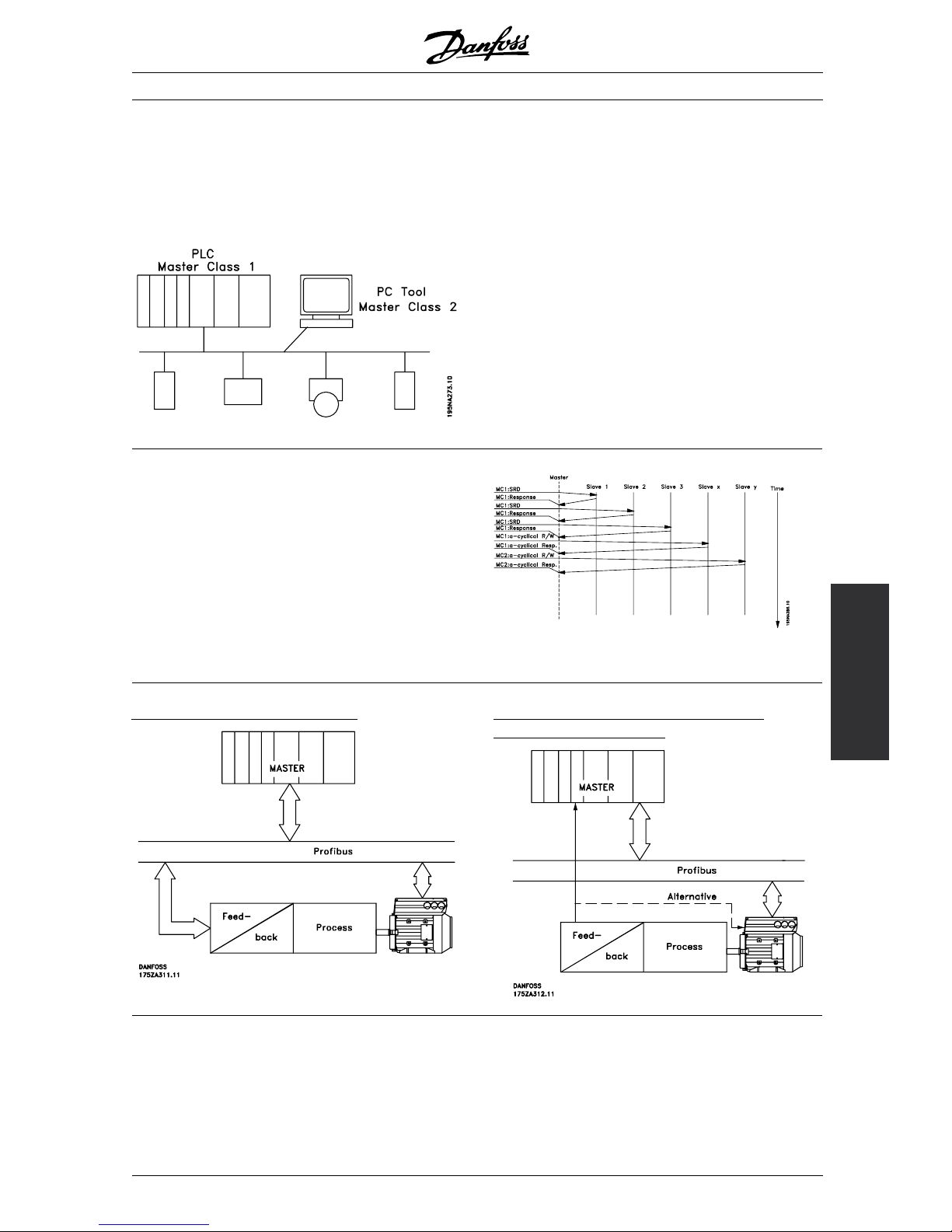
■Profibus DP V1
The Profibus DP extension DP V1 offers additional
to the cyclical data communication an acyclica l
communication. This feature can be used by a
DP master type 1 (e.g. PLC), as well as a DP
master type 2 (e.g. PC tool).
Features of a Master type 1 connection
- Cyclical data exchange (DP V0).
- Acyclical read/write on parameters.
The acyclical connection is fixed, and can not
be changed during operation.
Features of a Master type 2 connection:
- Initiate / Abort acyclical connection.
- Acyclical read/write on parameters.
The acyclical connection can dynamically be
established (Initiate) or removed (Abort) even when
a master class 1 is active on the network.
The DP V1 acyclical connection can be used
for general parameter access as an alternative
to the PCV parameter channel.
■Principleofdata exchange by ProfibusDPV0/DPV1
InaDPcycletheMC1willfirstupdatethecyclical
process da ta for all slaves in the system. After that
the MC 1 has the possibility of sending one acyclical
message to one slave. If a MC 2 is connected,
the MC 1 will handle over the Token to MC 2 who
now is a loud to send one acyclical message to one
slave. After that, the token is handled back to the
MC 1, and a new DP cycle is started.
MC1: Master Class 1
Closing the control loop over the bus Closing the control loop outside the fieldbus
for extremely fast feed-back
MG.90.A5.02 - VLT is a registered Danfoss trademark
7
FCM 300 / FCD 300 / VLT®2800 / DP V1 PROFIBUS
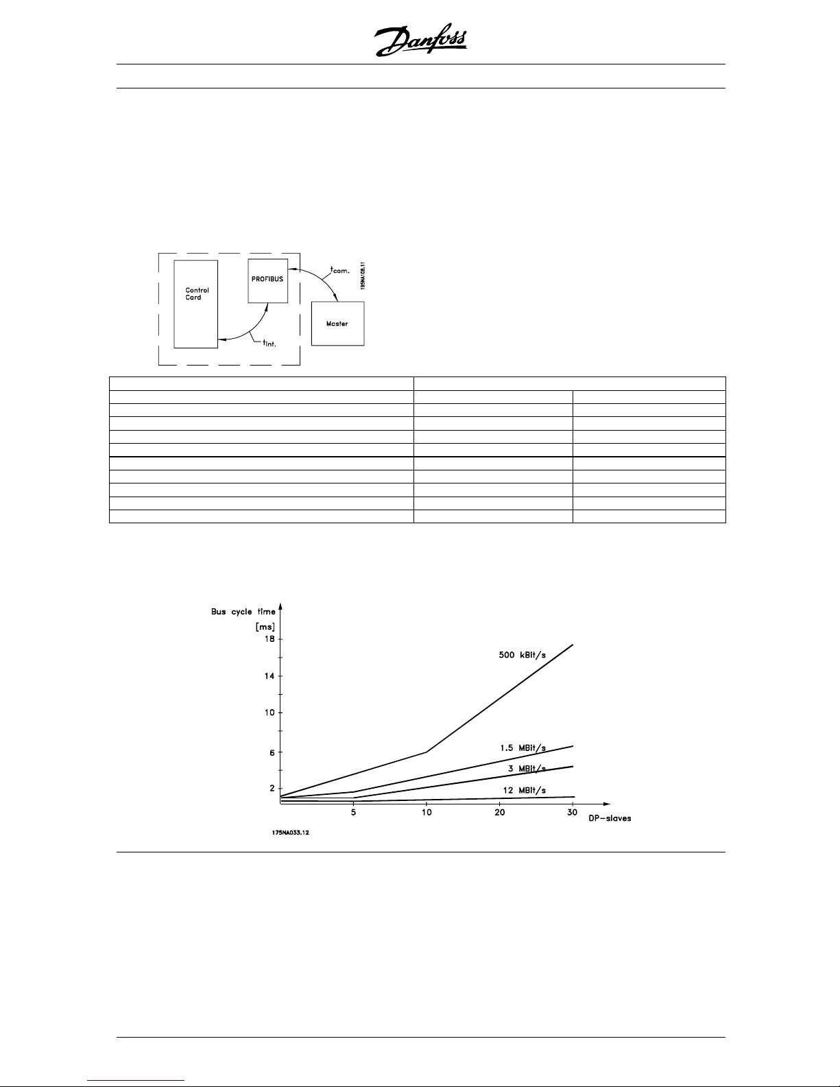
■FCM 300/FCD 300/VLT 2800 response time
The update time via the prodibus connection can be
divided in two parts: 1) The communication time, which
is the time it takes to transmit data from the master to
the slave (FCM 300/FCD 300/VLT 2800 with profibus),
and 2) the internal update time, which is the time it
takes to transmit data between the FCM 300/FCD
300/VLT 2800 control card and the profibus.
Communication time (t
com
) depends on the actual
transmission speed (baudrate) and the type of master
in use. The minimum obtainable communication
time with the FCM 300/FCD 300/VLT 2800 with
PROFIBUS is approx. 100 msec per slave, when
using DP communication with 4 bytes of data (PPO
type 3) at 3 Mbaud. More data or lower transmission
speed will increase the communication time.
The internal update time (t
int
) depends on the type
of data in question as there are different channels for
the data transfer where time critical data e.g. control
word has highest priority. The internal update time for
the different types of data are stated below.
Update tim e, t
int
Data FCD 300/ VLT 2800 FCM 300
Control word/Main reference (part of PPO) Max. 26 msec. Max. 65 msec.
Status word/Actual output frequency (part of PPO) Max. 26 msec. Max. 65 msec.
Parameter read (PCD 1-8) 40 msec. 40 msec.
Parameter write (PCD 1-2) 160 msec. 160 msec.
Parameter write (PCD 3-4) 320 msec. 320 msec.
Parameter write (PCD 5-8) 640 msec. 640 msec.
Parameter read (PCV) 41 msec. 41 msec.
Parameter write (PCV) 40 msec. 40 msec.
Acyclical data (single read, write) - 40 msec.
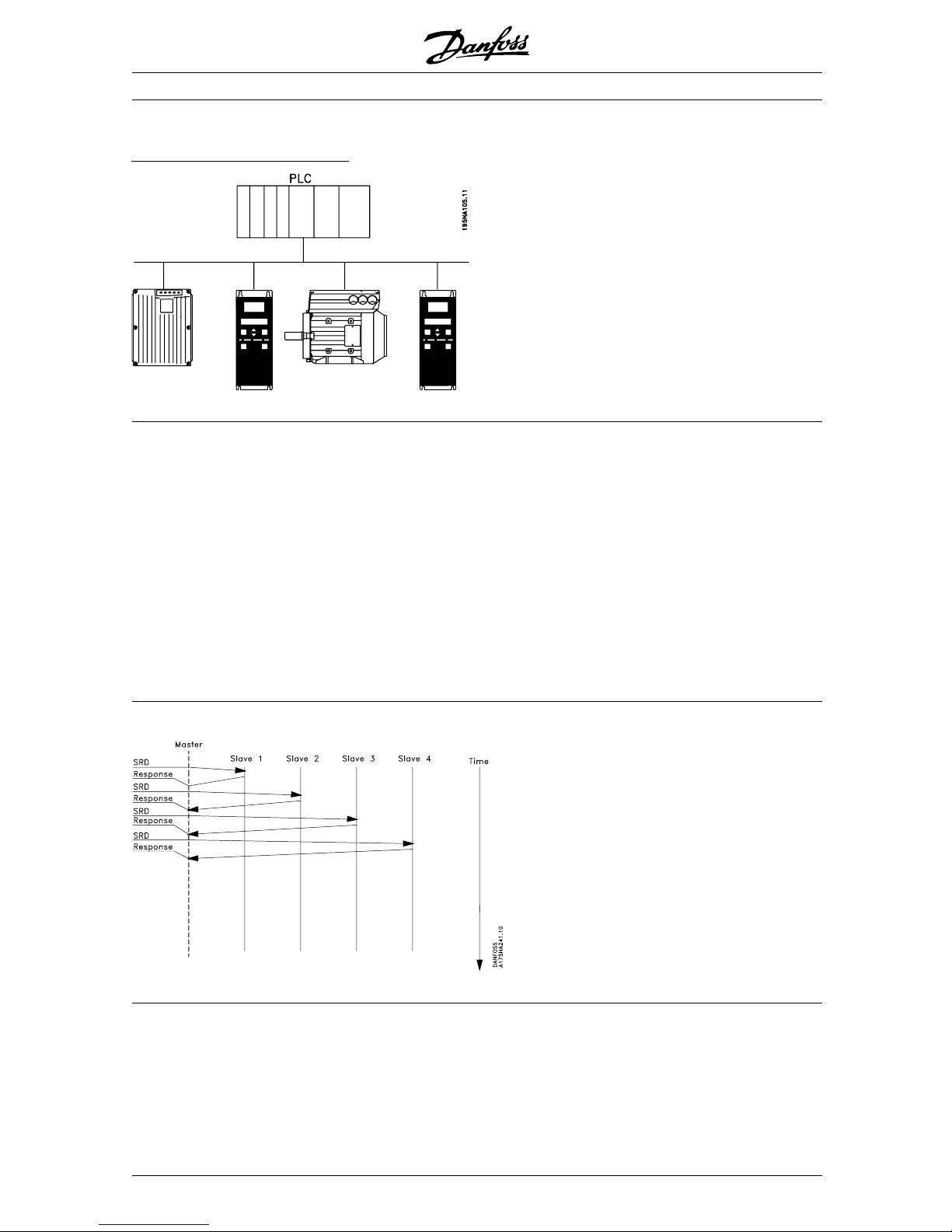
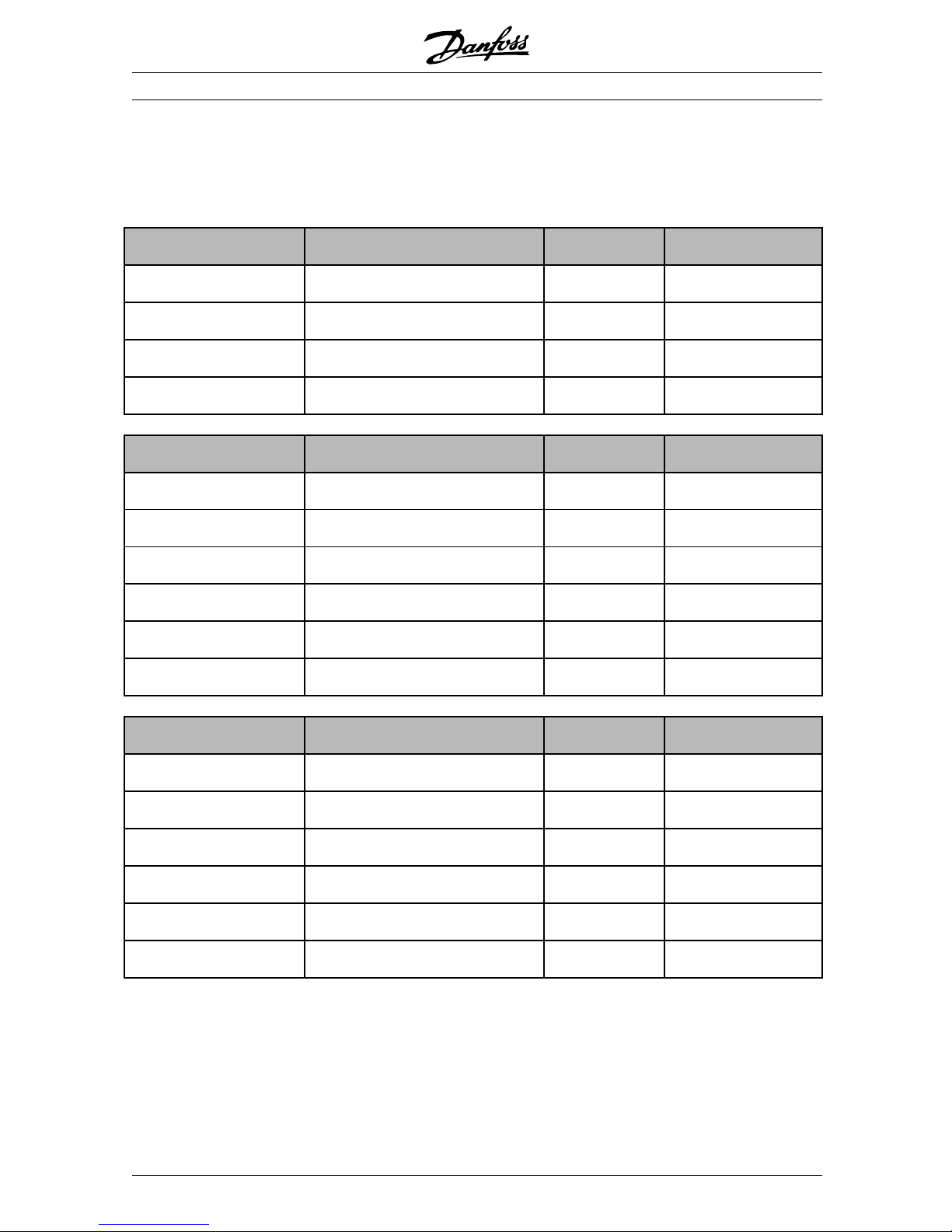
■System update time
The system update time is the time it takes to
update all the slaves in the network when using
cyclical communication. The drawing below
shows the value which is obtainable in theory
at 2 input and 2 output bytes.
MG.90.A5.02 - VLT is a registered Danfoss trademark
8
FCM 300 / FCD 300 / VLT®2800 / DP V1 PROFIBUS
The Profibus
Interface
The Profibus Interface
The total drop cable length for one segment is
limited as stated in the table below.
Drop cable length
Transmission speed Max. drop cable lenth
per segment [m]
9.6-93.75 kBaud 96
187.5 kBaud 75
500 kBaud 30
1.5 mBaud 10
3-12 MBaud none
The length statements in the tables above
are valid provided that bus cable with the
following properties
is used:
- Impedance: 135 to 165 ohm at a measuring
frequency from 3 to 20 MHz
- Resistance: < 110 ohm/km
- Capacity: < 30 pF/m
- Damping: max. 9 dB over the whole wire
length
- C ross section: max. 0.34 mm
2
, corresponding
to AWG 22
- Cable type: twisted in pairs,
1x2,or2x2,or1x4wires
- Screening: Copper-braided screen or
braided screen and foil screen
It is recommended to use the same cable type in the
entire network to avoid impedance mismatch.
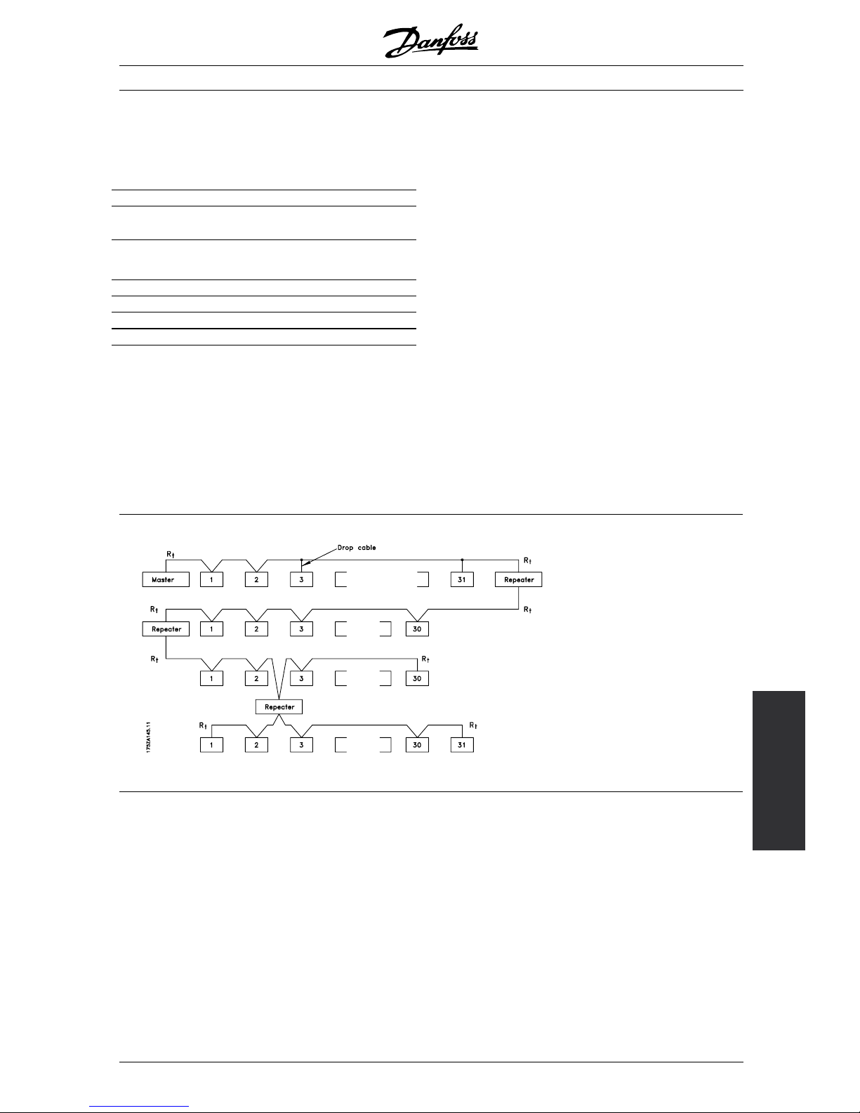
The numbers on the following drawing indicate the
maximum number of stations in each segment. They
are not the station addresses as each station in the
network must have a unique address.
Segment 1
Segment 2
Segment 3
Segment 4
Rt= termination resistors
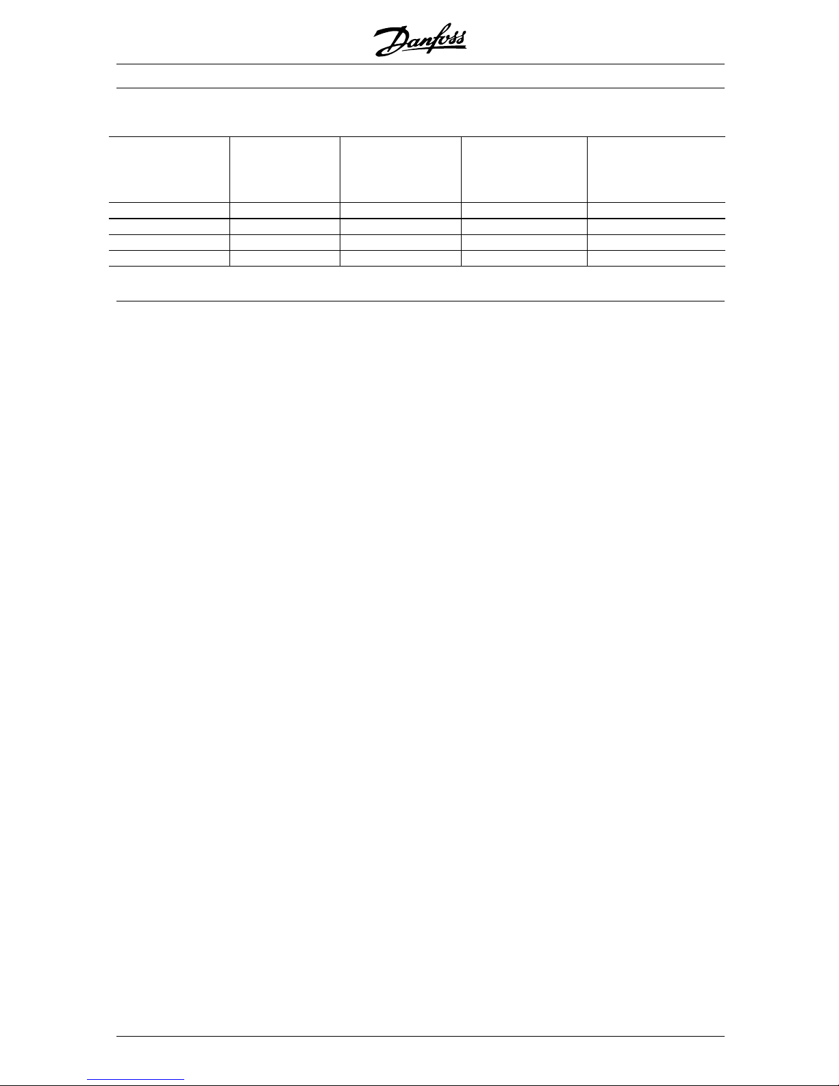
■Cable lengths/ number of nodes
The maximum cable length in one segment is
depending on the transmission speed. The total
cable length includes drop cables if any. A drop
cable is the connection from the main bus cable
to each node if a T-connection is used instead of
connecting the main bus cable directly to the nodes,
see drop cable ength. The table below shows the
maximum allowed cable length and maximum number
of nodes/frequency converters with 1, 2, 3 and 4 bus
segments. Note that a repeater is a node in both of the
two segments it connects. The number of frequency
converters is based on a single master system. If
there are more masters the number of frequency
converters must be reduced correspondingly.
MG.90.A5.02 - VLT is a registered Danfoss trademark
9
FCM 300 / FCD 300 / VLT®2800 / DP V1 PROFIBUS
Max. total bus cable length
Transmission speed 1segment:
32 nodes
(31 VLT)
[m]
2segments:
64 nodes
(1 repeater, 61 VLT)
[m]
3segments:
96 nodes
(2 repeaters, 91 VLT)
[m]
4segments:
128 nodes
(3 repeaters, 121 VLT)
[m]
9.6-187.5 kBaud 1000 2000 3000 4000
500 kBaud 400 800 1200 1600
1.5 MBaud 200 400 600 800
3-12MBaud 100 200 300 400
MG.90.A5.02 - VLT is a registered Danfoss trademark
10

FCM 300 / FCD 300 / VLT®2800 / DP V1 PROFIBUS
The Profibus
Interface
■Physical connection
The PROFIBUS is connected to the bus line
via X100, terminals 1 and 2.
It is recommended to use a master with a
galvanic isolated bus driver and with over voltage
protection (e.g. zenerdiode).
E
MC precautions
The following EMC precautions are recommended to
obtain interference free operation of the PROFIBUS
network. Additional information on E MC can be found
in the design guide on the FCM 300 (MG.03.BX.02).
Please also consult the manual of the PROFIBUS
master for further installation guidelines.
■Connection of the cable screen
The screen of the PROFIBUS cable must always
be connected to ground at both ends, that means
the screen must be connected to ground in all
stations connected to the PROFIBUS network. It
is very important to have a low impedance ground
connection of the screen, also at high frequencies.This
can be obtained by connecting the surface of the
screen to ground, for example by means of a cable
clamp or a conductive cable gland.
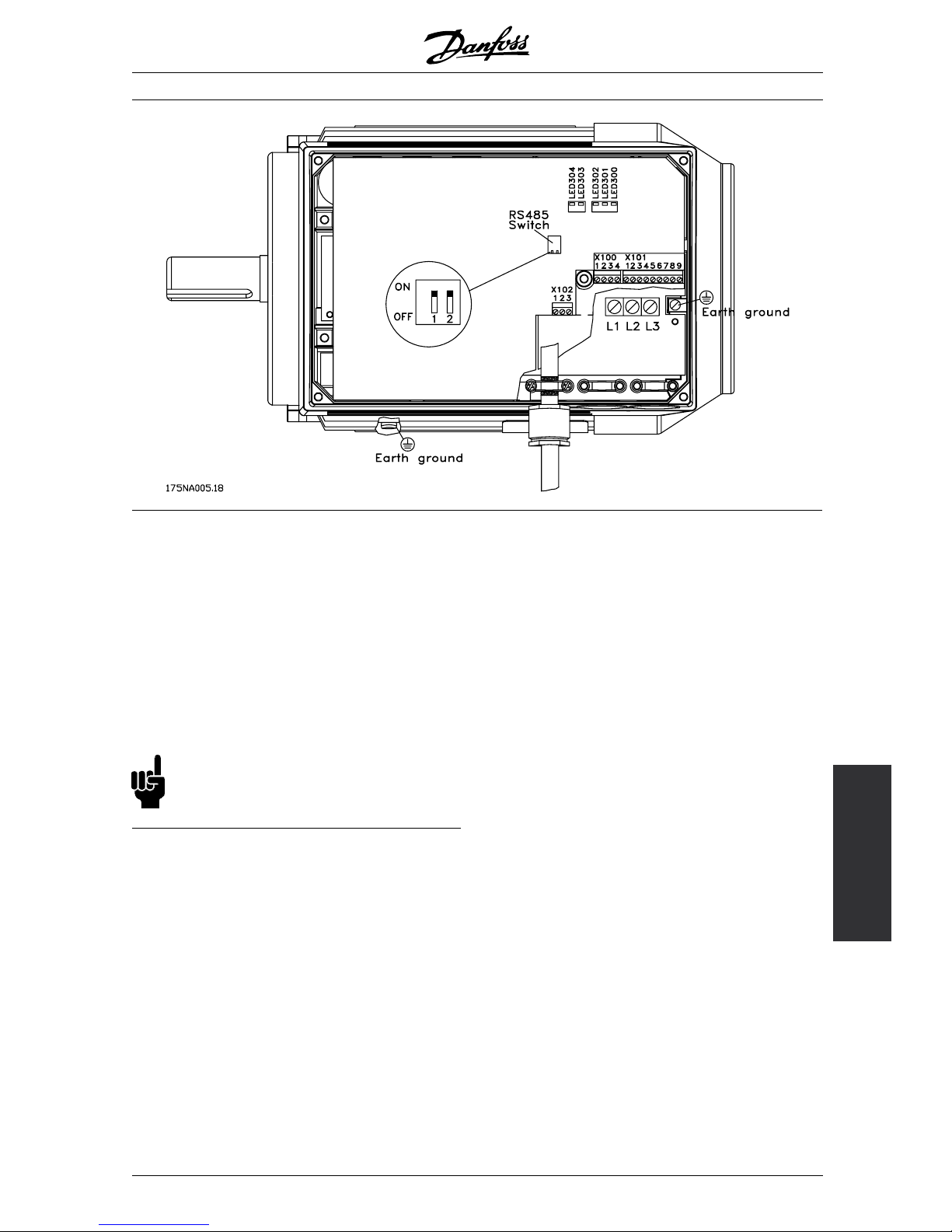
The FCM 300 Series is provided with different clamps
and brackets to enable a proper ground connection of
the P ROFIBUS cable screen. The screen connection
is shown in the following drawing.
NB!:
Relevant national and local regulations,
for example regarding protective earth
connection, must be observe d.
■Cable connection F CM 300
The PROFIBUS communica tion cable must be kept
away from motor and brake resistor cables to avoid
coupling of high frequency noise from one cable to
the other. Normally a distance of 200 mm is sufficient,
but it is generally recommended to keep the greatest
possible distance between the cables, especially where
cables are running in parallel over long distances.
If the PROFIBUS cable has to cross a motor and
braking resistance cable, it should occur at a 90° angle.
■Earth connection
It is important that all stations connected to the
PROFIBUS network are connected to the same
earth potential. The earth connection must have
a low HF (high frequency) impedance. This c an
be achieved by connecting a large surface area of
the cabinet to earth, for example by mounting the
FC motor on a conductive rear plate.
Especially when having long distances between the
stations in a PROFIBUS network it can be necessary to
use additional potential equalizing cables, connecting
the individual stations to the same earth potential.
MG.90.A5.02 - VLT is a registered Danfoss trademark
11
FCM 300 / FCD 300 / VLT®2800 / DP V1 PROFIBUS
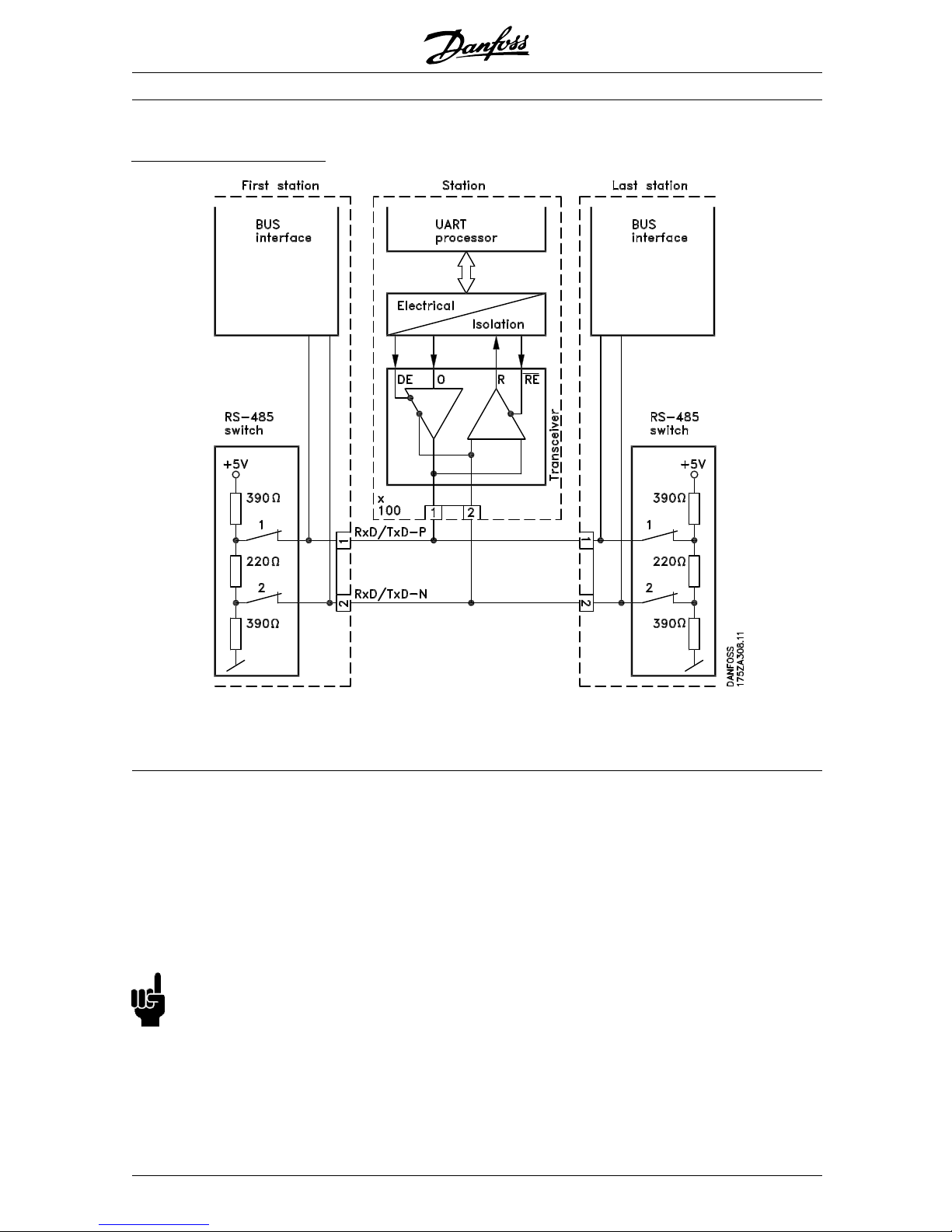
The bus termination - FCM 300
1 = RxD/TxD-P∼ (red cable) 2 = RxD/TxD-N∼ (green cable)
It is essential that the bus line is terminated properly.
A mismatch of impedance may result in reflections
onthelinethatwillcorruptdatatransmission.
- The PROFIBUS is provided with a suitable
termination which may be activated by the switches
of the RS485 switch block located just to the left of
the terminal block X100 (see drawing below). The
switches should be o n to terminate the bus.
NB!:
The switches should never be left in opposite
positions. They should either both be
ON or both be OFF!
- Most masters and repeaters are equipped
with their own termination.
- If an external termination circuit consisting of three
resistors is connected to the bus line a 5 V d.c.
power supply must be used, please note that this
must be galvanically isolated from the a.c. line.
MG.90.A5.02 - VLT is a registered Danfoss trademark
12
FCM 300 / FCD 300 / VLT®2800 / DP V1 PROFIBUS
The Profibus
Interface
■FCM 300 LEDs
There are 2 LEDs on the PROFIBUS:
LED303: Lights up when the card is initialized
and ready to communicate. It will
flash while auto baudrate detection
is attemptin g to d etect the actual
baudrate.
LED304: Lights up when the card is
communicating, depending on
baudrate.
NB!:
A high baudrate results in dim light in LED304.
MG.90.A5.02 - VLT is a registered Danfoss trademark
13
FCM 300 / FCD 300 / VLT®2800 / DP V1 PROFIBUS
■Physical connection FCD 300
The PROFIBUS is connected to the bus line
via, terminals 68 and 69.
It is recommended to use a master with a
galvanic isolated bus driver and with over voltage
protection (e.g. zenerdiode).
E
MC precautions
The following EMC precautions are recommended to
obtain interference free operation of the PROFIBUS
network. Additional information on E MC can be found
in the design guide on the FCD 300 (MG.04.AX.02).
Please also consult the manual of the PROFIBUS
master for further installation guidelines.
■Connection of the cable screen
The screen of the PROFIBUS cable must always be
connected to ground at both ends, that means the
screen must be connected to ground in all stations
connected to the PROFIBUS network. It is very
important to have a low impedance ground connection
of the screen, also at high frequencies.This can be
obtained by connecting the surface of the screen to
ground, for example by means of a cable clamp.
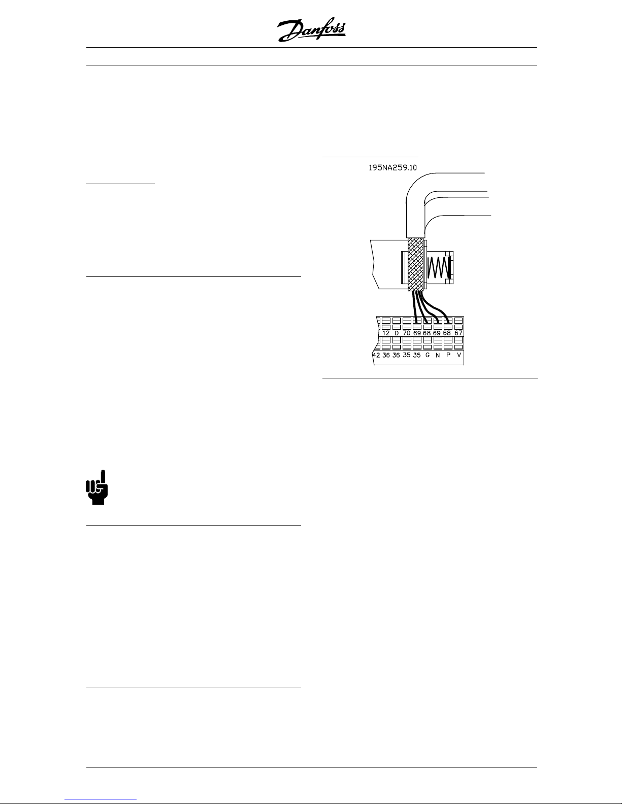
The FCD 300 Series is provided with a sprin g loaded
clamp to enable a proper ground connection of the
PROFIBUS cable screen. The screen connection
is shown in the following drawing.
NB!:
Relevant national and local regulations,
for example regarding protective earth
connection, must be observe d.
■Cable connection F CD 300
The PROFIBUS communica tion cable must be kept
away from motor and brake resistor cables to avoid
coupling of high frequency noise from one cable to
the other. Normally a distance of 200 mm is sufficient,
but it is generally recommended to keep the greatest
possible distance between the cables, especially where
cables are running in parallel over long distances.
If the PROFIBUS cable has to cross a motor and
braking resistance cable, it should occur at a 90° angle.
■Earth connection FCD 300
It is important that all stations connected to the
PROFIBUS network are connected to the same
earth potential. The earth connection must have
a low HF (high frequency) impedance.
Especially when having long distances between the
stations in a PROFIBUS network it can be necessary to
use additional potential equalizing cables, connecting
the individual stations to the same earth potential.
C
onnecting the bus line
MG.90.A5.02 - VLT is a registered Danfoss trademark
14
FCM 300 / FCD 300 / VLT®2800 / DP V1 PROFIBUS
The Profibus
Interface
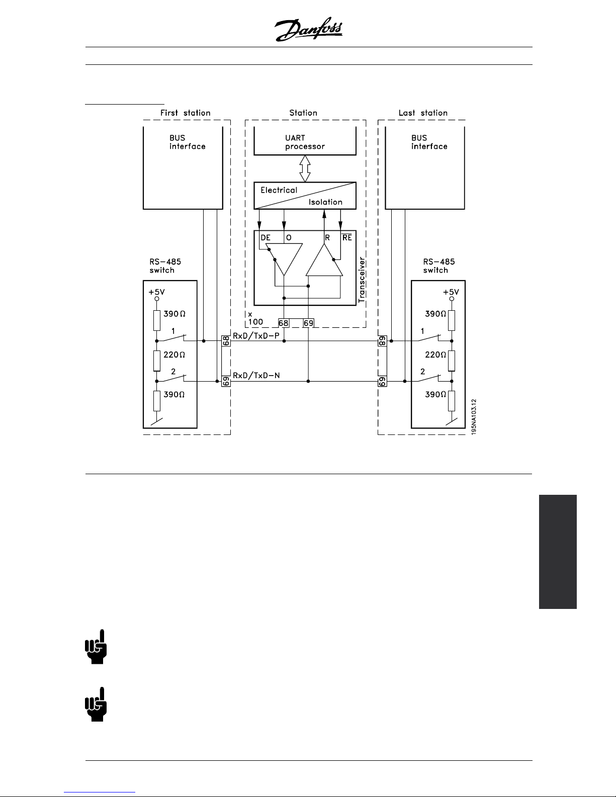
The bus termination
68 = RxD/TxD-P
∼ (red cable)
69 = RxD/TxD-N
∼ (green cable)
It is essential that the bus line be terminated properly.
A mismatch of impedance may result in reflections
onthelinethatwillcorruptdatatransmission.
- The PROFIBUS is provided with a suitable
termination which may be activated by the switches
of the RS485 switch block located on the bottom
of the electronics part (see drawing below). The
switches should be o n to terminate the bus.
- Most masters and repeaters are equipped
with their own termination.
NB!:
The switches should never be left in opposite
positions. They should either both be
ON or both be OFF!
NB!:
Is 126 or 127 selected the address is setting
via P 918, refer to chapter station address.
- If an external termination circuit consisting of three
resistors is connected to the bus line a 5 V d.c.
power supply must be used, please note that this
must be galvanically isolated from the a.c. line.
MG.90.A5.02 - VLT is a registered Danfoss trademark
15

FCM 300 / FCD 300 / VLT®2800 / DP V1 PROFIBUS
Switch 1 2 3 4 5 6 7 8
Address Switch s etting
0 OFF OFF OFF OFF OFF OFF OFF X
1 ON OFF OFF OFF OFF OFF OFF X
2 OFF ON OFF OFF OFF OFF OFF X
....125 ON ON ON ON ON OFF ON X
126 ON ON ON ON ON ON OFF X
127
(default)
ON ON ON ON ON ON ON X
■FCD 300 LEDs
The bus LED on the front:
LCP stop mode or
Operation site = local
Remote and bus control
Baud rate search LED is flashing LED is flashing
Baud rate found and drive is ready
to get and set cyclical data
Flashing 1.5 sec. On
Baud rate found and drive is not
set to state receive/send cyclical
data
Flashing 1.5 sec. Flashing: 2 sec. off, 320 ms on
Only acyclical communication (no
cyclical data)
Flashing 1.5 sec. Flashing: 2 sec. off, 320 ms on
In case that a cyclical communication is established,
the LED is on. If only a acyclical communication with
a master 2 is activ e the LED is flashing.
MG.90.A5.02 - VLT is a registered Danfoss trademark
16

FCM 300 / FCD 300 / VLT®2800 / DP V1 PROFIBUS
The Profibus
Interface
■Physical connection VLT 2800
The PROFIBUS is connected to the bus line
via, terminals 68 and 69.
It is recommended to use a master with a
galvanic isolated bus driver and with over voltage
protection (e.g. zenerdiode).
E
MC precautions
The following EMC precautions are recommended to
obtain interference free operation of the PROFIBUS
network. Additional information on E MC can be found
in the design guide on the VLT 2800 (MG.28.EX.02).
Please also consult the manual of the PROFIBUS
master for further installation guidelines.
■Connection of the cable screen
The screen of the PROFIBUS cable must always be
connected to ground at both ends, that means the
screen must be connected to ground in all stations
connected to the PROFIBUS network. It is very
important to have a low impedance ground connection
of the screen, also at high frequencies. This can be
obtained by connecting the surface of the screen to
ground, for example by means of a cable clamp.
The VLT 2800 Series is provided with different
clamps to enable a proper ground connection of the
PROFIBUS cable screen. The screen connection
is shown in the following drawing.
NB!:
Relevant national and local regulations,
for example regarding protective earth
connection, must be observe d.
■Cable connection VLT 2800
The PROFIBUS communica tion cable must be kept
away from motor and brake resistor cables to avoid
coupling of high frequency noise from one cable to
the other. Normally a distance of 200 mm is sufficient,
but it is generally recommended to keep the greatest
possible distance between the cables, especially where
cables are running in parallel over long distances.
If the PROFIBUS cable has to cross a motor and
braking resistance cable, it should occur at a 90° angle.
■Earth connection
It is important that all stations connected to the
PROFIBUS network are connected to the same
earth potential. The earth connection must have
a low HF (high frequency) impedance. This c an
be achieved by connecting a large surface area of
the cabinet to earth, for example by mounting the
VLT 2800 on a conductive rear plate.
Especially when having long distances between the
stations in a PROFIBUS network it can be necessary to
use additional potential equalizing cables, connecting
the individual stations to the same earth potential.
MG.90.A5.02 - VLT is a registered Danfoss trademark
17

FCM 300 / FCD 300 / VLT®2800 / DP V1 PROFIBUS
The bus termination
68 = RxD/TxD-P∼ (red cable) 69 = RxD/TxD-N∼ (green cable)
It is essential that the bus line be terminated properly.
A mismatch of impedance may result in reflections
onthelinethatwillcorruptdatatransmission.
- The PROFIBUS is provided with a suitable
termination which may be activated by the switches
of the RS485 switch block located just above the
terminal block 67-70 (see drawing below). The
switches 1 and 2 should be on to terminate the bus.
- Most masters and repeaters are equipped
with their own termination.
- If an external termination circuit consisting of three
resistors is connected to the bus line a 5 V d.c.
power supply must be used, please note that this
must be galvanically isolated from the a.c. line.
MG.90.A5.02 - VLT is a registered Danfoss trademark
18

FCM 300 / FCD 300 / VLT®2800 / DP V1 PROFIBUS
The Profibus
Interface
■VLT 2800 LEDs
There are 2 LEDs on the PROFIBUS:
LD851: Lights up when the card is initialized and ready
to communicate. It will flash while auto baudrate
detection is attemp tin g to detect the ac tual baudrate .
LD852: Lights up when the card is communicating,
depending on baudrate.
NB!:
A high baudrate results in d
im light in LD852.
MG.90.A5.02 - VLT is a registered Danfoss trademark
19

FCM 300 / FCD 300 / VLT®2800 / DP V1 PROFIBUS
Profibus DP
■DP communication relations
Communication according to PROFIBUS DP, i.e. EN
50170 part 3, is supported. Consequently a master
that supports PROFIBUS DP must be used.
By DP communication one of the parameter-process
data objects (PPO’s) described below must be used.
■PPO description
A special feature of the PROFIBUS Profile for frequency
converters is the communication object called a PPO,
meaning Parameter-Process Data Object.
The PPO is well suited for fast cyclical data
transfer, and may, as the name implies, carry both
process data and parameters.
The selection of PPO type is made according
to the master configuration.
A PPO may consist of a parameter part and process
data part. The parameter part can be used for reading
and/or updating the parameters one by one. The
process data part consists of a fixed part (4 bytes)
and a parametrable part (8 or 16 bytes). In the fixed
part control word and speed reference are transfered
to the frequency converter while status word and
actual output frequency feedback are transfered
from the frequency converter. In the parametrable
part the user chooses which parameters ha ve to
be transfered to (parameter 915) and which from
(parameter 916) the frequency converter.
PPO. Parameter-Process Data Object
By DP one of the following shown PPO’smustbeused:
PCD: Process Da
ta
PCV: Parameter-
Characteristics-Value
PCA: Parameter-C
haracteristics (Bytes 1, 2)
(PCA handling see sec tion PCA handling)
IND: Subindex (Byte 3), (Byte 4 is not u sed)
PVA: Parameter value (Bytes 5 to 8)
CTW: Control word see section Control word
STW: Status word see section Status word
MRV: Main reference value
MAV: Main actual value (Actual outp ut frequency)
MG.90.A5.02 - VLT is a registered Danfoss trademark
20
FCM 300 / FCD 300 / VLT®2800 / DP V1 PROFIBUS
Profibus
DP
■PCA handling
The PCA portion of the PPO types 1, 2 and 5
will handle a number of tasks. The master may
control and supervise parameters and request a
response from the slave, while the slave, apart
from responding to a request from the master may
transmit a s pontaneous message.
Requests and responses is a handshake procedure
and cannot be batched, m eaning that if the master
sends out a Read/write request, it has to wait for the
response, before it sends a new request. The request
or response data value will be limited to max. 4 bytes,
which implies that text strings are not transferable. For
further information, please see section Examples .
PCA - Parameters Characteristics
15 14 13 12 11 109876543210
RC SMP PNU
RC: Request /respons Characteristics (Range 0..15)
SPM: Toggle-Bit for Spontaneous Messages
PNU: Parameter # (Range 1..1999)
Request/response handling
The RC portion of the PCA word defines the
requests that may be issued from the master to
the slave as well as what other portions of the
PCV (IND and PVA) are involved.
The PVA portion will transmit word-size parameter
values in bytes 7 and 8, while long word size
valuesrequirebytes5to8(32bits).
If the R esponse / Request contains array elements,
the IND will carry the A rray Subindex. If parameter
descriptions are involved, the IND will hold the Record
Subindex of the Parameter description.
RC content
Request Function
0Norequest
1 Request parameter value
2 Change parameter value (word)
3 Change parameter value (long word)
4 Request description element
5 Change description element
6 Request parameter value (array)
7 Change parameter value (array word)
8 Change parameter value (array long word)
9 Request number of array elements
10-15 Not used
Response
Function
0Noresponse
1 Transfer parameter value (word)
2 Transfer parameter value (long word)
3 Transfer description element
4 Transfer parameter value (array word)
5 Transfer parameter value (array long word)
6 Transfer number of array elements
7 Request rejected (incl. fault #, see below)
8 Not serviceable by PCV interface
9 Spontaneous message (word)
10 Spontaneous message (long word)
11 Spontaneous message (array word)
12 Spontaneous message (array long word)
13-15 Not used
If the slave rejects a request from the master, the
RC word in the PPO-read will indicate this by
assuming the value 7. The fault # will be carried
by bytes 7 and 8 in the PVA element.
Fault # Interpretation
0 Illegal PNU
1 Parameter value cannot be changed
2 Upper or lower limit exceeded
3 Subindex corrupted
4 No array
5Datatypefalse
6 Cannot be set by user (reset only)
7 Description element cannot be changed
8 IR required PP O -write not available
9 Description data not available
10 Access group
11 No parameter write access
12 Key word missing
13 Text in cyclical transmission not readable
14 Name in cyclical transmission not readable
15 Text array n ot available
16 PPO-write missing
17 Request temporarily rejected
18 Other fault
19 Date in cyclical transmission not readable
130 There is no bus access to the parameter called
131 Data change is not possible because factory
Setup has been selected
MG.90.A5.02 - VLT is a registered Danfoss trademark
21

FCM 300 / FCD 300 / VLT®2800 / DP V1 PROFIBUS
■Parameter and data type structure description
Parameter description
DP has a number of describing attributes (see rigth).
Read/write on parameter description is made by
the PCV part using the RC commands 4/5 and
subindex of the desired description element.
Size attribute
The size index and the conversion index for each
parameter can be taken from the parameter list in
the respective Operating Instructions.
Physical unit Size index Measuring unit Designation Conversion
index
Conversion
factor
0Nodimension
second s 0 1
-1 0.1
-2 0.01
Time 4 millisecond ms -3 0.001
minute min 70 60
hour h 74 3600
day d 77 86400
watthour Wh 0 1
Energy 8 kilowatthour kWh 3 1000
megawatthour MWh 6 10
6
milliwatt mW -3 0.001
watt W 0 1
kilowatt kW 3 1000
Power 9
megawatt MW 6 10
6
Rotation 11 rotation per minute RPM 0 1
newtonmeter Nm 0 1
Torque 16
kilonewtonmeter kNm 3 1000
Temperature 17 degree Celsius °C 0 1
millivolt mV -3 0.001
Voltage 21 volt V 0 1
kilivolt kV 3 1000
milliampere mA -3 0.001
Current 22 ampere A 0 1
kiloampere kA 3 1000
milliohm mOhm -3 0.001
Resistance 23 ohm Ohm 0 1
kiloohm kOhm 3 1000
Ratio 24 per cent % 0 1
Relative change 27 per cent % 0 1
hertz Hz 0 1
kilohertz kHz 3 1000
megahertz MHz 6 10
6
Frequency 28
gigahertz GHz 9 10
9
MG.90.A5.02 - VLT is a registered Danfoss trademark
22

FCM 300 / FCD 300 / VLT®2800 / DP V1 PROFIBUS
Profibus
DP
■Object and data types supported by F CM
300, FCD 300 and VLT 2800
Data types supported by FCM 300, FCD 300 and
VLT 2800
Data
type
Object
code
Short
name
Description
3 5 12 In teger 16
55 Unsigned8
6 5 O2 Unsigned 16
7 5 O4 Unsigned 32
10 5 Byte string
13 5 Time difference
1)
33 5 N2 Standardized
value (16 bit)
1)
35 5 V2 Bit sequence
1)
1)
See elaboration below
Time difference
Thedatatypetimedifferenceisatime
indication in milliseconds.
Notation: Time difference
Value range: 0
i (232-1) milliseconds
Coding: The time is presented as a binary
value of 32 bits (4 bytes). Thge
first four (MSB) bits are always
zero.
Time difference is thus a byte
string of 4 bytes.
Data coding of the data type time difference
Bit Byte 1 Byte 2 Byte 3 Byte 4
80ms223ms 215ms 27ms MSB
70ms222ms 214ms 26ms MSB
60ms221ms 213ms 25ms MSB
50ms220ms 212ms 24ms MSB
4227ms 219ms 211ms 23ms
3226ms 218ms 210ms 22ms
2225ms 217ms 29ms 21ms
1224ms 216ms 28ms 20ms
Standardized value
A liniary value.
0% = 0 (0h), 100% is 2
14
(4000h)
Data type N 2
Range -200%...2000% -2
-14
Resolution 2
-14
=0.0061%
Length 2 bytes
Notation: 2’s complement notation.
MSB is 1st bit after sign bit in 1st by te.
Sign bit = 0 = positive number
Sign bit = 1 = negative number
Bit 8 7 6 5 4 3 2 1
Byte 1 SIGN 202-12-22-32-42
-52-6
Byte 2 2-72-82-92
-102-112-122-132-14
Bit sequence
16 boolean values for control and presentation of user functions
.
Notation is binary
Bit 8 7 6 5 4 3 2 1
Byte 1 15 14 13 12 11 10 9 8
Byte 2 7 6 5 4 3 2 1 0
■Spontaneous messages
The S pontaneous message is activated by the active
parameters i.e. 538, 540, or 953 and will be carried
with the PCV response, stating PNU and PVA of the
changed active parameter that triggered the message.
Spontaneous messages are generated when the value
is changed in one of the abovementioned parameters.
It means that a message will be sent when a warning
comes, and when a warning disappears.
Simultaneously the frequency converter will toggle the
SPM bit (11) of PCA word (see section PCA handling).
The Spontaneous messages will be transmitted
until the master has acknowledged reception of
the message by changing the SPM bit.
NB!:
Spontaneous messages are only active
when parameter 917 is "ON"!
Example of SPM execution
In the frequency converter the SPMs are temporarily
stored in a FIFO buffer. This means that up to 16
consecutive SPMs can be retained. If only one SPM
has entered the FIFO, the frequency converter will
resume normal communication as soon as the SPM has
been ack nowledged by the master (and the condition
causing the SPM been rectified). If more SPMs are
in the FIFO, these will be transmitted consecutively
upon acknowledgement. If more SPMs are triggered
when the FIFO is full, these will be ignored.
MG.90.A5.02 - VLT is a registered Danfoss trademark
23

FCM 300 / FCD 300 / VLT®2800 / DP V1 PROFIBUS
■Synchronize and freeze
The control commands SYNC/UNSYNC and
FREEZE/UNFREEZE are broadcast functions.
SYNC/UNSYNC is used to send syncronized
control commands and/or speed reference to all
the connected slaves (FCM 300/FCD 300/VLT 2800
Series). FREEZE/UNFREEZE is used to freeze the
status feedback in the slaves to get syncronized
feedback from all connected slaves.
The synchronize and freeze commands only affect
Process Data (the PCD part of the PPO).
SYNC/UNSYNC
SYNC/UNSYNC can be used to obtain simultaneous
reactions in several slaves, for exa mple synchronised
start, stop or speed change. A SYNC command
will freeze the actual control word and speed
reference, incoming Process Data will b e stored
but not used until a new SYNC command or a
UNSYNC command is received.
See the example below where the left column
holds the speed reference send out by the master
and the three right columns hold the actual speed
reference used in each of the three slaves.
Actual slave speed reference
VLT VLT VLT
From DP master to address: Address 3 Address 4 Address 5
1. Speed reference = 50% to address 3 50% 0% 0%
2. Speed reference = 50% to address 4 50% 50% 0%
3. Speed reference = 50% to address 5 50% 50% 50%
4. SYNC command to all addresses 50% 50% 50%
5. Speed reference = 75% to address 3 50% 50% 50%
6. Speed reference = 75% to address 4 50% 50% 50%
7. Speed reference = 75% to address 5 50% 50% 50%
8. SYNC command to all addresses 75% 75% 75%
9. Speed reference = 100% to address 3 75% 75% 75%
10. Speed reference = 50% to address 4 75% 75% 75%
11. Speed reference = 25% to address 5 75% 75% 75%
12. UNSYNC command to all addresses 100% 50% 25%
13. Speed reference = 0% to address 3 0% 50% 25%
14. Speed reference = 0% to address 4 0% 0% 25%
15. Speed reference = 0% to address 5 0% 0% 0%
FREEZE/UNFREEZE
FREEZE/UNFREEZE can be used to get simultaneous
reading of Process Data for example output current
from several slav
es. A FREEZE command will freeze
the current actual values and on request the slave
will send back the value that was present when
the FREEZE comm
and was received. The actual
values will be update
d when a new FREEZE or
UNFREEZE command is received.
See the example below where the left column
holds the current
values read by the master and
the three right columns hold the actual output
current of the three slaves.
Actual
slave output current
VLT VLT VLT
DP maste
r reads address:
Address
3
Address
4
Address
5
1. Addres
s 3 output current = 2 A
⇐ 2A 3A 4A
2. Address
4 output current = 5 A
2A ⇐ 5A 2 A
3. Address 5
output current = 3 A
3A 2A ⇐ 3A
4. FREEZE com
mand to all addresses
1A 3A 3A
5. Address 3 o
utput current = 1 A
⇐ 4A 2A 5A
6. Address 4 ou
tput current = 3 A
2A ⇐ 2A 2 A
7. Address 5 out
put current = 3 A
3A 1A ⇐ 2A
8. UNFREEZE comm
and to all addresses
2A 3A 4A
Reading as by 1 , 2 a
nd 3
MG.90.A5.02 - VLT is a registered Danfoss trademark
24

FCM 300 / FCD 300 / VLT®2800 / DP V1 PROFIBUS
Profibus
DP
■Clear Mode / Fail Safe
If the PLC/Master functions are seriously disturbed, the
DP master will go into Clear Mode. The Drive can be
programmed to react in various ways on that incident.
Theseoptionsareshowninthetablebelow.
The drives which support the DP V1 features,
basically support the Fail Safe function for Clear
Mode as stated in the GSD attribute Fail_safe = 1.
Fail Safe means, that the slaves safely detect a clear
state of the maste r. The reaction however must be
programmed as shown in the table below.
For masters, that do not support Fails Safe Clear,
the drive will have the same reaction on a clear
mode as for Fail Safe Clear.
If a Clear appears, the control word and speed
reference is set to zero in the drive. The reaction
of the drive, however depends on the setting
of parameter 805 (control word validity) and
parameter 804 (Time Out function).
P804 P805 Drive Behaviour on Clear mode
Off Bit 10 = 1, Control Word valid The drive will continue with the previous send valid
Control word and speed reference
Off Bit 10 = 0, Control Word valid The Drinve Control Word and Speed Reference will
be set to zero, which will cause the drive to stop.
Off No function: Control Word always valid The Drinve Control Word and Speed Reference will
be set to zero, which will cause the drive to stop.
<>Off Bit 10 = 1, Control Word valid The drive will continue with the previous send valid
Control word and speed reference until the timer
programmed in P 803 expires. After that the drive
will do the action programmed in P 804.
The drive leaves the Clear Reaction STate when the
master sends process data values <> 0.
NB!:
The behaviour, which is described in the first
line is the factory setting. In critical applications
a time out function can be used. In case
of clear mode, the drive is working as described
in the selection of parameter 805.
MG.90.A5.02 - VLT is a registered Danfoss trademark
25

FCM 300 / FCD 300 / VLT®2800 / DP V1 PROFIBUS
■Control word/Status word
The bits of the "Control word" tell the frequency
converter how to react, while the "Status word"
bit status will tell the master the condition of
the frequency converter.
Control word
The control words are used to send control
commands to the frequency converter when the
telegram is sent from the master.
Control word
AccordingtoPROFIDRIVEcontrolword(par. 512=0)
Bit Bit = 0 Bit = 1
00 (LSB) OFF 1 ON 1
01 OFF 2 ON 2
02 OFF 3 ON 3
03 Motor coasting Enable
04 Quick-stop Ramp
05 Freeze output frequency Ramp enable
06 Ramp stop Start
07 No function Reset
08 Jog1OFF ON
09 Jog2OFF ON
10 Data no t valid Valid
11 No func tion Slow down
12 No function Catch-up
13 Setup select LSB
14 Setup select MSB
15 (MSB) No function Reversing
Control word
AccordingtoFCControlWord(par. 512=1)
Bit Bit = 0 Bit = 1
00 (LSB) Preset reference LSB
01 Preset reference MSB
02 DC b rake Ramp
03 Coasting Enable
04 Quick-stop Ramp
05 Freeze output Ramp enable
06 Ramp stop Start
07 No function Reset
08 No function Jog
09 Ramp 1 Ramp 2
10 Data no t valid Valid
11 Relay 01 active
1)
12 DO46
2)
13 Setup select LSB
14 Setup select MSB
15 (MSB) No function Reversing
1)
FCM digital output
2)
No function for FCM 300.
The FCM 300 Design Guide (MG.03.BX.02), the
FCD 300 Design Guide (MG.04.AX.02) and the VLT
2800 Series Design Guide (MG.28.EX.02) hold a
detailed description of the control word.
MG.90.A5.02 - VLT is a registered Danfoss trademark
26

FCM 300 / FCD 300 / VLT®2800 / DP V1 PROFIBUS
Profibus
DP
■Status word
When the frequency converter returns the frame to the
master, the same two bytes operate as s tatus from the
frequency converter with the following functions:
Status word
AccordingtoPROFIDRIVEcontrolword(par. 512=0)
Bit Bit = 0 Bit = 1
00 (LSB) Control not ready Ready
01 VLT no t ready Ready
02 Motor coasting Enable
03 No fault Trip
04 ON 2 OFF 2
05 ON 3 OFF 3
06 Stop en ab le Start disab le
07 No w arning Warning
08 Speed ≠ ref. Speed = ref.
09 Local operation Bus control
10 Out o f range Frequency OK
11 Not running Running
12
13 Voltage OK Limit
14 Torque OK Limit
15 (MSB) No thermal warning Thermal warning
Status word
AccordingtoFCControlWord(par. 512=1)
Bit Bit = 0 Bit = 1
00 (LSB) Control not ready Ready
01 VLT no t ready Ready
02 Coasting Enable
03 No fault Trip
04 R e s e r v e d
05 R e s e r v e d
06 No trip lock Trip lock
07 No w arning Warning
08 Speed ≠ ref. Speed = ref.
09 Local operation Bus control
10 Out o f range Frequency OK
11 Not running Running
12
13 Voltage OK Above limit
14 Current OK Above limit
15 (MSB) No thermal warning Thermal warning
The FCM 300 Design Guide (MG.03.BX.02), the
FCD 300 Design Guide (MG.04.AX.02) and the VLT
2800 Series Design Guide (MG.28.EX.02) hold a
detailed description of the control word.
MG.90.A5.02 - VLT is a registered Danfoss trademark
27
FCM 300 / FCD 300 / VLT®2800 / DP V1 PROFIBUS
■Example
This example shows how PPO type 1 is used
for changing the ramp-up time (parameter 207)
to 10 seconds and for commanding a start
and speed reference of 50%.
Frequency converter parameter settings:
P502: serial port
P512: Fieldbus profile (Profidrive profile)
PPO. Parameter-Process Data Object
PCD: Process Data
PCV: Parameter-Characteristics-Value
PCA: Parameter-Characteristics (Bytes 1, 2)
PCA handling below
IND: Subindex (Byte 3), (Byte 4 is not used)
PVA: Parameter value (Bytes 5 to 8)
CTW: Control w ord see section Control word
STW: Status word see section Status word
MRV: Main reference value
MAV: Main actual value
PCV
PCA - Parameters Characteristics
15 14 13 12 11 109876543210
RC SMP PNU
RC: Request /respons Characteristics (Range 0..15)
SPM: Toggle-Bit for Spontaneous Messages
PNU: Parameter # (Range 1..1999)
PCA part (byte 1-2) The RC part tells what the PCV
part must be used for. The functions available appear
from the table, see section PCA handling.
When a parameter is to be changed, choose value 2
or 3, in this example 3 is chosen, because parameter
207 covers a long word (32 bits).
SPM bit:
The function is explained in section Spontaneous
messages, in the example the function Spontaneous
Messages is not applied (parameter 917 = OFF),
therefore SPM is set for 0. PNU = Parameter number:
Parameter number is set for: 207 = CF Hex. This
means that the value of the PCA part is 30CF Hex.
IND (bytes 3-4):
Used when reading/changing parameters with
subindex, for example parameter 915. In the example
bytes 3 and 4 are set to 00 Hex.
PVA (bytes 5-8):
The data value of parameter 207 must be changed
to 10.00 seconds. The value transmitted must be
1000, because the conversion index for parameter
207 is -2, this means that the value received by
the frequency converter is divided by 100, making
the frequency converter perceive 1000 as 10.00.
Bytes 5-8 = 1000 = 03E8 Hex.
PCD
CTW according to Profidrive profile:
Control words consisting of 16 bi
ts, the meaning of
the various bits appears from the table, see section
Control word/Status word. The following bit pattern
sets all neces sary start com
mands:
0000 0100 0111 1111 = 047F Hex.*
0000 0100 0111 1110 = 047E Hex.*
0000 0100 0111 1111 = 047F Hex
.
Quickstop: 0000 0100 0110 1111 = 046F Hex.
Stop: 0000 0100 0011 1111 = 043F Hex.
* For restart after power up: Tr
ip OFF 2 and 3.
MRV:
Speed reference, the data format is "Standardized
value". 0 Hex = 0% and 4000 Hex = 100%.
In the example 2000 Hex is used corresponding to
50% of maximum frequency
(parameter 202).
The whole PPO therefore
gets the following value in Hex:
Byte Value
PCA 1 30
PCA 2 CF
IND 3 00
IND 4 00
PVA 5 00
PVA 6 00
PVA 7 03
PCV
PVA 8 E8
CTW 9 04
CTW 10 7F
MRV 11 20
PCD
MRV 12 00
The Process data within the PCD part is acting on the
frequency converter immediately, and can be updated
from the master as quickly as possible.
MG.90.A5.02 - VLT is a registered Danfoss trademark
28
FCM 300 / FCD 300 / VLT®2800 / DP V1 PROFIBUS
Profibus
DP
The PCV part is a "hand shake" procedure which means
that the frequency converter has to acknowledge the
command, before a new one can be written.
- A positive response of the above example
may look like this:
Byte Value
PCA 1 20
PCA 2 CF
IND 3 00
IND 4 00
PVA 5 00
PVA 6 00
PVA 7 03
PCV
PVA 8 E8
STW 9 0F
STW 10 07
MAV 11 20
PCD
MAV 12 00
The PCD part responds according to the state and
parametration of the frequency converter.
The PCV part responds as: PCA: As the request
telegram, but here the RC part is taken from the
response table s ee section PCA handling.In
this example RC is 2Hex, which is a confirmation
that a parameter value of the type long word
(32 bit) has been transferred.
IND is not used in this example.
PVA: 03E8Hex in the PVA part tells that the
value of the parameter in question (207) is 1000
which corresponds to 10.00.
STW: 0F07 Hex means that the motor is running
and there are no warnings or faults (for details see
Status word table in section Status word).
MAV: 2000 Hex tells that the output frequency
is 50% of max. frequency.
- A negative response may look like this:
Byte Value
PCA 1 70
PCA 2 00
IND 3 0 0
IND 4 0 0
PVA 5 00
PVA 6 00
PVA 7 00
PCV
PVA 8 02
STW 9 0F
STW 10 07
MAV 11 20
PCD
MAV 12 00
RC is 7 Hex which means that the request has been
rejected, and the fault number can be found in the PVA
part. In this case the fault number is 2 which means that
the upper or lower limit of the parame ter is exceeded.
See fault number table in section PCA handling.
MG.90.A5.02 - VLT is a registered Danfoss trademark
29
FCM 300 / FCD 300 / VLT®2800 / DP V1 PROFIBUS
■DP V1 Identifications
The V1 functionalities require a GSD file supporting
V1. Of compatibility reasons in general the V1
versions got the same DP ident number as the
corresponding V0 version. This means, that a V1 unit
can replace a V0 unit without changing the master
configuration. The table shows the available GSD
files for FCM 300/FCD3 00/VLT 2800.
GSD files are placed on http://www.danfoss.com/drives.
GSD File Name
FCM 300
Description Ident nr. GSD revision
DA010403.GSD FCM 300 V0 3 Mbaud
(old version)
0403H 01
DA020403.GSD FCM 300 V0 3 Mbaud
(actual version)
0403H 02
DA010408.GSD FCM 300 V0 12 Mbaud
(old version)
0408H 01
DA020408.GSD FCM 300 V0 12 Mbaud
(actual version)
0408H 02
GSD File Name
FCD 300
Description Ident nr. GSD revision
DA010406.GSD FCD 300 V0 3 Mbaud
(old version)
0406H 01
DA010407.GSD FCD 300 V0 12 Mbaud
(old version)
0407H 01
DA020406.GSD FCD 300 V0 3 Mbaud
(actual version)
0406H 02
DA020407.GSD FCD 300 V0 12 Mbaud
(actual version)
0407H 02
DA030406.GSD FCD 300 V1 3 Mbaud
(actual version)
0406H 03
DA030407.GSD FCD 300 V1 12 Mbaud
(actual version)
0407H 03
GSD File Name
VLT 2800
Description Ident nr. GSD revision
DA010404.GSD VLT2800V03Mbaud
(old version)
0404H 01
DA010405.GSD VLT 2800 V0 12 Mbaud
(old version)
0405H 01
DA020404.GSD VLT2800V03Mbaud
(actual version)
0404H 02
DA020405.GSD VLT 2800 V0 12 Mbaud
(actual version)
0405H 02
DA030405.GSD VLT 2800 V1 12 Mbaud
(actual version)
0405H 03
DA030404.GSD VLT2800V13Mbaud
(actual version)
0404H 03
MG.90.A5.02 - VLT is a registered Danfoss trademark
30

FCM 300 / FCD 300 / VLT®2800 / DP V1 PROFIBUS
Parameters
■FCM 300, FCD 300, VLT 2800 parameters
Only the P ROFIBUS specific parameters (800 - 805
and 904 . . ) are described in this manual. All other
parameters and their functions are unaffected by
the PROFIBUS option. We refer to the parameter
description in the design guide on the FCM 300
Series (MG.03.Bx.02), the design guide on the FCD
300 (MG.04.Ax.02) and the design guide on the VLT
2800 Series (MG.28.EX.02). Please note, that some
parameters might not be active in all products.
Special attention must be given to the following
parameters that are not described in this manual:
- 502- 508: Selection of how to gate PROFIBUS
control commands with control commands on the
digital i nputs of the FCM 300/FCD 300/VLT2800.
- 512: Control word profile, selects a control
word according to profidrive or a Danfoss
specified control word.
- 515 - 543: Data readout parameters that can be
used to read various actual data from the frequency
converter, as for example actual status on the analog
and digital inputs of the FCM 300/FCD 300/VLT 2800
thus using these as inputs to the master.
MG.90.A5.02 - VLT is a registered Danfoss trademark
31

FCM 300 / FCD 300 / VLT®2800 / DP V1 PROFIBUS
■PROFIBUS specific parameters
800 Protocol select
(PROTO COL SELECT)
Value:
✭PROFIBUS DP V1
[30]
Function:
Selection of the PRO FIBUS protocol supported
by the master.
Description of choice:
DP: Communication according to EN 50170, part 3
NB!:
In the event of an update of parameter 800, even
with an unchanged data value, the PROFIBUS
option is initializ ed , which means that all
communication parameters 801, 802, ..., e.g. slave
address, baud rate, PPO type etc., are being updated.
803 Bustimeout
(BUS TIME OUT)
Value:
1-99sec.
✭ 1 sec.
804 Bus time out function
(TIME OUT FUNCT.)
Value:
✭Off (OFF)
[0]
Freeze output frequency (FREEZE OUTPUT)
[1]
Stop with auto restart (STOP)
[2]
Output frequency = JOG freq. (JOGGING )
[3]
Output freq. = Max. freq. (MAX SPEED)
[4]
Stop with trip (STOP AND TRIP)
[5]
No comm. option control
(NO COMM OPT CONTROL)
[6]
Select setup 4 (SELECT SET UP 4)
[7]
Select setup 2
[8]
Function:
The time out counter is triggered at the first reception of
a valid control word i.e. bit 10 = ok, when DP is used.
The time out function can be activated in
two different ways:
1. CTW is not updated within the time specified
in parameter 803.
2. Time out is triggered if the CTW is not
valid, see p arameter 805.
The FCM 300/FCD 300/VLT 2800 remains in time out
state until one of the following conditions is true:
1. Valid control word (Bit 10 = ok) is received. If Stop
with trip is selected, reset must also be activated. If
Select setup 2 is selected, the FCM 300/FCD 300 / VLT
2800 will remain in Setup 2 until parameter 4 is changed.
2. Parame ter 804 = Off Þ control via PROFIBUS is
resumed and the most recent control word is used.
Description of choice:
- Freeze output frequency: Freeze output frequency
until communication is resumed.
- Stop with auto restart: Stop with auto restart
when communication is resumed.
- Output frequency = JOG freq.: Motor will run at
JOG frequency until communication is resumed.
- Output frequency = Max. freq.: Motor will run at
max. frequency until communication is resumed.
- Stop with trip: Motor is stopped, reset needed
for restart, see explanation above.
- No communication option control: enable the
process control via the serial port or digital input.
- Select setup 4
- Select setup 2.
805 Function of control word bit 10
(BIT 10 FUNCTION)
Value:
No function (NO FUNCTION)
[0]
✭Bit 10 = 1 CTW active
(BIT 10 = 1 CTW ACTIVE)
[1]
Bit 10 = 0 CTW active
(BIT 10 = 0 CTW ACTIVE)
[2]
Bit 10 = 0 time out (BIT 10 = 0 TIME OUT)
[3]
Function:
Control word and speed reference will be ignored if
bit 10 of the control word is 0, b ut parameter 805
lets the user change the function of bit 10. This is
some times necessary as some masters are setting
all bits to 0 in various fault situations. In these cases
it makes sense to change the function of bit 10 so
that the FCM 300/FCD 300/VLT 2800 is commanded
to stop (coast) when all bits are 0.
Description of choice:
- Bit 10 = 1
CTW active: Control word and
speed reference is ignored if bit 10 = 0.
- Bit 10 = 0
CTW active: Control word and
speed reference is ignored if bit 10 = 1. If all bits
of the control word are 0 the FCM 300/FCD 300/
VLT 2800 reaction will be coasting.
- Bit10=0
timeout: The time out function selected
in parameter 804 is activated w hen bit 10 is 0.
- No function: Bit 10 is ignored, i.e. control word
and speed reference is always valid.
MG.90.A5.02 - VLT is a registered Danfoss trademark
32

FCM 300 / FCD 300 / VLT®2800 / DP V1 PROFIBUS
Parameters
825 Delayed speed change delay
(SPEED CNG. DELAY)
Value:
20 - 10000 (20 m s-10 s)
✭ 500
Function:
The delay will under certain conditions (see
parameter 826) perform a fixed de lay before a
speed change will be activated.
Description of choice:
Select the wanted delay time.
The status of the timer can be read:
Timer expired: Parameter 528 Bit 7
Timer active: Parameter 528 Bit 8
826 Application control word
(APPL.CTRL.WORD)
Value:
Bus
Bit Bit = 0 Bit = 1
0Nofunction
1 No function Delayed speed change
Function:
The function will perform a precise timing of a
speed change. The speed change can also
be to set speed = 0.
Description of choice:
SettingtheACWbit1to1willfreezeany
following change of the set speed until following
conditions are fulfilled:
- Delayed speed change input (sensor)
changed from 1 to 0
- Delayed speed change delay time is expired
Delayed speed change input:
FCM300 terminal 5, parameter 335 set to (Delayed
speed change) (23) FCD300/VLT 2800 terminal 33,
parameter 307 set to (Delayed s peed change) (26)
TheACWbit1mustberesetandsetbeforethenext
delayed speed change can be initiated.
833 Fieldbus enabled
(FIELDBUS ENABLED)
Value:
Disable (DISABLE)
[0]
✭Enable (ENABLE)
[1]
Function:
This function allows to disable the communication interface.
Description of choice:
If Disable[0] is selected no communication warning will
appear, since the communication interface is d isabled.
Select Enable [1] to activate the communication.
NB!:
Please note that a change in this parameter
will not be executed until the next power
up has been carried through.
849 Extend Diagnosis
(EXTEND DIAGNOSIS)
Value:
✭Disable (DISABLE)
[0]
Alarms (ALARMS)
[1]
Alarm and Warnings (ALARM AND WARNINGS)
[2]
Function:
This function allows to expand the diagnosis data
to 24 Byte, if this parameter is set to Alarm [1]
and Alarm and Warning [2].
Description of choice:
Please refer to the section Extend diagnosis
in this manual.
MG.90.A5.02 - VLT is a registered Danfoss trademark
33

FCM 300 / FCD 300 / VLT®2800 / DP V1 PROFIBUS
904 PPO type select for DP
(PPO TYPE SELECT)
Value:
✭PPO type 1 (PPO TYPE 1)
[900]
PPO type 2 (PPO TYPE 2)
[901]
PPO type 3 (PPO TYPE 3)
[902]
PPO type 4 (PPO TYPE 4)
[903]
PPO type 5 (PPO TYPE 5)
[905]
PPO type 6 (PPO TYPE 6)
[906]
PPO type 7 (PPO TYPE 7)
[907]
PPO type 8 (PPO TYPE 8)
[908]
Function:
Read out of PPO type set by the master.
Description of choice:
- PPO type 1: 12 byte PPO with parameter
channel for read and write of parameters and 4
bytes of process data (control/status word and
reference/actual output frequency).
- PPO type 2: 20 byte PPO as PPO type 1 with 8
additional bytes of selectable process data.
- PPO type 3: 4 byte process data (control/status
word and reference/actual output frequency).
- PPO type 4: 12 byte process data, as process
data part of PPO type 2.
- PPO type 5: 28 byte as PPO type 2 with 8
additional bytes of selectable process data.
- PPO type 6: control/status word and
reference/actual output frequency and additional
4 byte process data.
- PPO type 7: control/status word and
reference/actual output frequency and additional
12 byte process data.
- PPO type 8: control/status word and
reference/actual output frequency and additional
16 byte process data.
A detailed description of the PPO types can be
found in section PPO description.
915 PCD config. write
(PCD IN WR-)
Value:
Sub index 1 (PCD 3)
[Parameter #]
Sub index 2
[Parameter #]
Sub index 3
[Parameter #]
Sub index 4
[Parameter #]
Sub index 5
[Parameter #]
Sub index 6
[Parameter #]
Sub index 7
[Parameter #]
Sub index 8
[Parameter #]
Function:
Different parameters m ay be assigned to the PCD 3-10
of the PPOs (the max.number of the PCD depends on
the PPO type). The values in PCD 3-10 are written to
the selected parameters in form of data values.
Write access to parameter 915 via Profibus or
standard RS 485 or LCP2.
Description of choice:
The s equence of the sub-indexes corresponds to the
sequence of the PCD in the PPO, i.e. sub-index 1 =
PCD 3, sub-index 2 = PCD 4 etc. Each sub-index
may contain the number of any frequency converter
parameter that can be written to. Each PCD is defined
as a word. If data should be written to a parameter
that has an attribute of Integer 32 or Unsigned 32
the parameter number should be defined twice in
the following PCD’s: PCD 3 and 4, PCD 5 and 6,
PCD 7 and 8 or PCD 9 and 10. See example by
parameter 916 PCD config. Read.
NB!:
First the odd subindex must be written.
Otherwise the data will be interpreted
as 2 low words.
916 PCD config. read
(PCD IN RD-)
Value:
Sub index 1 (PCD 3)
[Parameter #]
Sub index 2
[Parameter #]
Sub index 3
[Parameter #]
Sub index 4
[Parameter #]
Sub index 5
[Parameter #]
Sub index 6
[Parameter #]
Sub index 7
[Parameter #]
Sub index 8
[Parameter #]
Function:
Different parameters m ay be assigned to the PCD 3-10
of the PPOs (the max.number of the PCD depends on
the PPO type). The values in PCD 3-10 are read from
the selected parameters in form of data values.
Write access to parameter 916 via Profibus or
standard RS 485 or LCP2.
Description of choice:
The s equence of the sub-indexes corresponds to the
sequence of the PCD in the PPO, i.e. sub-index 1 =
PCD 3, sub-index 2 = PCD 4 etc. Each sub-index
may contain the number of any VLT parameter.
MG.90.A5.02 - VLT is a registered Danfoss trademark
34

FCM 300 / FCD 300 / VLT®2800 / DP V1 PROFIBUS
Parameters
Each PCD is defined as a word. If data should be
read from a parameter that has an attribute of Integer
32 or Unsigned 32 the parameter should be defined
twice in the following PCD’s: PCD 3 and 4, PCD 5
and6,PCD7and8orPCD9and10.
NB!:
The odd subindex must be written first.
Otherwise the data will be interpreted
as 2 low words.1
Example PPO type 6:
PCD 1 CTW/STW
PCD 2 MRV/MAV
PCD 3 Par 515
PCD 4 Par 518
PCD 5 Par 520 High word
PCD 6 Par 520 Low word
PCD 7 Par 538 High word
PCD 8 Par 538 Low word
CTW/STW = Control word / Status word = 16 bit
MRV/MAV = Main Reference Value / Main Actual Value = 16 bit
Par 515 Data readout: Reference % = Datatype 3=>Integer 16
Par 518 data readout: Frequency = Datatype 3 => Integer 16
Par 520 Data readout= Motor current =Datatype 7 =>Unsigned
32
Par 538 Data readout: Alarm Word = Datatype 7 => Unsigned
32
917 Active spontaneous messages
(SPONT. M ES)
Value:
✭Off (OFF)
[0]
On (ON)
[1]
Function:
The spontaneous messages function can be
switched on if it is desired to mak e the FCM
300/FCD 300/VLT 2800 issue a message when
a warning or an alarm comes up.
NB!:
Unread spontaneous messages will be stored
in a 16 elements FIFO buffer.
Description of choice:
- OFF: The FCM 300/FCD 300/VLT 2800 will not
issue spontane ous messages or event notification
in case of a warning or an alarm.
- ON: The FCM 300/FCD 300/VLT 2800 will
issue a spontaneous message when warnings
or alarms are coming up.
918 Station address
(STATION ADD R)
Value:
0-125
✭126
Function:
All stations connected to the same bus must
have a unique address. The station address
can be set in parameter 918.
NB!:
A change in parameter 918 is executed
at next power up or if parameter 800 is
updated. Please see section S tation address
in this manual for further information.
927 PCV Operating authority
(PARAMETER EDIT)
Value:
Disable (DISABLE)
[0]
✭Enable (ENABLE)
[1]
Function:
The parameter channel PCV can be blocked m eaning
that the modification of parameters through this
channel is not possible. Access through standard
RS 485 interface is still possible.
Description of choice:
If Disable[0] is selected, parameter processing through
Profibus is not active. If Enable [1] is selected,
parameter processing through Profibus is active.
928 Control authority
(PROCESS CONTROL)
Value:
Disable (DISABLE)
[0]
✭Enable (ENABLE)
[1]
Function:
The process control (adjustment of control word, speed
reference value and of the following variable PCD) can
be blocked. Control through the control card terminals
MG.90.A5.02 - VLT is a registered Danfoss trademark
35

FCM 300 / FCD 300 / VLT®2800 / DP V1 PROFIBUS
is still possible via the terminals, dependi ng on how
the parameters 502-508 have been programmed.
953 Warning parameter 1
(WARN. PARA)
Value:
Read only
Function:
In this parameter it is possible to read out warning
messages via standard bus or Profibus. This
parameter is not available via LCP, but the warning
message can be seen by choosing Com war ning
word as display readout. A bit is assigned to
every warning (see the following list).
Bit Bit = "1" when:
0 LSB Connection with DP-master is not ok
1Notused
2 FDL (Field-bus Data link Layer) is not ok
3 Clear data command received
4 Actual value is not updated
5 Spontaneous message FIFO overflow
6 PROFIBUS ASIC is not transmitting
7 Initialising of PROFIBUS option is not ok
8Notused
9Notused
10 Not used
11 Not used
12 Fatal DPR -handling error/Error code
during init.: Bit 0
13 Fatal DPR -handling error/Error code
during init.: Bit 1
14 Fatal DPR -handling error/Error code
during init.: Bit 2
15 MSB Fatal DPR-handling error/Error code
during init.: Bit 3
Explanation of error codes:
Depending of Bit 7 the corresponding error codes
can be seen from Bit 12-15.
Bit 7 = 1: Initialisation failure
Code
0OK
1 Init. channel not empty
2 No resp. on command "Init. SPC3
controller"
3 No resp. on command "No action"
4 No resp. on writing init.-data
5 No valid resp. on writing init.-data
6 No positive resp. on writing in it.-data
Bit 7 = 0: Run time failure
Code
0OK
1 Fatal error in w a rning channel
2 Fatal error in spontaneous channel
3 Fatal error in channel for input of process
data
4 Fatal error in channel for output of process
data
5 Fatal error in param eter chan ne l 1
6 Fatal error in param eter chan ne l 2
7 Fatal error in param eter chan ne l 3
15 Fatal error in DPR form SPC3
964 Identification
Value:
0 Manufucturer
1Devicetype
2Version
3Firmwaredateyear
4 F irmware date month
5Numberofaxes
6Profibusversion
7 Database Version
8 Power unit ID
9 BMC software ID (P632)
Function:
This parameter contains the identification of a Profibus
slave. This parameter is read only and only accessible
via the Profibus V1 communication.
965 Profile Number
(PROFILE NUMBER)
Value:
Profile number 1. octet Manufucturer
[3]
Profile number 2. octet
[3]
Function:
This parameter contains the profile number which a
Profibus slave supports. This parameter is read only
and only accessible via the Profibus V1 communication.
MG.90.A5.02 - VLT is a registered Danfoss trademark
36

FCM 300 / FCD 300 / VLT®2800 / DP V1 PROFIBUS
Parameters
967 Control word
Value:
16 bits binary code
Function:
This parameter is read only and only accessible
via the Profibus communication.
968 Status word
Value:
Read only
Function:
This parameter is read only and only accessible
via the Profibus communication.
970 Edit set up selection
(EDIT SETUP SELECT)
Value:
Factory setup (FACTORY SETUP)
[0]
Setup 1 (SETUP 1)
[1]
Setup 2 (SETUP 2)
[2]
Setup 3 (SETUP 3)
[3]
Setup 4 (SETUP 4)
[4]
✭Active setup (ACTIVE SETUP)
[5]
Function:
NB!:
FCM Setyp only 1 and 2!
This parameter is to be used for accessing drives
parameters in various setups from a master class
1 (eg. PLC), please refer to the section Read/Write
on freque ncy converter parameters.
971 Store data values
(STORE DATA VALUE)
Value:
✭No action (NO ACTION)
[0]
Store active setup (STORE ACTIVE SETUP)
[1]
Store edit setup (STORE EDIT SETUP)
[2]
Store all setups (STORE ALL SETUPS)
[3]
Function:
Parameter va lues changed via profibus is only stored
in ram meaning that the changes are lost at power
down. This parameter is used to activate a function
that stores all parameter values in the EEPROM thus
retaining changed parameter values at power down.
Description of choice:
No action: The store function is inactive.
Storeactivesetup:All parameter values in the active
setup will be stored in the EEPROM. The value returns to
No action when all parameter values have been stored.
Store edit setup (p. 970): All parameter values
in the setup you are editing will be stored in the
EEPROM. The value returns to No action when all
parameter values have been stored.
Store all setups: All parameter values in both setups
will be stored in the EEPROM. The value returns to No
action when all parameter values have been stored.
980-982 Defined parameters
(DEFINED PNU’S)
Value:
Read only
Function:
The three parameters hold a list of all the parameters
that are defined in the FCM 300/FCD 300/VLT 2800.
It is possible to read single elements of the list by DP
by using the corresponding subindex. The subindexes
start at 1 and follow the order of the parameter numbers.
Each parameter holds up to 116 elements
(parameter numbers).
When a 0 is returned as parameter number the list ends.
990-992 Modified parameters
(MODIFIED PNU’S)
Value:
Read only
Function:
The three parameters hold a list of all the FCM
300/FCD 300/VLT 2800 parameters that have been
changed from factory setting. It is possible to
read single elements of the list by DP by using the
corresponding subindex. The subindexes start at
1 and follow the order of the parameter numbers.
Each parameter holds up to 116 elements (parameter
numbers). The number of parameters (990, 991
and 992) in use depends on how many parameters
have been changed from factory setting.
MG.90.A5.02 - VLT is a registered Danfoss trademark
37

FCM 300 / FCD 300 / VLT®2800 / DP V1 PROFIBUS
Read only parameters, as for example data read
out parameters, will not be registered as modified
eventhough they are changing.
When a 0 is returned as parameter number the list ends.
■Read/write on frequency converter parameters
In an automation system, frequency converter
parameters can be accessed either from the Process
controller (i.e. PLC), or by various kinds of HMI
equipment. In order not to interfere access from
controllers and tools, the following should be taken
into consideration: Parameter access in the drive is
performed in two logical parameter channels, which
can be individally programmed to access a certain
parameter setup via parameters 005 Programming
Setup and 970 Parameter setup selection. This
means, that before writing or reading to a parameter
in a certain frequency converter set-up from a PLC,
the parameter 970 must bne set to the desired
set-up. For access from HMI equipment, the access
is controlled by parameter 005. The figure below
shows this behaviour, and the possible sources of
the two logical parameter channels.
VLT frequency converter
A
ccess from process
control e.g. PLC:
- P CV channel (DP Vo)
-MSAC Master Class 1
A
ccess from HMI:
- Local Control Panel
- FC standard interface
- MSAC Master class 2
Please note, that even thoug h these two logical
parameter channels are separated, data conflict can
occour, if write on parameters is made from a HMI unit
into a s e t-u p which is actively used by the frequency
converterorusedbytheprocesscontroller(e.g. PLC).
NB!:
For backward compability reasons the following
behaviour must be observed:
A Read or Write on parameter 970 via the MSAC
master class 2 connection will be accepted, but the
value will internally be read /written to parameter 005.
A Read or Write on parameter 005 via the process
controller channel will be accepted, but the value will
internally be read/written to parameter 970.
For parameter store, the following should be observed:
A Write command to a frequency converter parameter
via the MSAC Master class 2 connection will
be stored in RAM and in Non Volatile Memory.
Please note, that continuous writing to frequency
converter parameters via the MSAC Master class
2 connection should be avoided in order not to
damage the Non Volatile Memory.
A Write command to a frequency converter parameter
via the Process Control channel will b e stored in RAM
only. Store in Non Volatile Memory is possible by writing
a store command to parameter 971 Save data values,
which will result in store of the entire set-up in NVRAM.
The table below shows how data write from various
sources are stored in the frequency converter:
Data source RAM NVRAM
PCV channel (DP V0) Yes Store set-up by parameter
971
MSAC Master Class 1 Ye s Store set-up by parameter
971
Local Control Panel Ye s Yes
MCT 10 software via FC
interface
Yes Yes
MCT10softwarevia
MSAC 2
Yes Yes
FC standard interface Yes Yes, by specific Write
command
MSAC Master Class 2 Ye s Ye s
MG.90.A5.02 - VLT is a registered Danfoss trademark
38

FCM 300 / FCD 300 / VLT®2800 / DP V1 PROFIBUS
Warnings and alarm
messages
■Warning and alarm messages
There is a clear distinction between alarms and
warnings. In the case of an alarm, the FCM 300/FCD
300/VLT 2800 will enter a fault condition. After the
cause for the alarm has been cleared, the master will
have to acknowledge the alarm message for the FCM
300/FCD 300/VLT 2800 to start operating again. A
warning, on the other hand may come when a warning
condition appears, and disappear when conditions
return to normal without interfering with the process.
Warnings
Any warning within the FCM 3 00/FCD 300/VLT
2800 is represented by a single bit within a war ning
word. A warning word is always an active parameter.
Bit status FALSE [0] means no warning, while bit
status TRUE [1] means warning.
Any bit change in the warning word will result in a
Spontaneous message being issued.
In addition to the warning word message the
master will also be notified through a change
of bit 7 in the Status Word.
Alarms
Following an Alarm message the FCM 300/FCD
300/VLT 2800 will enter Fault condition. Only
after the fault has been alleviated and the master
has acknowledged the alarm message by setting
bit 7 in the Control word, can the FCM 300/FCD
300/VLT 2800 resume operation.
Any alarm within the FCM 300/FCD 300/VLT
2800 is represented by a single bit within an
alarm word. An alarm word is always an action
parameter. Bit status FALSE [0] means no fault,
while bit status TRU E [1] means fault.
Any bit change in the alarm word wil l result in a
Spontaneous message being issued.
■Spontaneous messages
If a fault or warning condition should occur, the
FCM 300/FCD 300/VLT 2800 will, if the proper
communicative relationship has b ee n established, issue
a Spontaneous message to communication partners.
Instead of responding to the master’s request, the FCM
300/FCD 300/VLT 2800 will exchange the requested
response with the alarm or the warning message.
Warnings and alarms will trigger a Spontaneous
message. The same is true with any change
to an active parameter.
■Warning word, extended Status word and
Alarm word
Warning word, extened status word and alarm word
are shown on the display in Hex format. If there are
more than one war ning or alarm, a sum of all warnings
or alarms will be shown. Warning word, extened status
word and alarm word can also be displayed using the
serial bus in parameter 540, 541 and 538.
Bit (Hex) Alarm word (p. 538)
00000002 Trip lock
00000004 AMT tuning fail
00000040 HPFB timeout
00000080 Standard bus timeout
00000100 Short circuit
00000200 24 V cupply fault
00000400 Earthe fault
00000800 Overcurrent
00002000 Motor thermistor
00004000 Motor overload
00008000 Inverter overload
00010000 Undervoltage
00020000 Overvoltage
00040000 Phase loss
00800000 Live zero error
01000000 Heat sink temperature too high
02000000 Profibus communication fualt
08000000 Inrush fault
10000000 Internal fault
Bit (Hex) Alarm word (p. 540)
00000008 HPFB timeout
00000010 Standard bus timeout
00000040 Current limit
00000080 Motor thermistor
00000100 Motor overload
00000200 Inverter overload
00000400 Undervolt
00000800 Overvolt
00001000 Voltage warning low
00002000 Voltage warning high
00004000 Phase loss
00010000 Live zero error warning
00400000 Out of frequency range
00800000 Profibus communication fault
40000000 Switch mode warning
80000000 Heat sink temperature high
MG.90.A5.02 - VLT is a registered Danfoss trademark
39

FCM 300 / FCD 300 / VLT®2800 / DP V1 PROFIBUS
Bit
(Hex)
Unit
diagnose
bit
Alarm word (p. 541)
00000001 80 Ramping
00000002 81 Automatic motor tuning
00000004 82 Start clockwise/anti-
clockwise
00000008 83 Slow down
00000010 84 Catch-up
00000020 85 Feedback high
00000040 86 Feedback low
00000080 87 Output current high
00000100 72 Output current low
00000200 73 Output frequency high
00000400 74 Output frequency low
00000800 75 Brake test ok
00001000 76 Braking max.
00002000 77 Braking
00004000 78 Quick discharge ok
00008000 79 Out of frequen cy range
00010000 64 Not used
00020000 65 Not used
00040000 66 Not used
00080000 67 Not used
00100000 68 Not used
00200000 69 Not used
00400000 70 Not used
00800000 71 Not used
01000000 56 Not used
02000000 57 Not used
04000000 58 Not used
08000000 59 Not used
10000000 60 PB acyclic MG1
communication
20000000 61 PB acyclic MG1
communication
40000000 62 Not used
80000000 63 Not used
Bit (Hex) Alarm word (p. 953)
00000001 Connection with DP-master is not
ok
00000002 Not used
00000004 FDL (Field-bus Data Link Layer) is
not ok
00000008 Clear data command received
00000010 Actual value is not updated
00000020 Spontaneous message FIFO
overflow
00000040 PROFIBUS ASIC is not transmitting
00000080 Initialising of PRO FIB U S option is
not ok
00000100 Not used
00000200 Not used
00000400 Not used
00000800 Not used
00001000 Not used
00002000 Not used
00004000 Not used
00008000 Not used
MG.90.A5.02 - VLT is a registered Danfoss trademark
40

FCM 300 / FCD 300 / VLT®2800 / DP V1 PROFIBUS
Station
address
■Station address
The station address of slave can be selected via
- Hardware switch (only FCD 300)
- Parameter 918 via bus or LCP2
- Command "Set Station Address" of Profibus DP
Theaddressviathehardwareswitchisvalid,if
the switch is set between 0-125. All selections via
parameter 918 or "Set Station Address" command
will be rejected. The address setting will only be
effective at power up. Changing during run time
willbeeffectiveatnextpowerup.
The setting of address via parameter 918 is possible,
if the hardware switch is set to 126 or 127 (factory
setting). A new address is effective at a new power up.
The setting of the address via the "Set Station
Address" command is possible, if the hardware switch
is set to 126 or 127 (factory setting). By the "Set
Station Address" command it is possible to lock the
programmed address, which makes it impossible to
change the address by this command. The address
setting will be unlocked, if the parameter 918 or the
address switch is changed followed by a power cycle.
■Extended Diagnosis
By the extended diagnose fu n ction it is possible
to receive alarm and warning information from the
frequency converter. The setting of parameter 849
determines which frequency converter events should
trigger the extended diagnose function.
If parameter 849 is set to Disable [0], no extended
diagnose data is sent regardless wether they appear
in the frequency converter. If parameter 849 is set
to Alarms [1], extended diagnose data is sent, if one
or more alarms arrive in the Alarm parameters 538
or 953. If parameter 849 is set to Alarms/Warnings
[2], extended diagnose data is sent if one or more
alarms/warnings arrive in the Alarm parameters 538
or 953 or the warning parameter 540.
The sequence of an extended diagnose is as follows: If
an Alarm or warning appears, the frequency converter
will indicate that to the master by sending a high
prior message via the output data telegram. This will
cause the master to ask the frequency converter for
extended diagnose inform ation, which will be replied
by the frequency converter. When the Alarm/warnin g
disappears, the frequency converter will again indicate
that to the master, a nd on the following request from the
master, return a standard DP diagnose frame (6 bytes).
The extended diagnose frame has the following content:
Byte Content Description
0 through 5 Standard DP Diagnose data Standard DP Diagnose frame
6 Pdu length xx Header of Extended diagnostic data
7 Status type = 0x81 Header of E x tended diagnostic data
8 Slot = 0 Header of Extended diagnostic data
9 Status infor = 0 Header of Extended diagnostic data
10 through 13 VLT paramete r 540 VLT warning word
14 through 17 VLT par a meter 541 VLT status word
18 through 21 VLT parameter 538 VLT Alarm word
22 through 23 VLT parameter 953 Communica tion warning word
MG.90.A5.02 - VLT is a registered Danfoss trademark
41

FCM 300 / FCD 300 / VLT®2800 / DP V1 PROFIBUS
■Abbreviations
English German Elaboration
ACI - Acyclical Control Interval
ALI - Application Layer Interface
ATTR - Attribute
BRCT - Broadcast
CCI - Cyclical Control Interval
CR KR Com mu nic ation Reference
CRL KBL Communication Reference List
CSRD - Cyclical Send and Request Data
CT Typ Connection Type
CTW STW Control Word
DA - Destination A d dress
DP - Distributed Periphery
EIA - Electronic Industries Association: Specifiers of the EIA Standard RS 485-A
EMC EMV Electromagnetic C om patibility
EN - Event Notification
FIFO - First In First Out
HSA - Highest Station Address
Hd - Hamming distance
HPFB - High Performance Field Bus
IND - Sub ind ex
I/O E/A Input/Output
ISO - International Standards Organization
IR - Information Report
LSAP - Local Service Access Point
LSB - Least Significant B it
MSB - Most Significant Bit
MAP - Manufacturing Automation Protocol
MAV HIW Main Actual Value
MMS - Manufucturing Message Specification
MRV HSW Main Reference Value
MSAC MZAC Master-Slave connection for acyclical transmission
MSAC_SI MZAC_SI Master-Slave connection for acyclical transmissio n with slave initiative
MSCY MSZY Master-Slave connection for cyclical transmission
MSCY_SI MSZY_SI Master-Slave connection for cyclical transmission with slave initiative
MULT - Multicast
OD OV Object Directory
PC - Personal Computer
PCA PKE Parameter Characteristics
PCD PZD Process Data
PCV PKW Parameter-Characteristics-Value
PDU - Protocol Data Unit
PLC SPS Programmable Logic Control
PNU - Parameter Number
PPO - Parameter-Process Data Object
PVA PWE Parameter Value
RAC - Receive Acknowledged request Counter
RADR - Remote Address
RC AK Request/Response Characteristics
RCC - Receive Co nfirm ed request Counter
RSAP - Remote Service Access Point
SAC - Send Acknowledged request Counter
SAP - Service Access Point
SCC - Send Confirmed request Counter
SPM - Spontaneous Notific ation
STW ZSW Status Word
TRT - Target Rotation Time
VDE - Association of German Electrical Technicians
VDI - Association of German Electrical Engineers
MG.90.A5.02 - VLT is a registered Danfoss trademark
42

FCM 300 / FCD 300 / VLT®2800 / DP V1 PROFIBUS
Parameter
list
■Parameter list with factory settings
PNU#Parameter
description
Factory setting 4-setup Conv.
index
Data
type
001 Language English No 0 5
002 Local/remote operation Remote-controlled Yes 0 5
003 Local reference 000,000.000 Yes -3 4
004 Active Setup Setup 1 No 0 5
005 Programming Setup Active Setup No 0 5
006 Setup copying No copying No 0 5
007 LCP copy No copying No 0 5
008 Display scaling 1.00 Ye s -2 6
009 Large display readout Frequency [Hz] Yes 0 5
010 Small display line 1.1 Re ference [%] Yes 0 5
011 Small display line 1.2 M o tor current [A] Yes 0 5
012 Small display line 1.3 Power [kW] Yes 0 5
013 Local control Remote control
as par. 100
Yes 0 5
014 Local stop/reset Active Yes 0 5
015 Local jog Not active Yes 0 5
016 Local reversing Not active Yes 0 5
017 Local reset of trip Active Yes 0 5
018 Data change lock Not locked Yes 0 5
019 Operating status at
power up
Forced stop,
use saved ref.
Yes 0 5
020 Lock for Hand mode Active No 0 5
024 User-defined Quick Menu Not active No 0 5
025 Quick Menu Setup 000 No 0 6
4-Setup:
’Yes’ means that the parameter can be programmed
individually in each of the four Setups, i.e. one single
parameter can have four different data values. ’No’
means that the data value will be the same in all Setu
ps.
C
onversion index:
This number refers to a conversion figure to be used
when writing or reading via serial communication
with a frequency converter.
See Data character in Serial communication
in the Design Guide.
D
ata type:
Data type shows the type and l ength of the telegram.
Data type Description
3 Integer 16
4 Integer 32
5Unsigned8
6Unsigned16
7Unsigned32
9Textstring
MG.90.A5.02 - VLT is a registered Danfoss trademark
43

FCM 300 / FCD 300 / VLT®2800 / DP V1 PROFIBUS
PNU#Parameter-
description
Factory s etting 4-setup Conv.
index
Data-
type
100 Configuration Speed reg., open loop Yes 0 5
101 Torque characteristics Constant torque Yes 0 5
102 Motor power P
M,N
depends on unit Yes 1 6
103 Motor voltage U
M,N
depends on unit Yes -2 6
104 Motor frequency f
M,N
50 Hz Yes -1 6
105 Motor current I
M,N
depends on motor selected Yes -2 7
106 Rated motor speed depends on par. 102 Yes 0 6
107 Automatic motor adjustment Optimisation off Yes 0 5
108 Stator resistance R
S
depends on motor selected Yes -3 7
109 Stator reactance X
S
depends on motor selected Yes -2 7
117 Resonance damping OFF Yes 0 6
119 High start torque 0.0 sec Ye s -1 5
120 Start d elay 0.0 sec Yes -1 5
121 Start function Coast in start del. Yes 0 5
122 Function at stop Coast Yes 0 5
123 Min. freq. for activation of
par. 122
0.1 Hz Yes -1 5
126 DC braking time 10 sec. Yes -1 6
127 DC brake engaging frequency OFF Yes -1 6
128 Thermal motor protection No protection Yes 0 5
130 Start frequency 0.0 Hz Yes -1 5
131 Voltage at start 0.0 V Yes -1 6
132 DC brake vo ltage 0% Yes 0 5
133 Start voltag e depends on unit Yes -2 6
134 Load compensation 100 % Yes -1 6
135 U/f-ratio depends on unit Yes -2 6
136 Slip compensation 100 % Yes -1 3
137 DC hold voltage 0% Yes 0 5
138 Brake cut out value 3.0 Hz Yes -1 6
139 Brake cut in frequency 3.0 Hz Yes -1 6
140 Current, minimum value 0% Yes 0 5
142 Leak reactance depends on motor selected Yes - 3 7
143 Internal ve nt ila to r control Automatic Yes 0 5
144 AC brake factor 1.30 Yes -2 5
146 Reset voltage vector Off Yes 0 5
MG.90.A5.02 - VLT is a registered Danfoss trademark
44

FCM 300 / FCD 300 / VLT®2800 / DP V1 PROFIBUS
Parameter
list
PNU#Parameter
description
Factory s etting 4-setup Conv.
index
Data
type
200 Output frequency range Clockwise only, 0-13 2 Hz Yes 0 5
201 Output frequency,
low limit f
MIN
0.0 Hz Yes -1 6
202 Output frequency,
high limit f
MAX
132 Hz Yes -1 6
203 Reference range Min ref.-Max ref. Yes 0 5
204 Minimum ref Ref
MIN
0.000 Hz Yes -3 4
205 Maximum ref Ref
MAX
50.000 Hz Yes -3 4
206 Ramp type Linear Yes 0 5
207 Ramp-up time 1 3.00 sec. Yes -2 7
208 Ramp-down time 1 3.00 sec. Yes -2 7
209 Ramp-up time 2 3.00 sec. Yes -2 7
210 Ramp-down time 2 3.00 sec. Yes -2 7
211 Jog ramp time 3.00 sec. Yes -2 7
212 Quick stop ramp-down time 3.00 sec. Yes -2 7
213 Jog frequency 10.0 Hz Yes -1 6
214 Reference function Sum Yes 0 5
215 Preset reference 1 0.00% Ye s -2 3
216 Preset reference 2 0.00% Ye s -2 3
217 Preset reference 3 0.00% Ye s -2 3
218 Preset reference 4 0.00% Ye s -2 3
219 Catch up/slow down
reference
0.00% Yes -2 6
221 Current limit 160 % Yes -1 6
223 Warn. Low current 0.0 A Yes -1 6
224 Warn. High current I
MAX
Yes - 1 6
225 Warn. Low frequency 0.0 Hz Yes -1 6
226 Warn. High frequency 132.0 Hz Yes -1 6
227 Warn. Low Feedback -4000.000 Yes -3 4
228 Warn. High Feedback 4000.000 Yes -3 4
229 Frequency bypass,
bandwidth
0Hz(OFF) Yes 0 6
230 Frequency bypass 1 0.0 Hz Yes -1 6
231 Frequency bypass 2 0.0 Hz Yes -1 6
MG.90.A5.02 - VLT is a registered Danfoss trademark
45
FCM 300 / FCD 300 / VLT®2800 / DP V1 PROFIBUS
PNU#Parameter
description
Factory setting 4-setup Conv.
index
Data
type
302 Digital input, term. 18 Start Yes 0 5
303 Digital input, term. 19 Reversing Yes 0 5
304 Digital input, term. 27 Reset and coast
inverse
Yes 0 5
305 Digital input, term. 29 Jog Yes 0 5
307 Digital input, term. 33 No function Yes 0 5
308 Term. 53, analogue input voltag e Reference Yes 0 5
309 Term. 53, min scaling 0.0 V Yes -1 6
310 Term. 53, max scaling 10.0 V Yes -1 6
314 Term. 60, analogue input current No function Yes 0 5
315 Term. 60, min scaling 0.0 mA Yes -4 6
316 Term. 60, max scaling 20.0 mA Yes -4 6
317 Time out 10 sec. Yes -1 5
318 Function after timeo ut No function Yes 0 5
319 Term. 42, analogue output 0-I
MAX
=0-20mA Yes 0 5
323 Relay output Contro l ready Ye s 0 5
327 Pulse ref./FB 5000 Hz Yes 0 7
341 Term. 46 digital output Control ready Yes 0 5
342 Term. 46 Max. pulse output 5000 Hz Yes 0 6
343 Precise stop function Normal ramp stop Yes 0 5
344 Counter value 100000 pulses Yes 0 7
349 Speed comp delay 10 ms Yes -3 6
4-Setup:
’Yes’ means that the parameter can be programmed
individually in each of the four Setups, i.e. one single
parameter can have four different data values. ’No’
means that the data value will be the same in all Setups.
C
onversion index:
This number refers to a conversion figure to be used
when writing or reading via serial communication
with a frequency converter.
See Data character in Serial communication
in the Design Guide.
D
ata type:
Data type shows the type and l ength of the telegram.
Data type Description
3 Integer 16
4 Integer 32
5Unsigned8
6Unsigned16
7Unsigned32
9Textstring
MG.90.A5.02 - VLT is a registered Danfoss trademark
46

FCM 300 / FCD 300 / VLT®2800 / DP V1 PROFIBUS
Parameter
list
PNU#Parameter
description
Factory setting 4-setup Conv.
index
Data
type
400 Brake function Dep e nd s on unit type No 0 5
405 Reset function Manual reset Yes 0 5
406 Aut. restart time 5 sec. Yes 0 5
409 Trip delay overcurrent Off (61 sec.) Yes 0 5
411 Switching frequency 4.5 kHz Yes 0 6
412 Var. carrier frequency No LC-filter Yes 0 5
413 Overmodulation function On Yes 0 5
414 Min. feedback 0.000 Yes -3 4
415 Max. feedback 1500.000 Yes -3 4
416 Process units No unit Yes 0 5
417 Speed PID propor.ampl. 0.010 Yes -3 6
418 Speed PID intergra. 100 ms Yes -5 7
419 Speed PID differentiation time 20.00 ms Yes -5 7
420 Speed PID diff. amplification
limit
5.0 Ye s -1 6
421 Speed PID lowpass filter 20 ms Yes -3 6
423 U1 voltage par. 103 Yes -1 6
424 F1 frequency Par. 104 Ye s -1 6
425 U2 voltage par. 103 Yes -1 6
426 F2 frequency par. 104 Ye s -1 6
427 U3 voltage par. 103 Yes -1 6
428 F3 frequency par. 104 Ye s -1 6
437 Proc. PID no/inv. Normal Yes 0 5
438 Proc. PID anti wind. Active Yes 0 5
439 Proc. PID start frequency Par. 201 Yes -1 6
440 Proc. PID start
proportional ampl.
0.01 Yes -2 6
441 Proc. PID integration time Off (9999.99 s) Yes -2 7
442 Proc. PID differentiation time Off (0.00 s). Y es -2 6
443 Proc. PID diff. ampl. limit 5.0 Yes -1 6
444 Proc. PID lowpass filter time 0.02 s Yes -2 6
445 Flying start Not possible Yes 0 5
451 Speed PID feedforward factor 100% Yes 0 6
452 Controller range 10 % Ye s -1 6
456 Brake voltage reduce 0 Yes 0 5
461 Feedback conversion Linear Yes 0 5
MG.90.A5.02 - VLT is a registered Danfoss trademark
47

FCM 300 / FCD 300 / VLT®2800 / DP V1 PROFIBUS
PNU#Parameter
description
Factory setting 4-setup Conv.
index
Data
type
500 Address 1 No 0 5
501 Baudrate 9600 Baud No 0 5
502 Coasting stop Logic or Yes 0 5
503 Quick stop Logic or Yes 0 5
504 DC brake Logic or Yes 0 5
505 Start Logic or Yes 0 5
506 Reversing Logic or Yes 0 5
507 Selection of Setup Logic or Yes 0 5
508 Selection of preset ref. Log ic or Yes 0 5
509 Bus jog 1 10.0 Hz Yes -1 6
510 Bus jog 2 10.0 Hz Yes -1 6
512 Telegram profile FC protocol Yes 0 5
513 Bus time interval 1 sec. Yes 0 5
514 Bus time interval function Off Yes 0 5
515 Data readout: Reference % No -1 3
516 Data readout: Reference [unit] No -3 4
517 Data readout: Feedback [unit] No -3 4
518 Data readout: Frequency No -1 3
519 Data readout: Frequency x scaling No -1 3
520 Data readout: Motor current No -2 7
521 Data readout: Torque No -1 3
522 Data readout: Power [kW] No 1 7
523 Data readout: Power [HP] No -2 7
524 Data readout: Motor voltage [V] No -1 6
525 Data readout: DC Link voltage No 0 6
526 Data readout: Motor thermal load No 0 5
527 Data readout: Inverter thermal load No 0 5
528 Data readout: Digital input No 0 5
529 Data readout: Analogue input, term. 53 No -1 5
531 Data readout: Analogue input, term. 60 No -4 5
532 Data readout: Pulse reference No -1 7
533 Data readout: External reference No -1 6
534 Data readout: Status word No 0 6
535 Data readout: Bus feedback 1 No 0 3
537 Data readout: Inverter temperature No 0 5
538 Data readout: Alarm word No 0 7
539 Data readout: Control word No 0 6
540 Data readout: Warning word No 0 7
541 Data readout: Extended status word No 0 7
544 Data readout: Pulse count No 0 7
MG.90.A5.02 - VLT is a registered Danfoss trademark
48
FCM 300 / FCD 300 / VLT®2800 / DP V1 PROFIBUS
Parameter
list
PNU#Parameter
description
Factory s etting 4-setup Conv.
index
Data
type
600 Operating hours No 73 7
601 Hours run No 73 7
602 kWh counter No 2 7
603 Number of cut ins No 0 6
604 Number of overtemperatures No 0 6
605 Number o f overvoltages No 0 6
615 Fault log: Error code No 0 5
616 Fault log: Time No 0 7
617 Fault log: Value No 0 3
618 Reset of kWh counter No reset No 0 7
619 Reset of running hours counter No reset No 0 5
620 Operation mode Normal operation No 0 5
621 Nameplate: Unit type No 0 9
624 Nameplate: Software version No 0 9
625 Nameplate: LCP identification no. No 0 9
626 Nameplate: Database identification no. No -2 9
627 Nameplate: Power parts version No 0 9
628 Nameplate: Application option type No 0 9
630 Nameplate: Communication option type No 0 9
632 Nameplate: BMC software identification No 0 9
634 Nameplate: Unit identification for communication No 0 9
635 Nameplate: Software parts no. No 0 9
640 Software version No -2 6
641 BMC software identification No -2 6
642 Power ca rd ident ification No -2 6
4-Setup:
’Yes’ means that the parameter can be programmed
individually in each of the four Setups, i.e. one single
parameter can have four different data values. No’
means that the data value will be the same in all Setups.
C
onversion index:
This number refers to a conversion figure to be used
when writing or reading via serial communication
with a frequency converter.
See Data character in Serial communication
in the Design Guide.
D
ata type:
Data type shows the type and l ength of the telegram.
Data type Description
3 Integer 16
4 Integer 32
5Unsigned8
6Unsigned16
7Unsigned32
9Textstring
MG.90.A5.02 - VLT is a registered Danfoss trademark
49

FCM 300 / FCD 300 / VLT®2800 / DP V1 PROFIBUS
■Index
A
Abbreviations ........................ ....................................... 42
About this manual
......................................................... 2
Active spontaneous messages
......................................... 35
Alarms
........................................................................ 39
Assumptions
................................................................ 2
B
Bus termination ............................................................ 12
Bus termination FCD 300
................................................ 15
Bus termination VLT 2 800
............................................... 18
Bus time out
................................................................ 32
Bus time out function
..................................................... 32
Bus topology
............................................................... 6
C
Cable connection FCM 300............................................. 11
Cable lengths
............................................................... 9
Closing the control loop outside the fieldbus
....................... 7
Closing the control loop over the bus
................................. 7
Communication partners
............................................... 5
Connected to the bus line
............................................... 11
Control word
........................................................... 26, 36
Cyclical transmission
..................................................... 6
D
Defined parameters ....................................................... 37
DP communication relations
............................................ 20
E
Earth connection ..................................................... 11, 17
Earth connection FCD 300
.............................................. 14
Edit set up selection
...................................................... 37
EMC precautions
................................................ 11, 14, 17
error codes:
................................................................. 36
F
FCD 300 LEDs ............................................................. 16
FCM 300 LEDs
............................................................. 13
Features of a Master type 1 connection
............................. 7
Features of a Master type 2 connection:
............................. 7
Features of DP
............................................................. 6
FREEZE/UNFREEZE
...................................................... 24
Function of control word bit 10
......................................... 32
L
LED ........................................................................... 16
LEDs
.......................................................................... 13
M
Master-controlled frequency converters ............................. 5
Modified parameters
...................................................... 37
N
number of nodes .......................................................... 9
O
Object and data types.................................................... 23
P
Parameter 502 ............................................................ 4
Parameter 904
............................................................. 4
Parameter 918
............................................................. 4
Parameter and data type structure description
..................... 22
Parameter list with factory settings
.................................... 43
PCA - Parameters Characteristics
.................................... 28
PCA handling
............................................................... 21
PCD
.......................................................................... 28
PCD config. read
.......................................................... 34
PCD config. write
......................................................... 34
PCV
........................................................................... 28
Physical connection
....................................................... 11
Physical connection FCD 300
.......................................... 14
Physical connection VLT 2800
......................................... 17
PPO description
........................................................... 20
PPO type select for DP
.................................................. 34
PrincipleofdataexchangebyProfibusDPV0/DPV1
............ 7
Profibus DP
................................................................. 4
Profibus DP V1
........................................................ 4, 7
PROFIBUS specific parameters
........................................ 31
Protocol select
............................................................. 32
Q
Quick start .................................................................. 4
R
Response time ............................................................. 8
S
Single master operation with DP V0 .................................. 6
Size attribute
................................................................ 22
SPM execution
............................................................. 23
Spontaneous messages
............................................ 23, 39
Station address
............................................................ 35
Status word
............................................................ 27, 37
Storedatavalues
.......................................................... 37
MG.90.A5.02 - VLT is a registered Danfoss trademark
50

FCM 300 / FCD 300 / VLT®2800 / DP V1 PROFIBUS
Index
Synchronize and freeze .................................................. 24
U
Update time................................................................. 8
V
VLT 2800 LEDs ............................................................ 19
W
Warning and alarm messages .......................................... 39
Warning parameter 1
..................................................... 36
Warnings
.................................................................... 39
What you should already know
........................................ 3
MG.90.A5.02 - VLT is a registered Danfoss trademark
51

 Loading...