

User Manual
DP2xx series – EIC Engine Information Center
powersolutions.danfoss.com

User Manual EIC-Engine Information Center – DP2xx
Contents
Before You Start ......................................................................................................................... 4
The Engine Information Center (EIC) .................................................................................5
Brightness/Contrast Adjustment ........................................................................................ 6
Navigation Using Soft Keys ................................................................................................... 6
EIC DP2xx Force and Inhibit Regeneration software function description .........8
Main Menu .................................................................................................................................10
Setup Options ..........................................................................................................................27
J1939 Monitor Controls .........................................................................................................31
LED Indicators ...........................................................................................................................35
Installation/Mounting Instructions ................................................................................. 36
Connection/Pinout settings ...............................................................................................42
DP2xx Series Accessories .................................................................................................... 44
Important Safety Information ............................................................................................47
2 11032748_Rev DA_Sep2014
User Manual EIC-Engine Information Center – DP2xx
311032748_Rev DA_Sep2014

User Manual EIC-Engine Information Center – DP2xx
Before You Start
Thank you for purchasing the Danfoss DP2xx Series Graphical Terminal.
This package contains the following items:
y One (1) DP2xx Series Graphical Terminal
y One (1) Panel Seal Gasket
y One (1) Mounting Bracket
y Four (4) Bracket Mounting Screws
y One (1) DP2xx Series Graphical Terminals User Manual
Please ensure all parts are included prior to use.
4 11032748_Rev DA_Sep2014

User Manual EIC-Engine Information Center – DP2xx
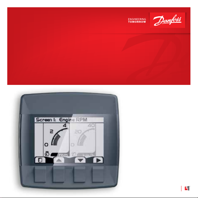
The Engine Information Center (EIC)
The DP2xx Series Graphical Terminal comes installed with the powerful and
exible Danfoss Engine Information Center (EIC) J1939 engine monitor
software application. Use the application to customize the look and feel of
your individual engine monitoring needs by creating and controlling analog
and digital display information in the screen congurations that work best for
your performance requirements.
Navigate through diagnostic information and conguration screens with ease
by using the four context-dependent soft keys located at the front of the
display. Choose from 50 dierent monitoring parameter proles to customize
the DP2xx terminal.
Up to four signals can be monitored on each screen. Use the Engine
Information Center software to congure the DP2xx for alarms and alerts.
511032748_Rev DA_Sep2014
User Manual EIC-Engine Information Center – DP2xx
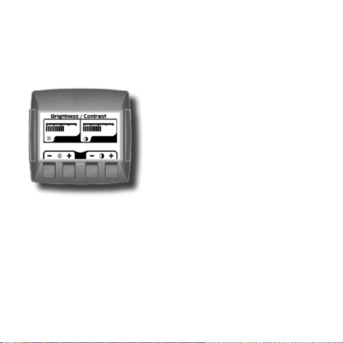
Brightness/Contrast Adjustment
Adjust brightness and contrast levels by
pressing soft key 2. This will display the
brightness and contrast soft key bar.
The bar will disappear after 3 seconds of
inactivity.
Navigation Using Soft Keys
The DP2xx Series Graphical Terminal is controlled by navigation through a set
of four soft keys located at the lower front of the display. The keys are context
dependent. Soft key selection options are displayed above each key and are
dependent on the current navigation location within the engine monitor
software program. As a general rule, the far right soft key is the selector
button and the far left soft key is the step back one screen key. To optimize full
screen use, the on-screen selections are not displayed when not in use. Press
any soft key to display current selection options. The selection options will be
displayed for three seconds.
6 11032748_Rev DA_Sep2014
User Manual EIC-Engine Information Center – DP2xx
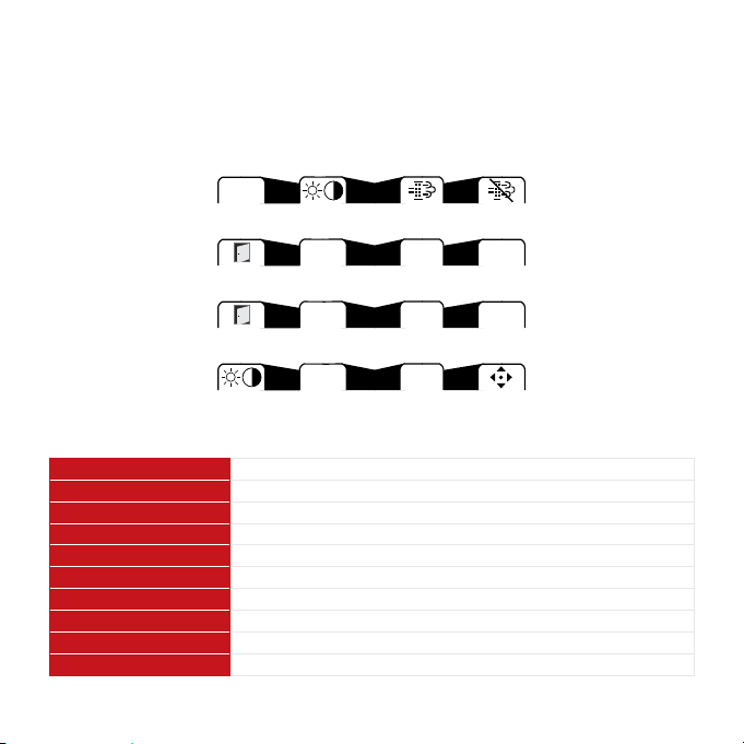
Navigation Using Soft Keys
Next Brightness/ Initiate Inhibit
Menu Contrast Switch Switch
Exit/Back Navigate Navigate Select
One Screen Up Down
Exit/Back Navigate Navigate Next
One Screen Up Down
Brightness/ Navigate Navigate Next
Contrast Up Down
Screen Navigation
Brightness/Contrast Press to access brightness and contrast settings
Navigate Up Press up to move up through menu items or screens
Navigate Down Press up to move down through menu items or screens
Main Menu Press to go to Main Menu screen
Exit/Back one screen Press to go back one screen
Select Press to accept selection
Next Press to select next digit or screen element
Initiate Switch Press to force regeneration of particulate lter
Inhibit Switch Press to inhibit particulate lter regeneration
Previous Press to navigate to previous menu
711032748_Rev DA_Sep2014

User Manual EIC-Engine Information Center – DP2xx
EIC DP2xx Force and Inhibit Regeneration software function description
While the unit is displaying one of the Monitor Screens, pressing any soft key
will show the available Navigation actions in an action menu. There are two
separate action menus on this level; the rst one to appear contains the
following actions (from left to right):
y Next Menu
y Screen Brightness/Contrast
y Initiate Switch (Force Regeneration)
y Inhibit Switch (Inhibit Regeneration)
Selecting ‘Next Menu’ will display the second action menu with actions
unrelated to the function described herein. Pressing it again will show the
rst set of actions once more. If no soft keys are pressed and released for
2.5 seconds while the action menu is shown the menu will disappear and the
actions are no longer available. Pressing (and releasing) any soft key will
activate the rst menu once more.
8 11032748_Rev DA_Sep2014

User Manual EIC-Engine Information Center – DP2xx
y Force Regeneration action
If the user selects the Force Regeneration action while the action menu is
being displayed; bit 2 (out of 0-7) in byte 5 (out of 0-7) will be set to 1 (true)
in the J1939 message PGN 57344 bound for the engine. This change
prompts the message to be transmitted. The bit will stay like this for the
duration of the soft key press or for the 2.5 second countdown to soft key
inactivity, whichever occurs rst. The bit is then reset to 0 (false).
The soft key press also prompts the display to show a popup lasting for
5 seconds. This popup simply says “Regeneration Forced”. If the display
does not receive an acknowledgement from the engine on the change to
message PGN 57344 the last half of the popup will say “No Engine Signal”.
This acknowledgement is the command that lights up the Forced
Regeneration LED on the display unit housing.
y Inhibit Regeneration action
If the user instead selects the Inhibit Regeneration action while the action
menu is being displayed the same function as described above will be
executed, with some dierences;
– Bit 0 (out of 0-7) in byte 5 (out of 0-7) is set to 1 (true) instead.
– The popup says “Regeneration Inhibit” instead.
– The acknowledgement lights up the Regeneration Inhibit LED instead.
911032748_Rev DA_Sep2014
User Manual EIC-Engine Information Center – DP2xx
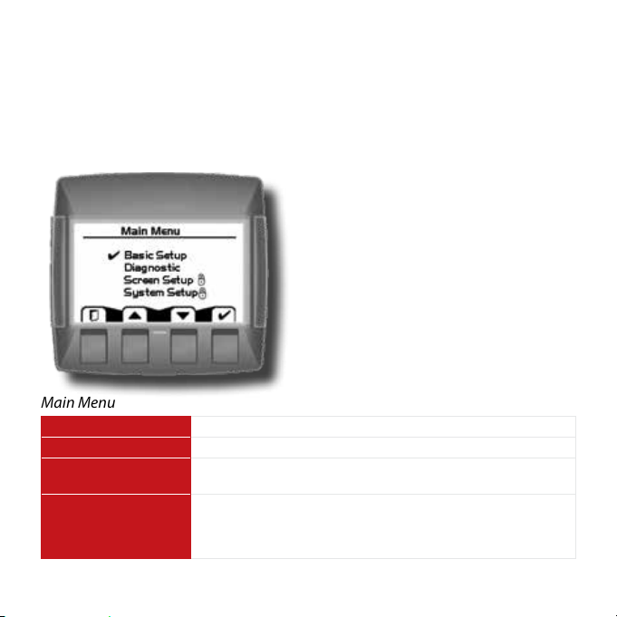
Main Menu
Start Menu
Start Menu – Main Menu
The Main Menu screen is the starting
point for conguring the DP2xx Series
Graphical Terminal.
Main Menu
Basic Setup Use to set Time/Date, Language and Units
Diagnostics Use to set System Info, access Fault Log and J1939 lists.
Screen Setup Use to set Parameters, choose number of screens and select
System Setup Use to reset trip and default settings,
10 11032748_Rev DA_Sep2014
screen. (PIN protected)
access CAN information,
select display settings and set PIN information.
(PIN protected)
User Manual EIC-Engine Information Center – DP2xx
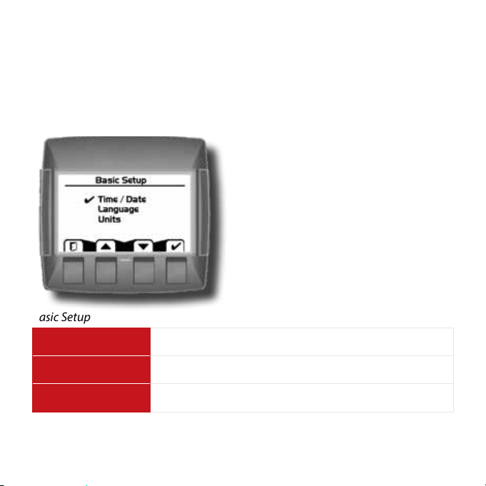
Main Menu
Basic Setup
Overview
Use the Basic setup screen to set time,
language and display units for the
DP2xx series terminal.
Basic Setup
Time/Date Use Time/Date to set, date and display style for time and date
information.
Language Use Language to set the system language. The default
language is English.
Units Use Units to set speed, distance, pressure, volume,
temperature, fuel rate and economy settings.
1111032748_Rev DA_Sep2014
User Manual EIC-Engine Information Center – DP2xx
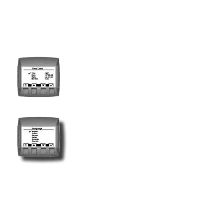
Main Menu
Basic Setup
Time/Date
Use Time/Date screen to set Time, Date, calendar
style and time style. Use up, down select and next
soft keys to navigate.
Language
Use Language screen to select program language.
Languages available, English, French, German,
Italian, Swedish and Spanish.
The default language setting is English.
12 11032748_Rev DA_Sep2014
User Manual EIC-Engine Information Center – DP2xx
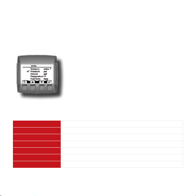
Main Menu
Basic Setup
Units
Use the up, down, select and next soft keys to
dene unit measurements.
Unit Selection Options
Speed km/h, mph
Distance km, mi
Pressure kPa, bar, lbs/sq in
Volume l, gal, imp gal
Temperature °C, °F
Fuel Economy 1/100 km, mpg, mpig
Fuel Rate l/h, g/h, ig/h
1311032748_Rev DA_Sep2014
User Manual EIC-Engine Information Center – DP2xx
Main Menu
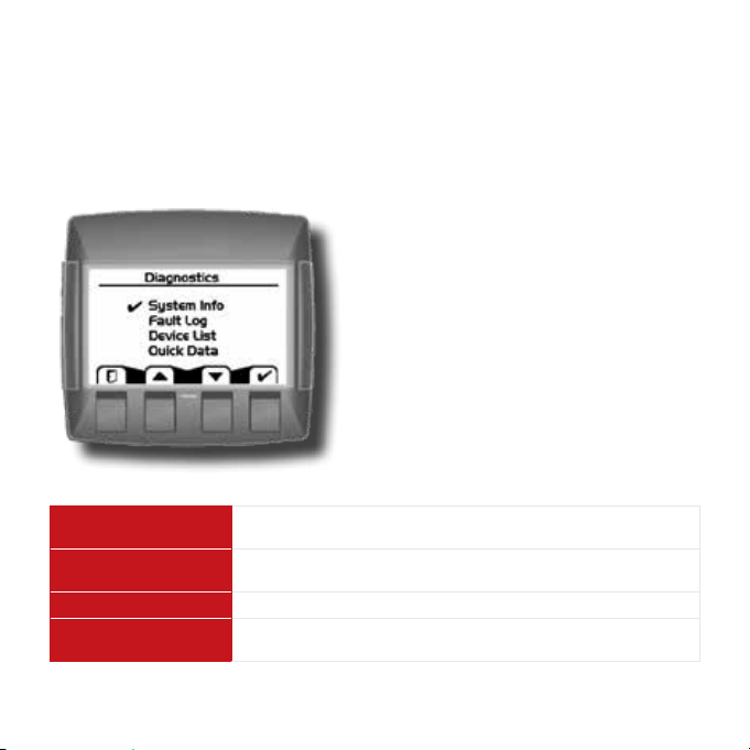
Diagnostics
Overview
Use the Diagnostics screen to display
current system information, view and
monitor fault logs and display all J1939
devices connected to the graphical
terminal.
Diagnostics
System Info Selecting System Info will display hardware, software, system
Fault Log Use Fault Log to view and monitor current and previous fault
Device List The Device List will list all currently connected J1939 devices.
Quick Data Use Quick Data to set up a customized signal list that can be
14 11032748_Rev DA_Sep2014
and node information for connected devices.
information.
quickly scrolled through in one signal per page format.
User Manual EIC-Engine Information Center – DP2xx
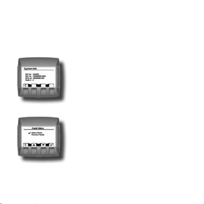
Main Menu
Diagnostics
System Info
The system info screen displays the hardware
system serial number, current software version,
current system version and node number. Only
information is displayed in the System Info
window. No changes can be made.
Fault Log
Fault information is saved and stored to the fault
log. Select either Active or Previous Faults to
monitor fault activity. Select specic faults to list
more information.
1511032748_Rev DA_Sep2014

User Manual EIC-Engine Information Center – DP2xx
Main Menu
Diagnostics
Fault Log: Active and Previous Faults
Selecting Active Faults in the Fault Menu will
display all active faults on the CAN network.
Selecting Previous Faults in the Fault Menu will
display all previously active faults on the CAN
network.
16 11032748_Rev DA_Sep2014

User Manual EIC-Engine Information Center – DP2xx
Main Menu
Diagnostics
Fault Pop-Up Alarms
When a fault is detected on the CAN network, a
ashing red warning alarm will be activated and a
fault information pop-up window will be displayed
listing current fault information.
Warning lights will ash when a pop-up alarm
occurs and will stay ashing until acknowledged.
Warning lights will remain lit until the fault is no
longer on the CAN network.
Fault pop-up soft key actions
Select to clear pop-up and return directly to previous display
information
▼
▲
✔
Select to go to next fault information
Select to go to previous pop- up information
Select to clear pop-up and go to the current active fault
complete information screen
1711032748_Rev DA_Sep2014

User Manual EIC-Engine Information Center – DP2xx
Main Menu
Diagnostics
Fault Pop-Up Alarms
y Faults that have been acknowledged and are no longer active will be
shown in the Currently Active Faults log in italics.
y Faults no longer active will also be displayed in the Previous Faults log.
y Pop-up fault alarms can be disabled by setting the Fault Pop-Up to o in
the CAN section of the System Setup menu.
18 11032748_Rev DA_Sep2014

User Manual EIC-Engine Information Center – DP2xx
Main Menu
Diagnostics
Device List
The Device List page will list all J1939 devices and
addresses that are currently being monitored on
the network.
1911032748_Rev DA_Sep2014

User Manual EIC-Engine Information Center – DP2xx
Main Menu
Diagnostics
Quick Data
The Quick Data function allows selected signals to
be monitored in a scrollable single view display.
To select signals for display, press the far right soft
key.
Quick Data softkey
Scroll through signal list using the up and down
arrow soft keys and select/deselect signals for
Quick View monitoring by pressing the far right
(check mark) soft key. Signals selected for display
will show an asterisks to the left of the signal
name.
20 11032748_Rev DA_Sep2014

User Manual EIC-Engine Information Center – DP2xx
Main Menu
Screen Setup
Overview
Use Screen Setup to enter parameter
settings, select number of signal screens
and select individual screens for setup.
Screen Setup
Parameters Set Parameters for RPM, Speed, Fuel, Wheel and Pulse/
Revolutions information.
Number of Screens Select Number of Screens for information display. Select
from 1 to 4 screens for display.
Select Screen Use to Select Screen to set up signal information. Number of
screens available are dependent on number of screens
selected.
2111032748_Rev DA_Sep2014

User Manual EIC-Engine Information Center – DP2xx
Main Menu
Screen Setup
Parameters
Dene system parameter ranges for revolutions
per minute, speed, fuel, wheel diameter and
pulses per revolution display settings.
Number of Screens
Select number of screens for display. Choose from
1 to 4 screens. See page 22 for detailed screen set
up tutorial.
Select Screen
Select screen to customize. See page 27 for
detailed screen setup tutorial.
22 11032748_Rev DA_Sep2014

User Manual EIC-Engine Information Center – DP2xx
Main Menu
System Setup
Overview
Use System Setup to monitor and
control application systems. Reset to
default settings, make CAN selections,
control display settings, set PIN
congurations and reset trip functions.
System Setup
Reset Defaults Select to reset all system information to the default settings
status.
CAN Select to customize CAN settings.
Display Select to customize display settings.
PIN Setup Use to set custom PIN settings.
Trip Reset Select to reset all trip information.
2311032748_Rev DA_Sep2014

User Manual EIC-Engine Information Center – DP2xx
Main Menu
System Setup
Reset Defaults
Select Reset Defaults to reset all EIC settings to
original factory default settings.
CAN Settings
Use the CAN settings selection to make the
following selections:
CAN Settings
Engine Address Select engine address. Selection range is 0–253.
CAN Select 1, 2 or 3 to determine how to interpret non-standard
Fault Popup Select on or o to enable or disable on screen popup
24 11032748_Rev DA_Sep2014
fault messages. Consult engine manufacturer for correct
setting.
messages.
User Manual EIC-Engine Information Center – DP2xx
Main Menu
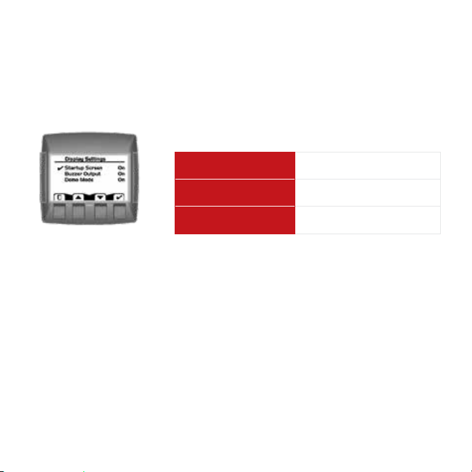
System Setup
Display Setting
Startup Screen Select to enable/disable logo
display at startup
Buzzer Output Select to enable/disable
warning buzzer functionality.
Demo Mode Select on/o to enable
demonstration mode.
2511032748_Rev DA_Sep2014

User Manual EIC-Engine Information Center – DP2xx
Main Menu
PIN Protection
Change PIN Code
To reduce the potential for errors, Screen Setup
and System Setup menu options can only be
accessed after entering a PIN code. The default
code is 1-2-3-4. The PIN number can be changed
by using PIN Setup located in the System Setup
menu.
Trip Reset
Select Yes to reset all trip data.
26 11032748_Rev DA_Sep2014

User Manual EIC-Engine Information Center – DP2xx
Setup Options
Selecting Screen Number and Types
1. Select from one to four screens for
signal monitoring.
Navigate to Main Menu>Screen
Setup>Number of Screens.
2. Select screen type for each of the
screens selected.
Navigate to Main Menu>Screen
Setup>Select Screen.
Choose from three types of screen
setups. Select screen type and press the
far right soft key (check mark) to go to
signal monitoring options.
2711032748_Rev DA_Sep2014

User Manual EIC-Engine Information Center – DP2xx
Setup Options
Screen Variants
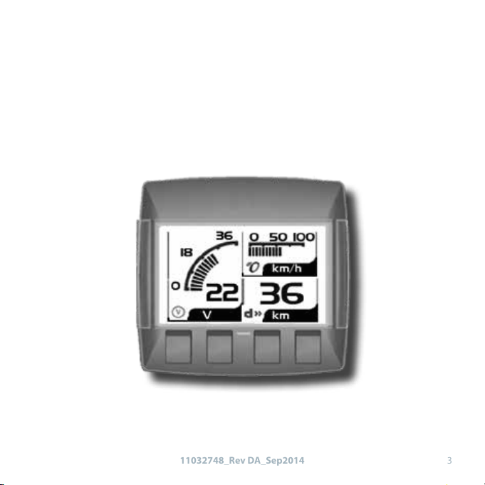
Screen Type 1
Type 1 is a two-up screen view with
two signal capacity.
Screen Type 2
Type 2 is a three-up screen view with
one large and two small signal
display capacities.
Screen Type 3
Type 3 is a four-up display with four
small signal display capacity.
28 11032748_Rev DA_Sep2014

User Manual EIC-Engine Information Center – DP2xx
Setup Options
Selecting J1939 Monitor Signals
3. After screen type selection, select
signals to monitor. Use the up and down
arrow soft keys to cycle through
available signal selections.
4. After making a signal selection, press
the right arrow (Next) soft key to go to
the next selection area. Use the up,
down arrow, next and select soft keys to
select signal. Select the right arrow soft
key to move to the next selection area.
2911032748_Rev DA_Sep2014

User Manual EIC-Engine Information Center – DP2xx
Setup Options
Selecting J1939 Monitor Signals
5. Using the right arrow soft key will
rotate through the selections in a
clockwise rotation.
When nished with all screen signal
selections press the exit (door symbol)
soft key to return to previous menus.
6. Navigate back for more screen
selections or press the Exit soft key 5
times to display current selections.
30 11032748_Rev DA_Sep2014

User Manual EIC-Engine Information Center – DP2xx
J1939 Monitor Controls
The following tables list the J1939 engine and transmission parameters that
are available and can be monitored in the DP2xx Graphical Terminal.
For more information on setting up monitor controls in using the Engine
Information Center, please refer to Selecting J1939 Signals on page 29.
3111032748_Rev DA_Sep2014

User Manual EIC-Engine Information Center – DP2xx
J1939 Monitor Controls
Symbols
Signal monitor functions
Symbol Name/Function Units
Actual Engine Torque %
Engine Air Inlet Temperature Pa × 1000
Engine Coolant Level %
Engine Coolant Pressure Pa × 1000
Engine Coolant Temperature °C
Engine Exhaust Gas Temperature °C
Engine Hours Hours
Engine Intake Manifold Temperature °C
Engine Oil Level Max = 100, min = 0
Engine Oil Pressure Pa × 1000
Engine Oil Temperature °C
Engine RPM RPM
Engine Turbocharger Boost Pressure Pa × 1000
Fuel Level %
Wheel-based Vehicle Speed kph/mph
32 11032748_Rev DA_Sep2014

User Manual EIC-Engine Information Center – DP2xx
Symbol Name/Function Units
Accelerator Pedal Position %
Alternator Current Amp
Alternator Voltage Volts
Auxiliary Temperature °C
Average Fuel Economy km/l
Trip Average Fuel Rate l/h
Barometric Pressure Pa × 1000
Current Gear N/A
Distance Remaining Undened
Engine Air Filter Dierential Pressure Pa × 1000
Engine Air Inlet Temperature °C
Engine Injector Metering Rail 1 Pressure MPa
Engine Injector Metering Rail 2 Pressure MPa
Engine Intercooler Temperature °C
Engine Turbocharger Oil Temperature °C
Fan Speed %
Engine Fuel Delivery Pressure Pa × 1000
Fuel Rate l/h
3311032748_Rev DA_Sep2014

User Manual EIC-Engine Information Center – DP2xx
Symbol Name/Function Units
Fuel Remaining %
Engine Fuel Temperature 1 °C
Instantaneous Fuel Economy km/l
Internal Voltage Volts
Net Battery Current Amps
Selected Gear N/A
Torque Convertor Lock-up Engaged Conditional
Total Distance Variable
Engine Total Fuel Used Variable
Transmission Input Shaft Speed RPM
Transmission Oil Pressure Pa × 1000
Transmission Oil Temperature °C
Transmission Output Shaft Speed RPM
Trip Distance km
Trip Engine Hours hrs
Trip Fue l l
% Soot Soot level percent %
% Ash Ash level percent %
34 11032748_Rev DA_Sep2014

User Manual EIC-Engine Information Center – DP2xx
LED Indicators
Lamps
Particulate Filter Lamp
Stage 1 The right Amber LED indicates the initial need for regeneration.
The lamp is on solid.
Stage 2 The right Amber LED indicates an urgent regeneration.
Lamp ashes with 1 Hz.
Stage 3 Same as Stage 2 but check engine lamp will also turn on.
High Exhaust System Temperature Lamp
The left Amber LED indicates the increase of exhaust system temperature due
to regeneration.
Regeneration Disabled Lamp
The left Amber LED indicates that the regeneration disabled switch is active.
3511032748_Rev DA_Sep2014

User Manual EIC-Engine Information Center – DP2xx
Installation/Mounting Instructions
Panel Bracket Assembly
Mounting and fastening Installation
y Fastening hole depth: 11 mm
y May be threaded M3/ST3 and used with standard
screws. Reassembly with self-tapping screws may
damage existing threads in housing.
y Maximum torque: 0.9 Nm.
36 11032748_Rev DA_Sep2014
W Caution:
Excessive screw
torque force may
cause damage to
housing.

User Manual EIC-Engine Information Center – DP2xx
Mounting screws
DP2xx - M3×10 screw (×4) - 10107464
DP250 - ST3×12 screw (×4) - 11089413
Panel mounting bracket
DP2xx - 10105917
DP250 - 11072811
Panel gasket seal
DP200 -10107631
DP211 - 10107355
DP250 - 11075186
Installation/Mounting Instructions
Surface Mount
3711032748_Rev DA_Sep2014

User Manual EIC-Engine Information Center – DP2xx
105.5 mm [4.15 in] (±0.7 mm[0.027 in])
100.5 mm [3.95 in] (±0.7 mm [0.27 in])
Installation/Mounting Instructions
Panel Gasket Dimensions
y Gasket seal area crosshatched
y Panel thickness: 2-5 mm
y Interior edges chamfered 0.2- 0.5 mm
38 11032748_Rev DA_Sep2014

User Manual EIC-Engine Information Center – DP2xx
DP200 Series Model Code Variants
A
Model Name
DP200 Graphic al Display, IP 67 above pan el
B
Inputs/Outputs
00 1 CAN por t, 2 DIN/AIN
01 1 C AN port, 6 DIN/AIN
04 2 CAN por ts, 2 DIN/AIN
C
Real Time Clock / Low Temperature Functionality
00 No RTC, fu ll LTF
01 R TC and LTF
D
Flash Memory/Application Key
02 2MB wi thout Applicati on Key
03 2MB with Application Key
E
Application Log
00 None
04 4 MB
F
USB Port Type
00 None
01 USB Dev ice
3911032748_Rev DA_Sep2014

User Manual EIC-Engine Information Center – DP2xx
DP211 Series Model Code Variants
A
Model Name
DP 211 Graphic al Display with inte grated USB port
B
Inputs/Outputs
04 2 CAN por ts, 2 multifun ction
C
Real Time Clock / Low Temperature Functionality
01 R TC and LTF
D
Flash Memory/Application Key
02 2MB wi thout Applicati on Key
03 2MB with Application Key
E
Application Log
04 2 MB
F
USB Port Type
01 USB Dev ice
40 11032748_Rev DA_Sep2014

User Manual EIC-Engine Information Center – DP2xx
DP250 Series Model Code Variants
Model Name
DP250
Inputs/Outputs (All models have 2 multifunction
00 1 CAN port
01 1 CAN p ort, 4 DIN/AIN
04 2 CAN port s
05 User Congurable
06 User Congurable:
Real Time Clock / Low Temperature Functionality
00 No RTC and LTF
01 RTC an d LTF
Flash Memory/Application Key
04
05
Application Log
00 None
05 16 MB
USB Port Type
00 None
01
02
Color Graphical Display
2 CAN, 2 DIN /AIN or
1 CAN por t, 4 DIN/AIN
1 RedCA N port, 1 CAN por t or
1 RedCA N port, 2 DIN/AIN
16 MB without A pplication Key
16 MB with Appli cation Key
USB Device i n front
USB Device i n rear
4111032748_Rev DA_Sep2014

User Manual EIC-Engine Information Center – DP2xx
1
6
7
12
Connection/Pinout settings
DP200 Series- Deutsch Connector
DP200 Series pin assignments
Code B 00 Code B 01 Code B 04
1 Power ground–
2 Power supply+
3 CAN 0+
4 CAN 0–
5 AIN/ CAN Shield
6 See Code B option N/C DIN/AIN N/C
7 See Code B option N/C DIN/AIN N/C
8 See Code B option N/C DIN/AIN C AN 1+
9 See Code B option N/C DIN/AIN CAN 1–
10 DIN/AIN/FREQ IN/CURRENT IN
11 DIN/AIN/FREQ IN/CURRENT IN
12 DOUT (0.5A)
42 11032748_Rev DA_Sep2014

User Manual EIC-Engine Information Center – DP2xx
1
6
7
12
Connection/Pinout settings
DP250 Series- Deutsch Connector
DP250 Series pin assignments
1 Power ground-
2 Power supply+
3 CAN 0+
4 CAN 0–
5 AIN/ CAN Shield
6 See Code B option/TI
7 See Code B option/TI
8 See Code B option/TI
9 See Code B option/TI
10 DIN/AIN/FREQ IN/CURRENT IN, RHEOSTAT
11 DIN/AIN/FREQ IN/CURRENT IN, RHEOSTAT
12 DOUT (0.5A)
4311032748_Rev DA_Sep2014

User Manual EIC-Engine Information Center – DP2xx
Connection/Pinout settings
Related Parts & Kits
DP200 Series Related Products Part Numbers
10100944 Deutsch Mating Connector Bag Assembly (20-24 AWG)
10102025 Deutsch Mating Connector Bag Assembly (16-20 AWG)
Electrical Connection Kits
10100944 12-pin Deutsch connection Kit
Contents:
10100738 DTM06-12SA 12-pin Deutsch connec tor
10100743 Deutsch terminal
10100741 WM 12S locking plug
Connection Tools
1010074 4 Deutsch stamped contacts terminal crimp tool, size 20
10100745 Deutsch solid contacts terminal crimp tool
44 11032748_Rev DA_Sep2014

User Manual EIC-Engine Information Center – DP2xx
Connection/Pinout settings
Related Parts & Kits (Continued)
DP200 Mounting Kit
1010735 4 DP200 Series Mounting Hardware Kit
Contents:
10107464 Mounting screws (×4), M3 × 10
10107631 Panel gasket seal
10105917 Panel mounting bracket
DP211 Mounting Kit
10107264 DP211 Series Mounting Hardware Kit
Contents:
10107464 Mounting screws (×4), M3 × 10
10107355 Panel gasket seal
10105917 Panel mounting bracket
DP250 Mounting Kit
11079236 DP250 Series Mounting Hardware Kit
Contents:
11089413 Mounting screws (×4), ST3 × 12
11075786 Panel gasket seal
11072811 Panel mounting bracket
4511032748_Rev DA_Sep2014

User Manual EIC-Engine Information Center – DP2xx
Connection/Pinout settings
Related Parts & Kits (Continued)
Software
10101000 PLUS+1 GUIDE Software Application ( including Service Tool and
46 11032748_Rev DA_Sep2014
Screen Editor)

User Manual EIC-Engine Information Center – DP2xx
W Important Safety Information
y Disconnect your machine’s battery power before connecting power and signal cables to
the DP2xx.
y Before doing any electrical welding on your machine, disconnec t all power and signal
cable cables connected to the DP2x x.
y Do not exceed the DP2xx power supply voltage ratings. Using higher voltages may
damage the DP2xx and can create a re or electrical shock hazard.
y Do not use or store the DP2xx where ammable gases or chemicals are present.
y Using or storing the DP2xx where ammable gases or chemicals are present may cause an
explosion.
y Software congures the keypad buttons on the DP2xx. Do not use these buttons to
implement critical safety features. Use separate mechanical switches to implement critical
safety features such as emergency stops.
y Design systems that use the DP2xx so that a communication error or failure between the
DP2xx and other units cannot cause a malfunction that might injure people or damage
material.
y The protective glass over the DP2xx display screen will break if hit with a hard or heavy
object. Install the DP2xx to reduce the possibility of it being hit by hard or heavy objects.
y If you break the protective glass of the DP2xx screen, remove the DP2xx and immediately
return it to Danfoss for service.
y Storing or operating a DP2x x in an environment that exceeds the DP2xx specied
temperature or humidity rating may damage the DP2xx.
y Always clean the DP2xx with a soft, damp cloth. Use a mild dishwashing detergent as
needed.
y The DP2xx is not user serviceable. Return the DP2xx to the factory in case of failure.
4711032748_Rev DA_Sep2014

Comatrol
www.comatrol.com
Schwarzmüller-Inverter
www.schwarzmueller-
inverter.com
Turolla
www.turollaocg.com
Danfoss Power Solutio ns is a global manufacturer and supplier of high-qu ality hydraulic and
electronic components. We spe cialize in providing state-of-the-art techno logy and solutions that
excel in the harsh operating conditions of the mobil e o -highway market. Build ing on our extensive
applications expertise, we work cl osely with our customers to ensure exceptional performance for a
broad range of o -highway vehicles.
We help OEMs around the world speed up system d evelopment, reduce costs and bring vehicles to
market faster.
Danfoss – Your Strongest Partner in Mobile Hydraulics.
Go to www.powersolutions.danfoss.com for further product information.
Wherever o -highway vehicles are at work, so is Danfoss.
We o er expert worldwide support for our c ustomers, ensuring the best possible solutions for
outstanding perfo rmance. And with an extensive network of Global Ser vice Partners, we also provide
comprehensive global service for all of o ur components.
Please contact the Danfoss Power Solutions representative ne arest you.
Products we o er:
Bent A xis Motors
Close d Circuit Axial Piston
Pumps and Motors
Di splays
Elec trohydraulic Power
Steering
Elec trohydraulics
Hydraulic Power Steering
Inte grated Systems
Joysti cks and Control
Handles
Micro controllers and
Software
Op en Circuit Axial Piston
Pumps
Orbital Motors
P LUS +1® GUIDE
Propor tional Valves
Sensors
Steering
Transit Mixer Drives
Local address:
Products we o er:
Bent A xis Motors
Close d Circuit Axial Piston
Pumps and Motors
Di splays
Elec trohydraulic Power
Steering
Elec trohydraulics
Hydraulic Power Steering
Inte grated Systems
Joysti cks and Control
Handles
Micro controllers and
Software
Op en Circuit Axial Piston
Pumps
Orbital Motors
P LUS +1® GUIDE
Propor tional Valves
Sensors
Steering
Transit Mixer Drives
Danfoss
Power Solutions (US) Company
2800 East 13th Street
Ames, IA 50010, USA
Phone: +1 515 239 6000
Danfoss can accept no responsibility for possible errors in catalogues, brochures and other printed material. Danfoss reserves the right to alter its products without notice. This also applies to products
already on order provided that such alterations can be made without changes being necessary in specifications already agreed.
All trademarks in this material are property of the respective companies. Danfoss and the Danfoss logotype are trademarks of Danfoss A/S. All rights reserved.
Danfoss Power Solutio ns is a global manufacturer and supplier of high-qu ality hydraulic and
electronic components. We spe cialize in providing state-of-the-art techno logy and solutions that
excel in the harsh operating conditions of the mobil e o -highway market. Build ing on our extensive
applications expertise, we work cl osely with our customers to ensure exceptional performance for a
broad range of o -highway vehicles.
We help OEMs around the world speed up system d evelopment, reduce costs and bring vehicles to
market faster.
Danfoss – Your Strongest Partner in Mobile Hydraulics.
Go to www.powersolutions.danfoss.com for further product information.
Wherever o -highway vehicles are at work, so is Danfoss.
We o er expert worldwide support for our c ustomers, ensuring the best possible solutions for
outstanding perfo rmance. And with an extensive network of Global Ser vice Partners, we also provide
comprehensive global service for all of o ur components.
Please contact the Danfoss Power Solutions representative ne arest you.
Valmova
www.valmova.com
Hydro-Gear
www.hydro-gear.com
Daikin-Sauer-Danfoss
www.daikin-sauer-danfoss.com
Danfoss
Power Solutions GmbH & Co. OHG
Krokamp 35
D-24539 Neumünster, Germany
Phone: +49 4321 871 0
Comatrol
www.comatrol.com
Schwarzmüller-Inverter
www.schwarzmuellerinverter.com
Turolla
www.turollaocg.com
Danfoss
Power Solutions ApS
Nordborgvej 81
DK-6430 Nordborg, Denmark
Phone: +45 7488 2222
Danfoss
Power Solutions Trading
(Shanghai) Co., Ltd.
Building #22, No. 1000 Jin Hai Rd
Jin Qiao, Pudong New District
Shanghai, China 201206
Phone: +86 21 3418 5200
11032748_Rev DA_Sep2014 www.danfoss.com © Danfoss A/S
 Loading...