

Page 1

Data Sheet
PLUS+1® Mobile Machine Displays
DP250 Series
Durable color display
Danfoss DP250 Series Displays are elements of the
PLUS+1® family of mobile machine management
products.
The DP250 series provide mobile machine OEMs with
a range of rugged, high quality, cost effective color
displays.
DP250 Series variants include several Input options,
dual CAN port options and two USB options: a USB
device mini-connector on the front of the display or a
USB connector on the rear of the display.
Large function-programmable buttons provide tactile
feedback. The high resolution color display is
viewable in a wide range of lighting conditions.
Backlight and contrast settings are programmable.
The DP250 display family features robust mechanical,
electrical and environmental specifications that meet
the harsh operating conditions found in mobile
machine applications.
Features
•
User-programmable with PLUS+1
GUIDE (Graphical User Integrated
Development Environment)
•
J1939 engine monitor (Engine
Information Center) application
software available (application keyed)
•
High resolution color TFT display
(240x320 pixels, 15-bit color)
•
6 software controlled LEDs (2 red, 2
amber, 2 green)
•
4 user-programmable soft keys
•
2 CAN 2.0 ports option
•
4 digital analog inputs options
•
All models include 2 multifunction
inputs (DIN/AIN/FrequencyIN/
CurrentIN, 4–20 mA)
•
1 fixed-range analog input/CAN shield
pin
®
•
16 MB program memory
•
16 MB application log memory option
•
Real-time clock
•
Buzzer output
•
Two USB options:
‒
‒
•
IP 67 ingress rating
‒
•
-30°C to 70°C (-22°F to 158°F) operating
temperature range
•
CE marked
Comprehensive technical literature online
at powersolutions.danfoss.com
Mini USB connector (USB device
function) on the front of the display
Binder USB connector (USB function)
on the back of the display
Exception: IP 54 rating for DP250
display with front mini-USB
connector
©
Danfoss | Oct 2016 L1026137 | AI00000107en-US0503 | 1
Page 2

115.90 [4.56]
59.10 [2.33]
111.40 [4.39]
34.00 [1.33]
25.00 [0.98]
41.50 [1.63]
32.50 [1.27]
kwa1397051901505
104.00 [4.09]
99.00
[3.90]
P200197
1 52 43
P200 129
1
2
3
4
5
6
7
8
Data Sheet
Mobile Machine Displays DP250 Series
Dimensions
DP250 in mm[in]
Mounting panel cutout in mm[in]
Processor ARM 7 core, 16/32 bit/ 72 MHz
RAM 64KB on-chip, 1MB on board
FRAM 16 KB
Supply Voltage 9–63 Vdc/6.5W
Current
Heater 10W
Consumption
Connector DEUTSCH DTM-12
LCD Glass TFT with 15-bit resolution
Resolution 320 x 240 pixels
Viewable Area 70.08 mm x 52.56 mm [3.15 x 2.16]
IP Rating IP67 or IP54
Operation
Temperature
Storage
Code C00: –20 °C - +70°C [–4°F - +158°F]
Code C01: –30 °C - +70°C [–22°F - +158°F]
–40 °C to +85°C [–40°F to +176°F]
Temperature
Weight 250g [0.5lb]
Vibration/Shock 5g/ 50g
EMC/ESD 100V/m / 15kV
The DP250 front mini-USB model option
carries an IP54 ingress rating. The USB
cover/ plug must be in place for full IP54
protection. This model variant is
recommended for in-cab installation only.
Specifications
USB mini-B connector pin out information
1 Vbus
2 Data -
3 Data +
4 Device ID (NC)
5 Ground
For full IP67 ingress rating of rear USB
models, the cable or plug must be in place.
Binder Series 702 USB connector pin out
information
1 Vbus
2 Data -
3 Data +
4 N/C
5 Ground
6 N/C
7 N/C
8 N/C
2 | © Danfoss | Oct 2016 L1026137 | AI00000107en-US0503
Page 3
Data Sheet
Mobile Machine Displays DP250 Series
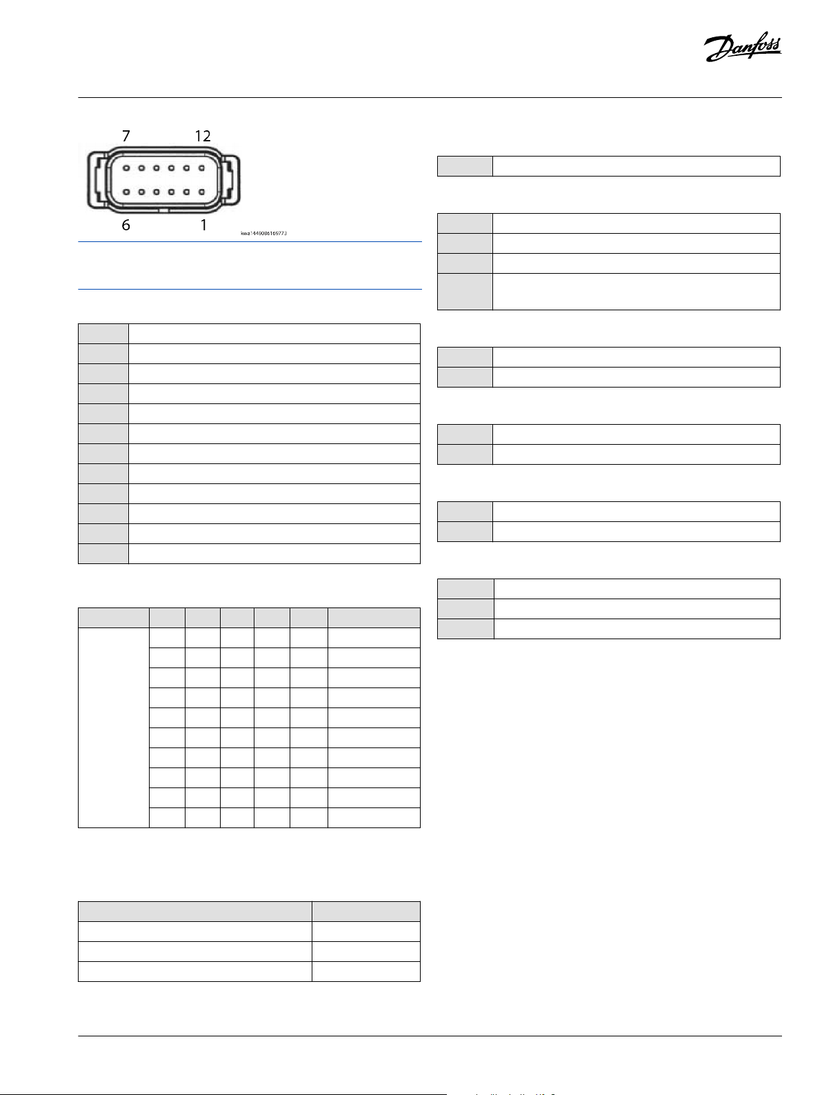
Use care when wiring mating connector. Diagrams show device
pins.
DEUTSCH 12-pin connector pin out information
1 Power ground -
2 Power supply +
3 CAN 0 +
4 CAN 0 -
5 AIN/ CAN Shield
6 See Code B option/TI
7 See Code B option/TI
8 See Code B option/TI
9 See Code B option/TI
10 DIN/AIN/FREQ IN/CURRENT IN, RHEOSTAT
11 DIN/AIN/FREQ IN/CURRENT IN, RHEOSTAT
12 DOUT (0.5A)
A: Model name
DP250 PLUS+1® Mobile Machine Displays
B: Inputs/Outputs (All models have 2 multifunction)
00 1 CAN port
01 1 CAN port, 4 DIN/AIN
05 User Configurable: 2 CAN, 2 DIN/AIN or 1 CAN, 4 DIN/AIN
06 User Configurable: 1 RedCAN port, 1 CAN port or 1 RedCAN
port, 2 DIN/AIN
C: Real Time Clock, low temperature functionality
00 No RTC and LTF
01 RTC and LTF
D: Flash Memory/Application Key
04 16MB without Application Key
05 16MB with Application Key
E: Application log
00 None
05 16MB
F: USB port type
Model features and Ordering information
A B C D E F Part number
DP250 00 00 04 00 00 11080686
00 01 05 00 00 11075899
01 01 04 05 00 11075900
01 01 05 05 00 11077442
05 01 04 05 00 11060814
05 01 05 05 00 11077443
06 01 04 05 01 11060816
06 01 05 05 01 11077444
01 01 05 05 02 11094414
01 01 04 05 02 11091448
1
EIC installed
2
With app key which allows EIC SW installation
Accessory information
Model Part number
DP2XX Panel Mounting Kit 11079236
DEUTSCH 12-pin Connector Kit (DTM06-12SA) 10100944
Binder Connector and Cable Kit (Series 702) 10103497
00 None
01 USB Device in front
02 USB Device in rear
1
2
2
2
2
©
Danfoss | Oct 2016 L1026137 | AI00000107en-US0503 | 3
Page 4

Danfoss can accept no responsibility for possible errors in catalogues, brochures and other printed material. Danfoss reserves the right to alter its products without notice. This also applies to products
already on order provided that such alterations can be made without changes being necessary in specifications already agreed.
All trademarks in this material are property of the respective companies. Danfoss and the Danfoss logotype are trademarks of Danfoss A/S. All rights reserved.
4 | © Danfoss | Oct 2016 L1026137 | AI00000107en-US0503
 Loading...