

Page 1
Introduction 1
1.
4.
3.
2.
5.
DOOR KEYPAD MOUNTING KIT - MOUNTING INSTRUCTIONS
1. INTRODUCTION
The Door Keypad is used for the same purpose as the standard control keypad. It is installed on the
door of a switchgear cabinet.
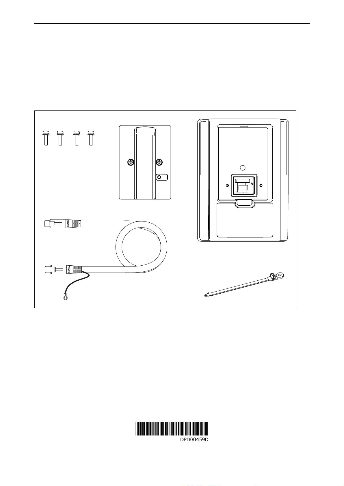
For the installation, you need the following parts (see picture below):
1. Door keypad base
2. Data cable with attached grounding cable
3. Screws (4 pcs)
4. Panel adapter kit (packaged); See manual in package for components
5. Cable tie
MAKE SURE THAT YOU HAVE RECEIVED ALL NECESSARY ITEMS!
Figure 1. Door keypad mounting kit
Document code: DPD00459D
Page 2
2 Mounting procedure
2. MOUNTING PROCEDURE
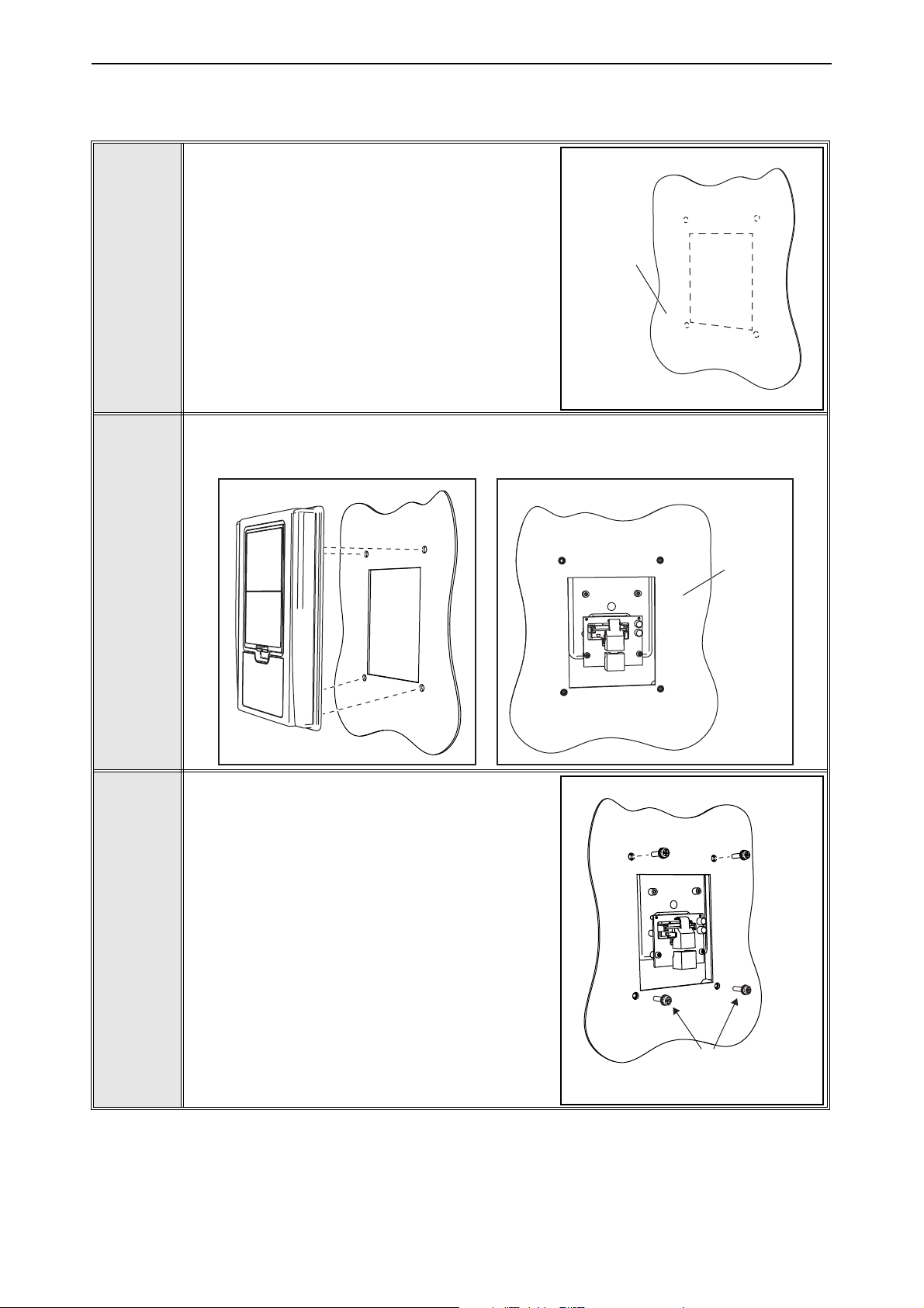
Make an opening in the cabinet door for the control keypad according to the dimensions in
Appendix 1.
Also make the holes in the cabinet door for the
screws using the dimensions in Appendix 1.
Cabinet
door
1
Place the control keypad base (1.) toward the opening so that the screw holes you
made in the cabinet door meet the bushings on the backside of the base.
Rear view
2
3
Cabinet
door
Fix the base on the cabinet door by tightening
the screws (3.).
Document code: DPD00459D
Leave two screws
still unfixed
Page 3
Mounting procedure 3
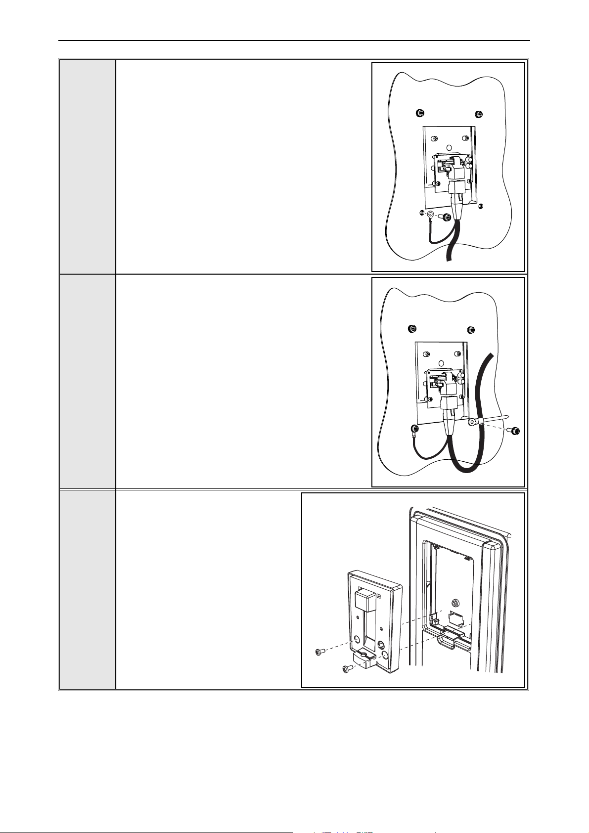
Fix the data cable grounding wire (2.) against the
backside of the cabinet door through one of the
screw holes.
NOTE: Ensure that a proper contact with the cabinet door is achieved. If necessary, remove the paint
from the metal surface.
Don't forget to place the washers (attached to the
screws) between the door and the screws. The
4
tightening torque to be applied is 1.5 Nm.
Connect the data cable (2.) to the terminal of the
keypad.
Fix the data cable (2.) against the backside of the
cabinet door through one of the screw holes. Use
the cable tie (5.) provided in the kit.
Don't forget to place the washers (attached to the
screws) between the door and the screws. The
tightening torque to be applied is 1.5 Nm.
5
6
Fix the transparent cover B of the
panel adapter kit (4.) to the keypad
base using the two screws provided
in the package. Tighten the screws
to max. 1 Nm.
Document code: DPD00459D
Page 4
4 Mounting procedure
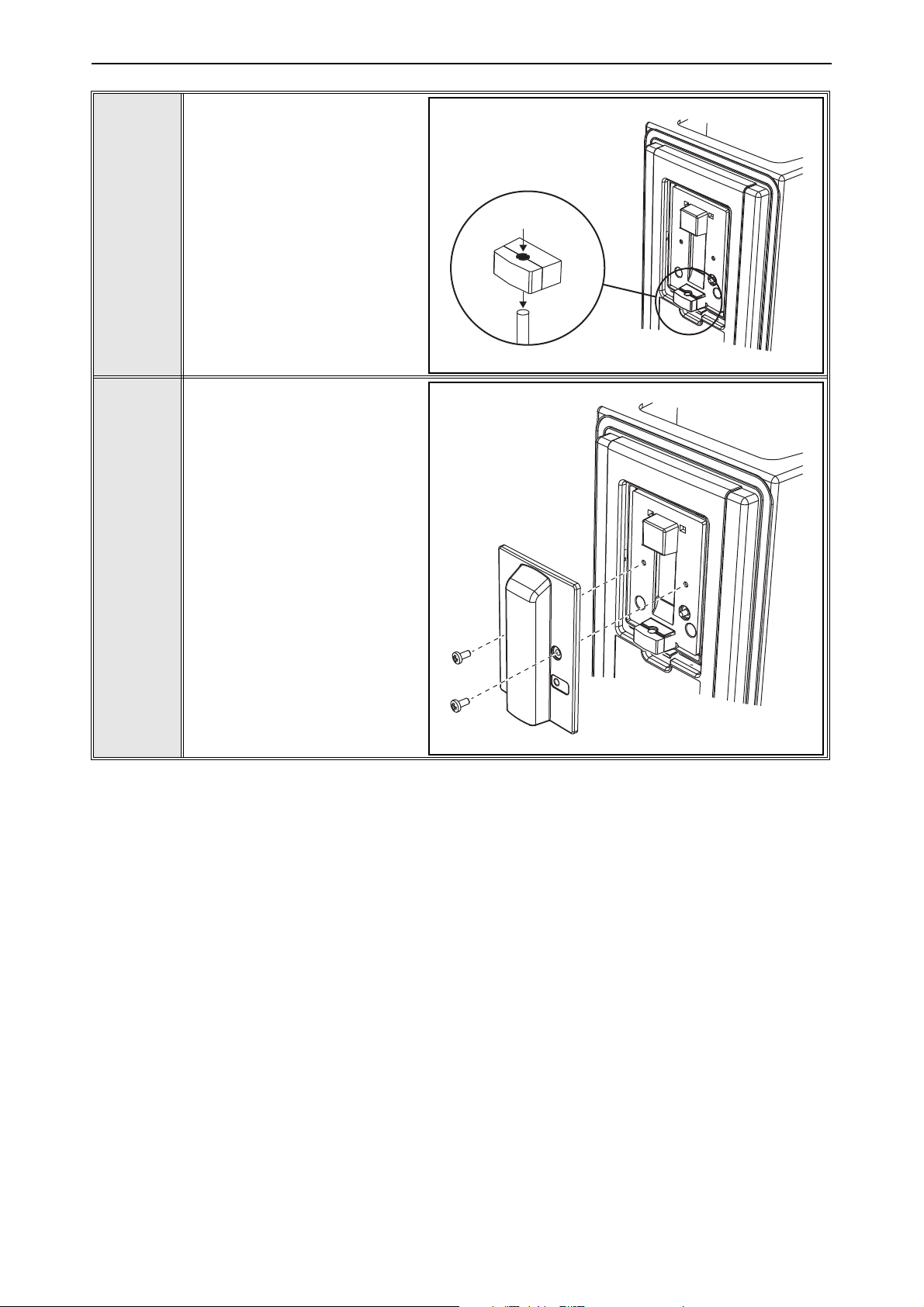
Detach the foam rubber gasket from the transparent cover
and punch out the cylinderformed piece of foam rubber in
order to open way for the
cable. The gasket can then be
split into two pieces.
7
Then insert the cable and fix
the black cover A of the panel
adapter kit (4.) with the two
screws provided. Tighten the
screws to max. 1 Nm.
8
Document code: DPD00459D
Page 5
APPENDIX 5
80
100
119
170
4
25
4 pcs Ø6
90
125
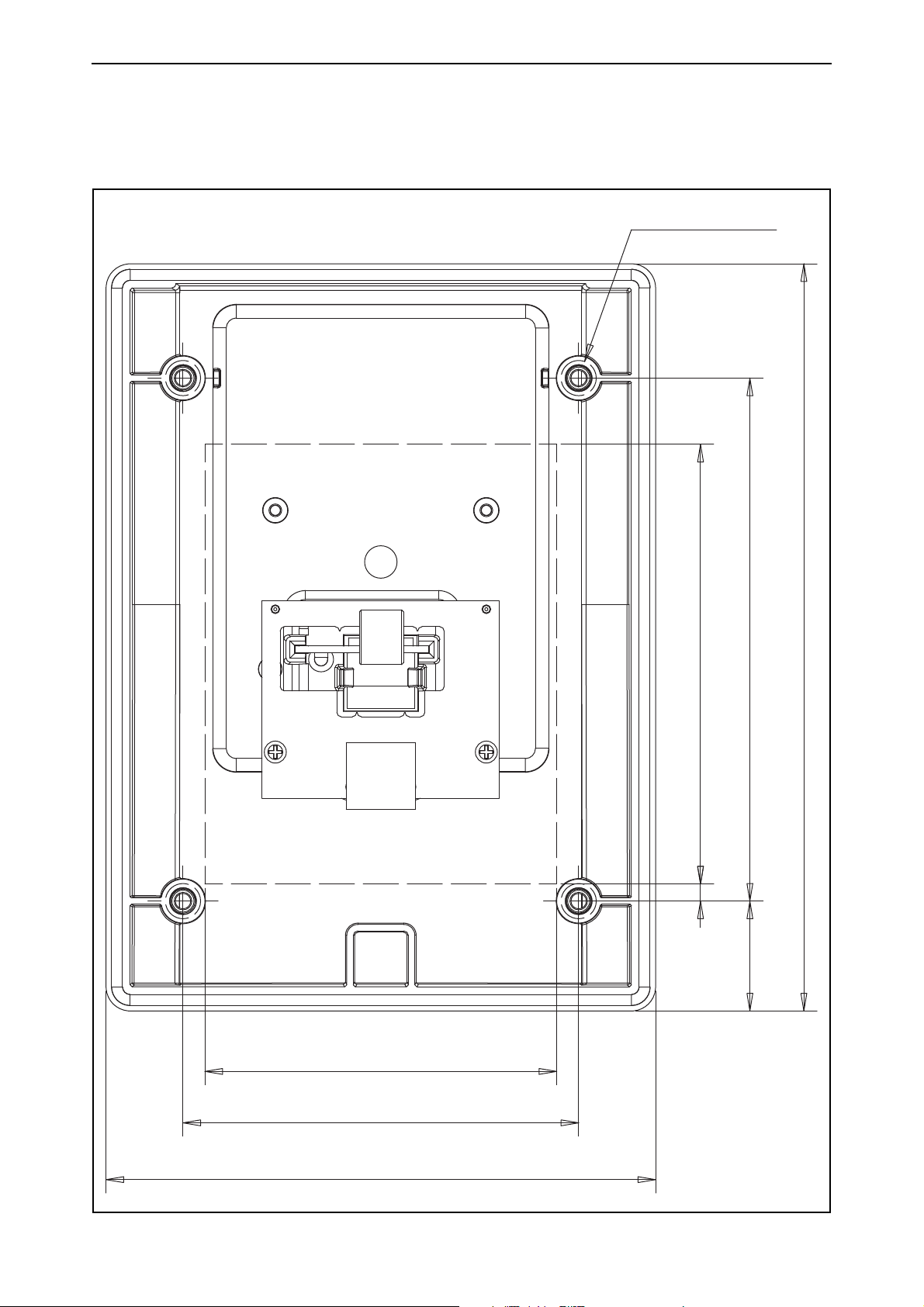
3. APPENDIX
The graphic is in real size. Use it to mark the cut-out for the door keypad as well as the screw holes.
Document code: DPD00459D
Page 6

6 APPENDIX
Document code: DPD00459D
22 18
Page 7

APPENDIX 7
125,0
70,3
100,257,4
Document code: DPD00459D
 Loading...