

Domestic hot water
Domestic Hot Water
Application guide
Intelligent solutions
with lasting eect
Visit devi.com

Table of content
Our quality management
system
and compliances
Along with full compliance with EU
directives and product approvals
ISO 9001 TS 16949
ISO 14001 PED
Let DEVI do the work
1. Application overview 4
2. System Description 5
3. System design 7
3.1 Heat loss calculation 7
3.2 Product selection 9
3.2.1 Heating cable selection 9
3.2.2 Thermostat/Controller
selection 11
3.2.3 Accessories selection 14
4. Safety instruction 18
4.1 DO's 18
4.2 DON'Ts 18
5. Case stories 19
6. Technical support 19
DEVI - an abbreviation of Dansk El-Varme Industri - was established in
Copenhagen, Denmark, in 1942. As from January 1st 2003 DEVI has become
a part of the Danfoss Group - Denmark's largest industrial Group. Danfoss
is one of the world's leading companies within heating, cooling and airconditioning. The Danfoss Group has more than 23.000 employees and
serves customers in more than 100 countries.
DEVI is Europe’s leading brand of electric cable heating systems and electric
pipe heating systems with over 70 years of experience. The development of
electric floor heating system takes place in Denmark, where the head office
is situated while heating elements (cables and mats) are manufactured by
Danfoss in EU.
Domestic Hot Water temperature
maintenance system
This design guide presents DEVI’s recommendations for design and
installation of Domestic Hot Water system. It provides guidance for a heating
cable layout, electric data and system configurations.
Following DEVI’s recommendations will ensure energy efficient, reliable and
maintenance free solution for constant wattage heating cables with 20 year
warranty, self-limiting heating cables with 5 years of warranty.
1. Application
overview
Modern living requires buildings to
have hot water available whenever
and wherever needed – and preferably immediately. The building regulations demand domestic hot water
systems to ensure best comfort and
efficiency as well as the Legionella
control measures.
DEVIhotwatt™ systems ensure continuous and reliable supply of with
the possibility to disinfect Domestic
Hot Water (DHW). DEVIhotwatt™ is
a self-limiting heating cable that is
used for temperature maintenance of
hot water supply.
DEVIhotwatt™ systems compliments
domestic hot water systems and enables
the unique possibility to temperature
control and disinfect, both for circulation systems and uniquely also for single
pipe systems from source to tap.
DEVIhotwatt™ systems complies with
IEC 62395-2:2013.
Benefits
• Unique opportunity - allows the installation
of a single pipe hot-water system, that includes
thermally controlled and disinfected hot water
at the tap.
• Lower initial investment the electric
pipe tracing in DHW system without
circulation requires less pipes and insulation
(approximately 50%), less valves, less pumps
and installation labor compared to the
recirculating system.
• DEVI pipe tracing systems ensure hot water
in all taps and savings when a circulating pipe
system is unnecessary.
• DEVI heating cable reduces water waste as you
can get hot water immediately.
• Protection against Legionella – DEVI system
maintains water supply at the required
temperature level and provides disinfection to
combat the bacteria.
• DEVIhotwatt™ system is the Perfect solution
to be used in domestic hot water systems.
Including systems supplied by low temperature
district heating.
• Energy efficient - Self limiting heating cables
provide power where needed, adapting their
output according to the ambient temperature.
Less pipes and smaller boilers will in term mean
lower heat losses.
• The heating cable is flexible and easy to
install as it can be cut to length, right on site
and installed directly on the pipe system.
4 Application guide · Domestic hot water · ©DEVI
2. System Description
DEVI Pipe tracing systems
will be required in the
following cases:
• Low-temperature, heat
source is supplying DHW
at lower than 50 °C
• The ambient
temperature variation is
significant
• Tap is located so far
away that the hot water
temperature is not
properly maintained
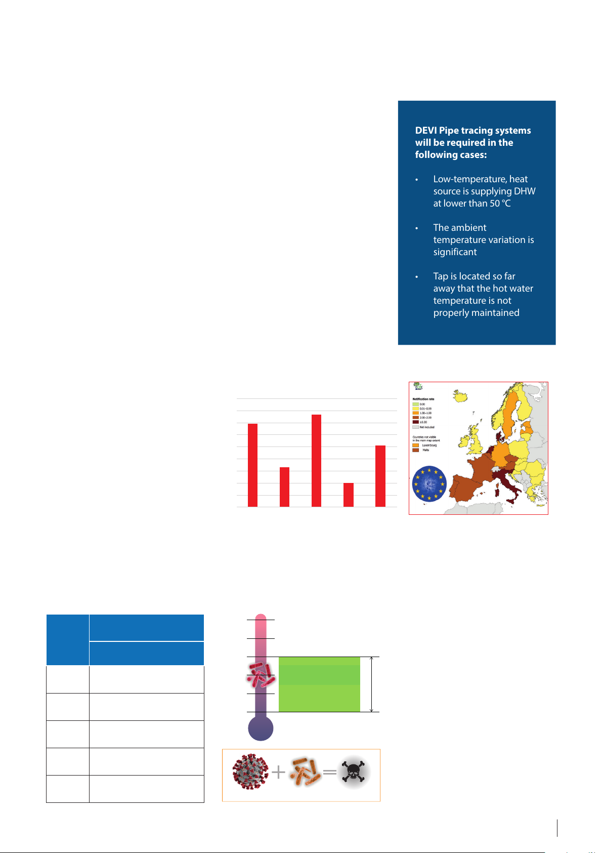
1800
1600
1400
1200
1000
Since 1998 the EU Drinking Water
Directive (98/83/EG) in EN 806-2
has established standards for hot
water in pipes that should not drop
below 50 °C. The building regulations
as well as global trends are demanding DHW systems to provide the best
comfort, energy efficiency and the
Legionella mitigation measures.
General design principles aim to
provide uniform water temperature,
which should also enable temperatures to combat Legionella growth.
The general recommendation for
DHW is to maintain the heat source
temperature between 50-60 °C
(IEC 62395-2:2013).
Water heating is provided by centralized or decentralized sources, Centralized water heating systems (district
heating) often have large distribution
network that might contribute to
temperature inconsistencies.
According to IEC 62395-2:2013 guidelines:
”For disinfection purposes min 55 °C
is typically required for hot water installations fitted with mixing valves”.
In the case that the water temperature
of DHW systems cannot achieve the
recommended level, risks of possible
water waste and Legionella will arise,
therefore a supplementary electrical
tracing system is recommended.
The Legionella bacteria which is commonly found in many types of water
worldwide. The bacteria can create a
potentially fatal type of pneumonia
commonly by inhalation.
The Legionella bacteria multiply best
where temperatures are between
20-45 °C and nutrients are available. A
method used to reduce the risk from
the Legionella bacteria, is to control the
water temperature, which is easy to do
with help of DEVI pipe heating system .
The DEVI pipe heating system for
DHW, maintains the water at the desired nominal temperatures or heats
(disinfects) it when needed.
1389
800
600
400
200
0
FranceGermanyItaly Netherlands Spain
Source: ECDC Annual Epidemiological Report for 2017 Source: ECDC Annual Epidemiological Report for 2017
664
1535
1018
393
Temperature and disinfection time
Tempera-
ture of
disinfec-
tion [°C]
55 2 h 00 minute
60 0 h 40 minute
65 0 h 26 minute
70 0 h 20 minute
75 0 h 10 minute
Time settings for thermal
disinfection
Recomended
70°C
60°C
50°C
40°C
30°C
20°C
Any disease Legionella Higher risk
At 70°C pasteurization process takes 20 min
At 58°C pasteurization process takes 50 min
At 50°C Legionella will no longer multiply
Ideal growth range
35-46 °C
growth range
5Application guide · Domestic hot water · ©DEVI
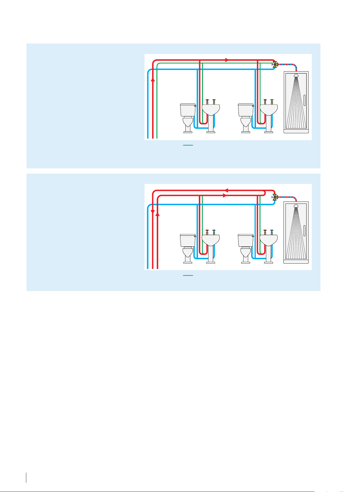
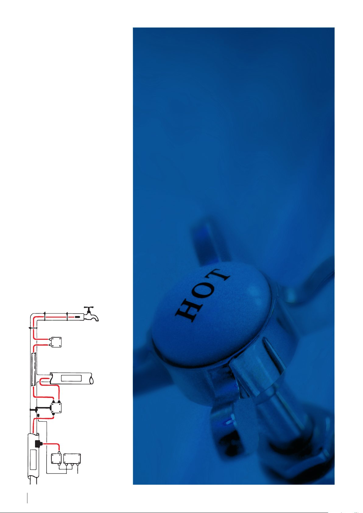
Heat tracing in DHW (Domestic Hot Water) systems
DHW system, single pipe system
(without circulation) - the cable
modifies its output and thereby
temperature according to the
conditions along the installation. This
means that the DHW system is heated
corresponding to heat losses, thus
maintaining and/or controlling the
temperature.
The more often the hot water tap is
turned on, the less the hot water temperature maintenance system needs to
be activated assuming a water supply
with a higher or equal temperature to
the respective requirement.
DHW system with circulation continuous circulation of hot water
to ensure that hot water is available
at any of the taps.
Self-limiting heating cable
In case of DHW with circulation - pipe
tracing can be installed to ensure
loop temperature. Thereby aiding the
system to maintain temperatures at
the required level.
DHW systems can also be installed to
secure pipes where circulation can't
be provided to ensure the wanted/
needed temperature.
The DEVIhotwatt™ pipe tracing in
DHW system without circulation
requires less pipes, less valves, less
pumps and installation labor compared to the Recirculating system.
• Approximately 50% less pipes – less
water volume in the pipes, thus
smaller boiler can be used.
• Energy consumption reduction, as
heat losses from the pipes will be
reduced by a significant amount.
Self-limiting heating cable
• Less maintenance cost, as less
mechanical parts and pumps.
• Saving water – DEVI pipe heating
system attached to the pipes keeps
water at the desired temperature
along the pipe system, so hot water
is immediately provided, when
demanded, and with minimum
water loss.
The DEVI pipe heating system insures
that DHW is supplied, independent of
the pipes length, and reduces the risk
of localized temperature fluctuations
by heating only where needed.
DEVI pipe heating system is insuring
automatic maintenance of the
required temperature 24/7.
6 Application guide · Domestic hot water · ©DEVI

3. System design
Following pages provide an easy design guide for selection of a Domestic hot water system.
The recommendations are provided relates to self-limiting cables, as well as thermostats and accessories.
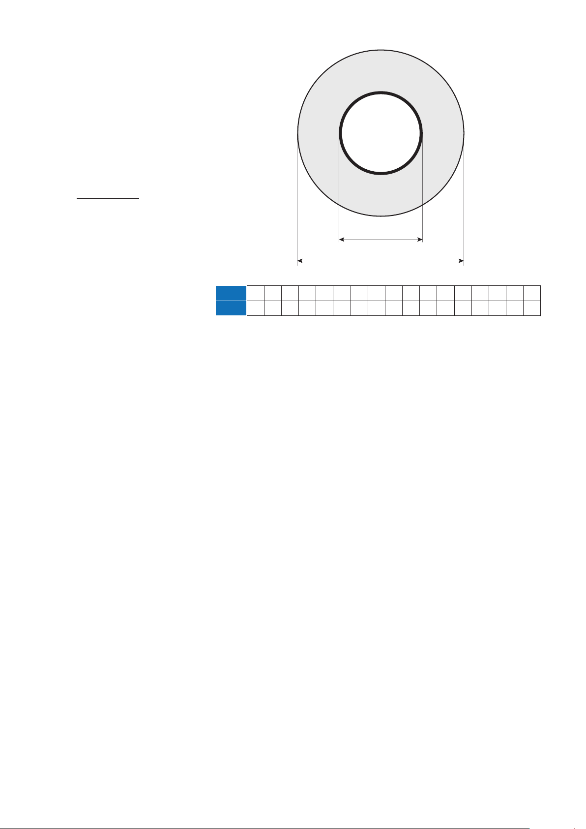
3.1 Heat loss calculation
Linear output of a heating cable (W/m),
which is installed on hot water pipe,
of heating cable along 1 pipe length
or a higher W/m cable.
should be at least the same as heat loss
(Q, W/m) of the pipe. Heat loss depends
on the following: pipe diameter, insula-
Heat and losses of pipe systems [W/m]
tion thickness, temperature inside pipe
and ambient/surrounding temperature.
Increased heat loss can lead to the
necessity of installing 2 or more lines
The table below shows the heat
loss for 1 meter of pipe (q
pipe
) for
various pipe dimensions, insulation
thicknesses and temperatures.
Required minimal outputs in [W/m], for straight pipelines (without flanges, valves or T-branches).
Inside pipe
diameter
Outside pipe
diameter*
Insulation
thickness
10 mm
20 mm
30 mm
40 mm
50 mm
75 mm
* NPS - Nominal Pipe Size, DN - diamètre nominal/nominal diameter/Durchmesser nach Norm.
Values in table can be calculated with help of formula on next page.
inch (NPS*) ½ ¾ 1 1¼ 1½ 2 2½ 3 3½ 4 4½ 5 6 8 10 12
mm (DN*) 15 20 25 32 40 50 65 80 90 100 115 125 150 200 250 300
mm 21 27 34 42 48 60 73 89 102 114 127 141 168 219 273 324
T, °C Heat loss for 1 meter of pipe, W/m ( λ = 0,04, Safety factor = 1,3)
20 9,8 11,8 14,1 16,8 18,8 22,7 27,0 32 36 40 45 49 58 75 92 109
25 12,2 14,7 17,6 21,0 23,4 28,4 34 40 46 51 56 62 73 93 115 136
30 14,6 17,7 21,2 25,2 28,1 34 40 48 55 61 67 74 87 112 139 164
40 19,5 23,6 28,2 34 38 45 54 64 73 81 89 98 116 149 185 218
60 29,3 35 42 50 56 68 81 97 109 121 134 148 174 224 277 327
80 39,0 47 56 67 75 91 108 129 146 162 179 197 232 299 370 436
100 48,8 59 71 84 94 114 135 161 182 202 223 246 290 374 462 545
20 6,1 7,2 8,4 9,8 10,8 12,8 14,9 17,6 19,7 21,7 23,9 26,2 31 39 48 56
25 7,7 9,0 10,5 12,2 13,5 16,0 18,7 22,0 24,7 27,1 30 33 38 49 60 70
30 9,2 10,8 12,6 14,6 16,2 19,2 22,4 26,4 30 33 36 39 46 58 72 84
40 12,2 14,4 16,8 19,5 21,6 25,6 30 35 39 43 48 52 61 78 96 112
60 18,4 21,6 25,2 29,3 32 38 45 53 59 65 72 78 92 117 143 168
80 24,5 28,7 34 39 43 51 60 70 79 87 95 105 122 156 191 224
100 30,6 36 42 49 54 64 75 88 99 109 119 131 153 195 239 281
20 4,8 5,6 6,4 7,4 8,1 9,4 10,9 12,7 14,1 15,4 16,9 18,4 21,4 27,0 33 38
25 6,0 7,0 8,0 9,2 10,1 11,8 13,6 15,8 17,6 19,3 21,1 23,0 26,7 34 41 48
30 7,3 8,4 9,6 11,0 12,1 14,1 16,3 19,0 21,2 23,2 25,3 27,6 32 40 49 58
40 9,7 11,2 12,8 14,7 16,1 18,8 21,8 25,3 28,2 31 34 37 43 54 66 77
60 14,5 16,7 19,3 22,1 24,2 28,3 33 38 42 46 51 55 64 81 99 115
80 19,4 22,3 25,7 29,4 32 38 44 51 56 62 68 74 86 108 131 154
100 24,2 27,9 32 37 40 47 54 63 71 77 84 92 107 135 164 192
20 4,2 4,7 5,4 6,1 6,7 7,7 8,8 10,2 11,3 12,3 13,4 14,5 16,8 21,0 25,4 29,6
25 5,2 5,9 6,7 7,7 8,3 9,6 11,0 12,7 14,1 15,4 16,7 18,2 21,0 26,2 32 37
30 6,2 7,1 8,1 9,2 10,0 11,6 13,2 15,3 16,9 18,4 20,1 21,8 25,2 31 38 44
40 8,3 9,5 10,8 12,2 13,3 15,4 17,7 20,4 22,6 24,6 26,7 29,1 34 42 51 59
60 12,5 14,2 16,2 18,4 20,0 23,1 26,5 31 34 37 40 44 50 63 76 89
80 16,6 19,0 21,6 24,5 26,6 31 35 41 45 49 53 58 67 84 102 118
100 20,8 23,7 27,0 31 33 39 44 51 56 61 67 73 84 105 127 148
20 3,7 4,2 4,8 5,4 5,8 6,7 7,6 8,7 9,6 10,4 11,2 12,2 14,0 17,4 20,9 24,3
25 4,7 5,3 6,0 6,7 7,3 8,3 9,5 10,8 11,9 13,0 14,1 15,2 17,5 21,7 26,2 30,4
30 5,6 6,3 7,1 8,0 8,7 10,0 11,4 13,0 14,3 15,6 16,9 18,3 21,0 26,0 31 36
40 7,5 8,4 9,5 10,7 11,6 13,3 15,1 17,3 19,1 20,7 22,5 24,4 28,0 35 42 49
60 11,2 12,7 14,3 16,1 17,4 20,0 22,7 26,0 28,7 31 34 37 42 52 63 73
80 14,9 16,9 19,0 21,4 23,2 26,6 30 35 38 41 45 49 56 69 84 97
100 18,6 21,1 23,8 26,8 29,0 33 38 43 48 52 56 61 70 87 105 121
20 3,1 3,5 3,9 4,3 4,6 5,2 5,8 6,6 7,2 7,8 8,4 9,0 10,2 12,5 14,9 17,2
25 3,9 4,3 4,8 5,4 5,8 6,5 7,3 8,3 9,0 9,7 10,5 11,3 12,8 15,6 18,6 21,5
30 4,7 5,2 5,8 6,4 6,9 7,8 8,8 9,9 10,8 11,7 12,6 13,5 15,4 18,8 22,4 25,7
40 6,2 6,9 7,7 8,6 9,2 10,4 11,7 13,2 14,4 15,6 16,8 18,0 20,5 25,0 29,8 34
60 9,3 10,4 11,6 12,9 13,8 15,6 17,5 19,8 21,7 23,3 25,1 27,0 31 38 45 51
80 12,5 13,9 15,5 17,2 18,4 20,9 23,4 26,4 28,9 31 34 36 41 50 60 69
100 15,6 17,4 19,3 21,5 23,0 26,1 29,2 33 36 39 42 45 51 63 75 86
To define the heat loss follow the
pipe diameter (in [mm] or [inch]) at
the top bar of the table towards the
row with the insulation thickness and
using the appropriate temperature
difference you will find the heat loss
value at the crossing point.
For this table λ of insulation
material is 0,04 W/mK (e.g. mineral
wool) and safety factor is 1,3.
7Application guide · Domestic hot water · ©DEVI
The most important factors to define
the pipe heat losses are the following:
• Pipe diameter
• Insulation thickness
• Difference between inside
(desired maintained
temperature).
The following formula is used for
heat losses calculation for total
length of a pipe to be protected:
Q [W]=
2 · π · λ · l · (t
ln(D/d)
a
- tp)
1, 3 ,
where:
D - Outside pipe diameter incl. insulation, [m],
d - Pipe diameter without insulation [m],
l - Total length of pipe, [m],
tp - Desired maintained temperature, [°C],
ta - Outside temperature, [°C],
λ - Thermal conductivity of insulation, [W/m·K],
1,3 - Safety factor.
λ value for standard insulation
material (like glass wool or styropor),
is set to 0,04 W/m·K.
ln(D/d)
(D/d)
0,0
1,0
0,4
1,5
0,7
2,0
0,9
2,5
1,1
3,0
1,3
3,5
1,4
4,0
Heat loss values from the table on
the previous page calculated by the
above formula and divided by total
pipe length. The obtained values are
in [W/m].
t
a
t
p
d
D
1,5
1,6
1,8
1,9
2,1
2,2
2,3
2,7
4,5
5,0
6,0
7, 0
8,0
9,0
10,0
15, 0
Natural logarithm (ln) values for D/d
ratio: X = D/d.
3,0
20,0
3,2
25,0
8 Application guide · Domestic hot water · ©DEVI

3.2 Product selection
This section will show how to choose the correct heating element, control device and what accessories to use for the
installation.
3.2.1 Heating cable selection
Self-limiting cables are often used for
pipe systems with many branches,
because it's easier to adjust the cable
length to appropriate pipe length.
The self-limiting behavior of the cables,
provides output adjustment based on
the temperature (pipe and ambient),
this a rather useful feature. However
a thermostat for self-limiting cable
regulation is a must.
When choosing a self-limiting
heating cable it's essential to
investigate whether the heating
cable can provide the required
output at the desired temperature.
How to read the graph
Draw a line from the desired
temperature value (X-axis) and a
calculated heat loss output (Y-axis).
Afterwards find a heating cable with
output values higher (Y-axis) than
the cross point of temperature and
output lines.
Example (values from Previous page)
• Pipe diameter d = 25 mm
• Insulation thickness = 30 mm
• Thermal conductivity value for
insulation λ = 0,04
• Desired temperature tu = +45 °C
35
30
25
20
Emission of heat, W/m
15
Calculated
heat loss
Q = 8 W/m
10
5
5 10 15 20 25 30 35 40 45 50 55 60 65 70
• Minimum outside temperature
to = +20 °C
Heat loss Q is calculated by the
formula of Step 1 or from the table on
page 7: Q = 8 W/m.
This would then promt the choice to
be DEVIhotwatt 55 for an output of
9 W/m at 55 °C
DEVIhotwatt™ 70
DEVIhotwatt™ 55
DEVIhotwatt™ 45
12 W/m
7 W/m
Desired temperature
tu = +45 °C
9 W/m
Pipe temperature, °C
The pipe tracing system consists of a
self-limiting heating cable, installed
on a pipe along its whole length, and
providing hot water instantly, even
at faucets placed far away from pipe
draw off.
Overjacket
Protective braid
Insulation
Fig. 3 - Self-limiting cable construction
• 1,3 mm² nickel plated cooper bus wires
• Radiation Cross-linked Semiconductive
Heating Matrix
• Radiation Cross-linked Primary Dielectric
insulation
The system must be controlled by an
electronic regulator to maintain the
temperature and to run disinfection
ensuring safe and enabling the
option to maintain a Legionella free
water supply.
Self-limiting heating element
Bus wires
• Tinned copper braid
• Polyolen overjacket
The DEVIhotwatt™ is a self-limiting
heating cable that is used for
temperature maintenance of hot
water and other fluids which require
certain temperature levels.
The self-limiting capability of the
cable ensures cable output regulation
according to temperature to which
the cable is exposed, hence the selflimiting effect.
9Application guide · Domestic hot water · ©DEVI

DEVIhotwatt™ 45 (B), DEVIhotwatt™ 55 (B), DEVIhotwatt™ 70 (B)
The DEVIhotwatt™ is a self-limiting heating cable that is used for
temperature maintenance of hot water supply and other uids that need
to maintain a certain temperature.
The self-limiting capability of the cable ensures that the output of the
cable increase or decrease according to ambient temperature.
DEVIhotwatt™ ensures hot water in all taps and savings when circulation
of the whole pipe system is unnecessary.
The cable is not approved for use in drinking water.
Type
Nominal voltage 230 V AC
Nominal output (min-max) :
DEVIhotwatt™ 45
DEVIhotwatt™ 55
DEVIhotwatt™ 70
Outer sheath:
DEVIhotwatt™ 45
DEVIhotwatt™ 55
DEVIhotwatt™ 70
Maximum permissible use temperature
Minimum installation temperature -50 °C
Cable dimensions 11,8 mm × 5,8 mm
Minimum braid coverage 70%
Maximum resistance protective braid 18,2 Ω/Km
Bending Ø, min. 50 mm (Ø to the inside of the tape)
Max. installation length
- with 10 A circuit breaker 55 m
IP Class IPX7
Value
7 W/m @ 45 °C (6,5-9,5 W/m @ 45 °C)
9 W/m @ 55 °C (8,5-13,0 W/m @ 55 °C)
12 W/m @ 70 °C (11,3-15,2 W/m @ 70 °C)
Black, TPE
Green, TPE
Red, TPE
80 °C, powered
100 °C, unpowered
Maximum heating circuit length on a pipe, with circuit breaker
with C-characteristic
"Circuit breaker size" 6A 10A 16A
"start-up
temperature", [°C]
DEVI-hotwatt 45 72 77 86 92 119 129 144 153 191 203 230 231
DEVI-Hotwatt 55
-25 -10 +10 +20 -25 -10 +10 +20 -25 -10 +10 +20
52 56 61 65 86 93 102 108 138 148 164 173
Benefits
• The cables can
be cut to length
on site providing
quick installation.
• Automatic
compensation for
heat loss along
the pipe assuming
cable has more
output capability
than heat loss
present.
• Economical, selflimitting
• PVC free
• Limited preplaning of the
installation
DEVI-Hotwatt 70 24 27 42 59 37 45 71 99 64 72 113 146
"Circuit breaker size" 20A 25A 32A
"start-up
temperature", [°C]
DEVI-hotwatt 45 231 231 231 231 231 231 231 231 231 231 231 231
DEVI-Hotwatt 55 173 185 188 188 188 188 188 188 188 188 188 188
DEVI-Hotwatt 70 80 90 142 146 103 113 146 146 133 143 146 146
-25 -10 +10 +20 -25 -10 +10 +20 -25 -10 +10 +20
10 Application guide · Domestic hot water · ©DEVI

3.2.2 Thermostat/Controller selection
Temperature regulation
Self-limiting heating cables require a
thermostat for temperature control.
The thermostat ensures maintaining
desired temperature.
Domestic hot water systems are
required to have sensors mounted on
each hot water pipe system to ensure
proper control.
thermostat
on-pipe mounted sensor
thermostat
on-pipe mounted sensor
If the size of the heating cable
exceeds the maximum limit defined
by the thermostat or fuse.
The load of the heating cables
can be distributed by means of
external relays / contactors or by
use of the multiple relays within the
DEVIreg Hotwater controller. In such
installations, one thermostat can
regulate several heating elements.
When load distributing, please
do not exceed maximum cable
lengths mentioned on step 10.
Temperature regulation using onpipe sensors
This type of installation, where the
sensor is placed directly on pipe
under insulation, is more precise and
energy efficient way of regulation.
thermostat
on-pipe mounted sensor
Pipe of different lengths. Installation completed with 3 individual thermostats, this could also be
achieved using one DEVIreg Hotwater.
Sensor placing
Sensors for Domestic hot water
systems should be installed, at the
estimated most representative
position on the pipe.
Sensor placement for DEVIReg
Hotwater should be done such,
that the hottest and coldest
spot on pipe is measured, as the
DEVIreg Hotwater calculates a user
configurable mean temperature.
11Application guide · Domestic hot water · ©DEVI
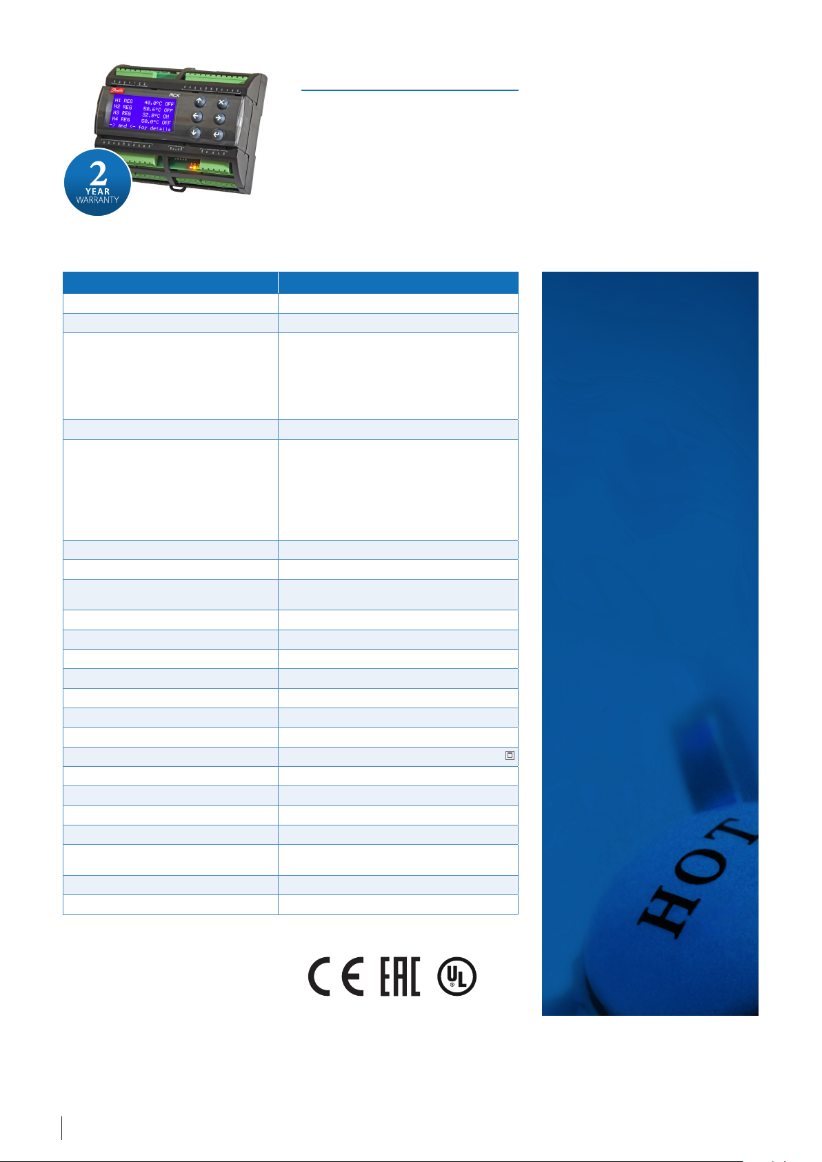
DEVIreg™ Hotwater
DEVIreg™ Hotwater is an electronic programmable controller with 4 channels
for on DIN rail mounting. Every channel can be set Individually to maintain hot
water with the option to disinfect manually, or on a schedule. The channels sensors can be selected between 7 dierent temperature sensors including NTC 15
kOhm at 25 °C. Building Management System (BMS) control is possible through
the Modbus RS485 serial interface.
DEVIreg™ Hotwater has been developed to give the user easy setup, control
of their hot water system, along with the option to disinfect. The controller allows up to 4 channels to be operated, each
capable of controlling a separate pipe system. 2 sensors have to be used to measure the temperature for each channel.
Type
Nominal voltage 110/230 V AC, 50–60 Hz
Power consumption, max. 20 V A
Relay load:
Resistive (inductive, cos(phi sign) = 0,6)
Total current load limit
C1-NO1, C2-NO2
C3-NO3-NC3, C4-NO4-NC4
C8-NO8-NC8
Sensor inputs Analog inputs AI1-AI8
Compatible sensors NTC15k (15 kOhm @ 25 °C) (standard)
Digital inputs DI1-DI8, voltage free contacts, on/o inputs
Connection specication Grouped screws plug-in connectors
Cable specication for connectors termi-
nals
Battery back-up time, min. 48 hours
Ball pressure test 125 °C
Pollution degree 2 (domestic use)
Controller type 1 C
Operating temperatures and conditions CE: -20T60 / UL: 0T55, 90% RH non-condensing
Storage temperature and conditions -3085, 90% RH non-condensing
IP class IP40 only on the front cover
Protection class Class II Immunity against voltage surges Over Voltage Category II
Dimensions (H/W/D), DIN dimension : 110(122) 138 70 mm, 8 DIN modules
Mounting method DIN rail, complying with EN 60715
Weight, net 511 g
Menu languages:
Base controller Danfoss MCX08M2, item no. 080G0307
Software class A
Value
32 A
10 (3,5) A (100 000 cycles)
6 (4) A (100 000 cycles)
6 (4) A (100 000 cycles)
NTC10k (10 kOhm @ 25 °C)
NTC5k (5 kOhm @ 25 °C)
NTC2k (2 kOhm @ 25 °C)
NTC100 (100 kOhm @ 25 °C)
NTC16k (16,7 kOhm @ 100 °C)
PT1000 (1000 Ohm @ 0 °C)
0,2-2,5 mm²
GB,DE,BG,CZ,DK,ES,EE,FI,FR,HR,HU,LT,LV,NL,NO,
PL,PT,RO,RU,SE,SR,SI,SK,TR,UA,CN.
Benefits
• 4 independent channels
• 2 control modes:
– Hot water
maintenance
– Hot water
maintenance with
disinfection
• User denable
accuracy
• Compatible with 7
sensors types
• Sensor failure
monitoring
• Accurate temperature
control
• Alarm functions
• Multilanguage menu
• Graphic LCD display
• BMS control
Compliance:
Low Voltage Directive 2014/35/EU
EMC Directive 2014/30/EU
EN/IEC 60730-1 + EN/IEC 60730-2-9
12 Application guide · Domestic hot water · ©DEVI
Certicates:
DEVIreg™ Hotwater + 2 sensor NTC 15kOhm
110/230 V AC
Item no. Product name Type EAN no.
140F1133 DEVIreg™ Hotwater Programmable controller with 2 Wire sensor NTC 15 kOhm at 25 °C, 3 m 5703466249680
Accessories
Item no. Product name Description EAN no.
140F1091
140F1098
Sensor 3 m, 15 kOhm, Santropene
Temperature Sensor 10 m NTC 15k Santropene
Wire sensor, 2x0,75 mm², NTC 15 kOhm at 25 °C, Ø5x18
mm, black Santropene (TPV), IP 67
19121445 Sensor cable 40 m, 15 kOhm, Santropene 5703466115015
140F1092 Outdoor sensor 2,5 m, 15 kOhm, PVC
140F1097
Silicon sensor for DEVIreg™ 330
(60-160°C), NTC 16,7 kOhm @ 100°C
Wire sensor, 2x0,75 mm², NTC 15 kOhm at 25 °C, Ø8 mm,
white PVC outer sheath, IP 67
Wire silicon sensor, 2,5 m, 2x0,75 mm²,
NTC 16,7 kOhm at 100 °C, IP 65
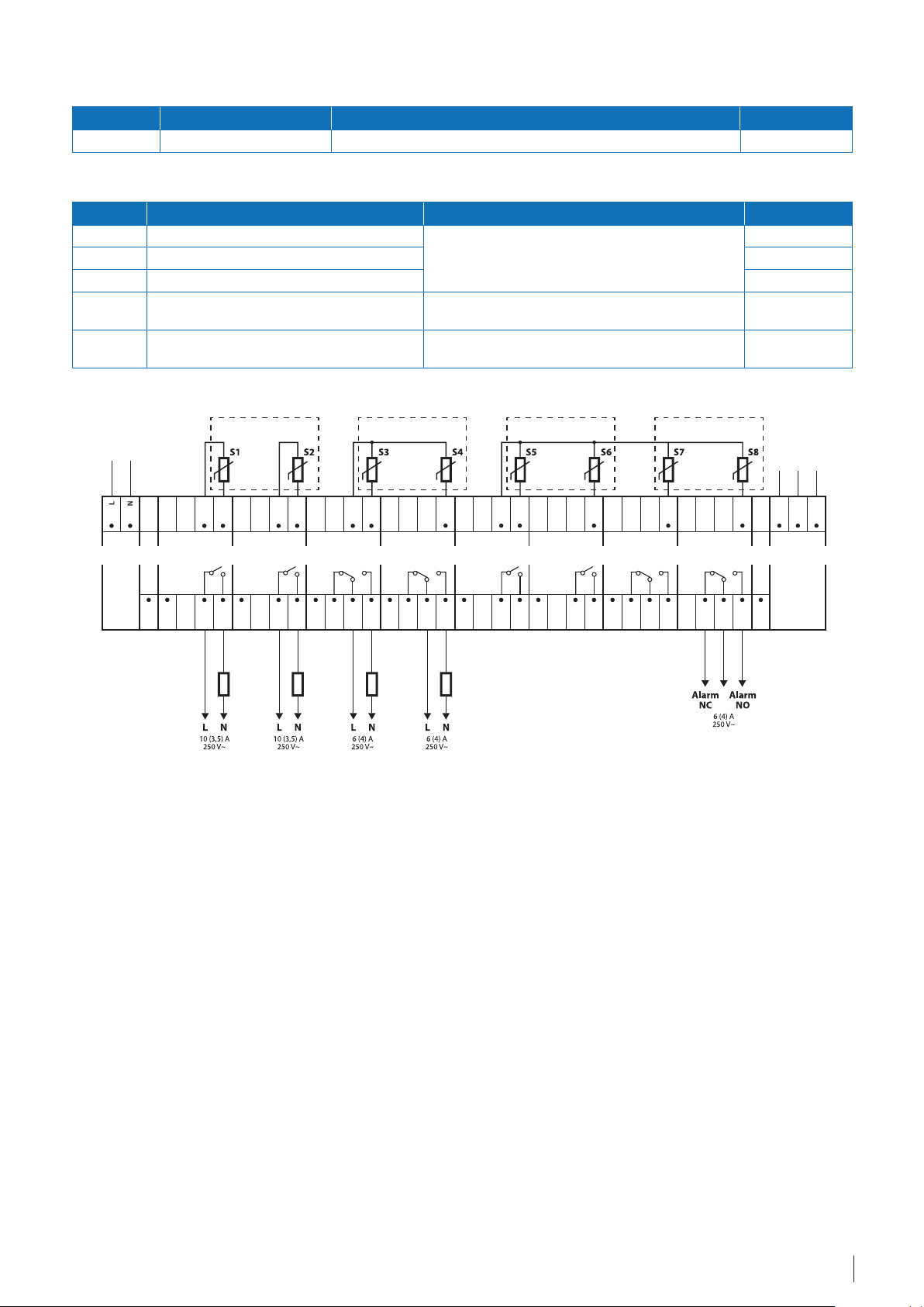
Connection scheme DEVIreg™ Hotwater
5703466209301
5703466210734
5703466209318
5703466209707
Power
COM
DI 1-4
DI 1
S - temperature Sensor
H - Heating element
for H2 for H3for H1
AI 1
COM
C 1
NO 1
DI 2
AI 2
COM
C 2
NO 2
DI 3
NC 3
AI 3
COM
AI 3-4
C 3
NO 3
DI 4
H1 H2 H3 H4
NC 4
for H4
RS485
(Modbus)
D -
AI 4
AI 5
COM
AI 5-8
AI 6
AI 7
AI 8
D +
GND
RS485
C 4
NO 4
DI 5
C 5
NO 5
DI 6
C 6
NO 6
DI 7
NC 7
C 7
NO 7
NC 8
DI 8
C 8
NO 8
COM
DI 5-8
13Application guide · Domestic hot water · ©DEVI
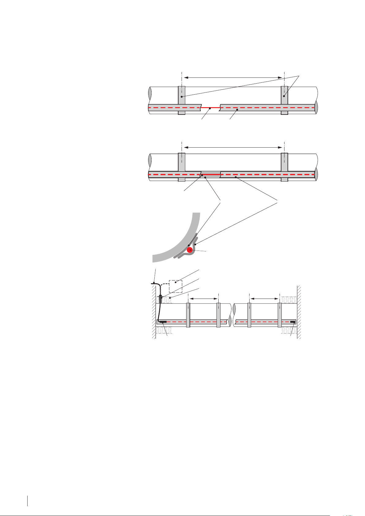
connection box
Output from
(part of a heating cable)
(part of a heating cable)
aluminum tapes
(pipe dimension Ø 150 mm)
heating cable
(under the tape)
aluminum tape
aluminum tapes
for cable attachment
to the pipe
metal
pipe
~1 m
app. 1,5 m tape
on 1 m of pipe
(pipe dimension Ø 150 mm)
3.2.3 Accessories selection
In case of metal pipes the heating cable
can be attached to the pipe by means
of an aluminum tape placed at intervals
of approx. 1 meter. Subsequently, the
total length of the heating cable needs
to be covered with aluminum tape,
securing cables to the pipe.
In case of the plastic pipes, before
mounting the cable onto the pipe, the
aluminum tape needs to be applied
on the pipe where the heating cable
will be placed. Other part of the
installation steps resembles that of the
installation on metal pipe.
For plastic pipe a temperature of
more than 60 degrees can't be
recommended, as this might weaken
the connections of the pipes.
The cable installed throughout the
pipe length needs to be covered
along its whole length with
aluminum tape to ensure good
contact with the pipe.
(between layers of aluminum tape)
metal
pipe
plastic
pipe
heating cable
heating cable
(under the tape)
~1 m
aluminum tape
~1 m
1st layer of tape
for cable attachment
to the pipe
app. 1,5 m tape
on 1 m of pipe
2nd layer of tape
app. 2,5 m tape
on 1 m of pipe
(pipe dimension Ø 150 mm)
On plastic pipes aluminum tape is
necessary both below and above
cable to ensure heat transfer.
All cables must be installed in parallel
passes; no spiral wrapping is allowed.
Hot water pipes shall be pressure
tested prior to installation of heating
cable and thermal insulation. Thermal
insulation shall not be installed until
heating cable installation is complete
and tested.
Cables must be fitted as shown
at 5 or 7 o’clock positions
when mounting two cables, or
alternatively at 6 o'clock when
mounting a single cable.
When the heating cable is
thermostat
connection mu
installed on pipes, the insulation
should be clearly marked with a
warning sign, e.g. “WARNING: 230
VOLT HEATING CABLES“ as stated
on our aluminum tape.
heating cable
(between layers of aluminum tape)
installation through the insulation
pipe insulation
~1 m~1 m
end mu
14 Application guide · Domestic hot water · ©DEVI

List of accessories:
Picture Name
Tape aluminium
38 mm x 50 m
DEVIconnecto B-A
Connection
DEVIconnecto
B-C Heating cable
connection
DEVIconnecto B-E End
termination
Description/Technical data
Self-adhesive, with 2-colour warning text,
max. 75 °C
Backing Aluminium foil
Adhesive Waterbased Acrylic
Liner Monosiliconized Paper
Adhesion/Steel 8 N/ 38 mm
Tensile strength 57,5 N/ 38 mm
Total thickness 60 m
Package 130 x 265 x 75 mm Art. no. 19808360
130 x 265 x 75 mm Art. no. 19808361
130 x 265 x 75 mm Art. no. 19808362
Art. no. 19805076
EAN no. 5703435003053
EAN no. 5703466103067
EAN no. 5703466103074
EAN no. 5703466103081
DEVIconnecto
B-S Connection
termination
DEVIconnecto B-T,
T-Junction + End
termination
DEVIconnecto B-TE2
Junction + 2 End
termination
DEVIconnecto B-TE3
Junction + 3 End
termination
DEVIconnecto B-X,
X-Junction + 2 End
termination
130 x 265 x 75 mm Art. no. 19808363
EAN no. 5703466103098
130 x 265 x 75 mm Art. no. 19808364
EAN no. 5703466103104
130 x 265 x 75 mm Art. no. 19808365
EAN no. 5703466103111
130 x 265 x 75 mm Art. no. 19808366
EAN no. 5703466103128
130 x 265 x 75 mm Art. no. 19808367
EAN no. 5703466103135
DEVIconnecto Bracket,
ref AH 61400005
Braket for installation outside the insulation Art. no. 19808390
EAN no. 5703466125021
15Application guide · Domestic hot water · ©DEVI

Picture Name
Sensor cable 3 m, 15
kOhm, Santropene
Temperature Sensor 10 m
NTC 15k Santropene
Temperature Sensor 40 m
NTC15k Santropene
Description/Technical data
Wire sensor
2x0,75 mm²,
NTC 15 kOhm
at 25 °C,
Ø5 mm, black
Santropene
(TPV) outer
sheath, IP 67,
Temp. range
-25 °C to 90 °C
Temp., ° Resistanse,
kOhm
-10 66,1
-5 52,5
0 41,1
5 33,2
10 27,0
15 22,1
20 18,2
25 15,0
30 12,3
35 10,4
40 8,7
45 7,4
50 6,2
Art. no. 140F1091
EAN no. 5703466209301
Art. no. 140F1098
EAN no. 5703466210734
Art. no. 19121445
EAN no. 5703466115015
Outdoor sensor 2,5 m,
15 kOhm, PVC, DIN
44574
Silicon temperature
sensor
for DEVIreg™ 330
(60-160°C),
NTC 16,7 kOhm @ 100°C
Wire sensor, 2x0,75 mm²,
NTC 15 kOhm at 25 °C,
Ø8 mm,
white PVC outer sheath, IP 67,
Temp. range -25 °C to 70 °C
Wire sensor, 2,5 m, 2x0,75 mm²,
NTC 16,7 kOhm at 100 °C,
Ø9 mm, IP 65,
Temp. range 50 °C to 170 °C
Art. no. 140F1092
EAN no. 5703466209318
Art. no. 140F1097
EAN no. 5703466209707
16 Application guide · Domestic hot water · ©DEVI

Insulation
bracket
Output from
Heating cable
Aluminium tape
Sensor
The recommended ways to mount the cable lines on the pipe
Selection of connection accessories for self-limiting heating cables
connection to box
thermostat
230V
Output from thermostat
230V
power cable
connection to box
17Application guide · Domestic hot water · ©DEVI

4. Safety instruction
Heating cables must always be installed
according to local building regulations
and wiring rules as well as the
guidelines in this installation manual.
De-energize all power circuits before
installation and service.
Residual current device (RCD)
protection is required.RCD trip rating
is max.30 mA.
The screen from each heating cable
must be connected to earthing
terminal in accordance with local
electricity regulations.
4.1 DO's
• For installation of cable and
thermostat/controller, always refer
to the local regulations/legislations
and respective manuals.
• Remember to fill out the warranty
sheet with the required information
as this will not be valid otherwise.
• Carefully complete the installation,
the cable can break when
overloaded.
• If any doubt arises consult you
manual or local DEVI department.
• Ensure that the cable is sufficiently
fixed and mounted according to
the manual.
Heating cables must be connected
via a switch providing all pole
disconnection.
The heating cable must be equipped
with a correctly sized fuse or circuit
breaker according to local regulations.
Never exceed the maximum heat
density (W/m or W/m²) for the actual
application.
Strongly recommended to use the
heating cable together with an
appropriate thermostat to secure
against overheating.
• Ensure that warning labels and
stickers (potentially tape) with
warning text is used to inform
about the heat traced cable.
• Install sensors where the
temperature is estimated to be
representative for the whole
installation, where 2 sensors
are needed for the thermostat/
controller please install at the
estimated extreme points (coldest
and hottest).
• To get the best performance of
the system and avoid failures it is
necessary to follow the installation
descriptions.
The presence of a heating cable
must be made evident by affixing
caution signs in the fuse box and in
the distribution board or markings
at the power connection fittings
and/or frequently along the circuit
line where clearly visible (tracing)
must be stated in any electrical
documentation following the
installation.
• To get the best performance of
the system it is strictly necessary
to calculate the correct heat
losses, for all dimensions of pipes
and the whole system. Using this
knowledge the cable with right
output can be chosen.
• Plan every installation step and
fixing point of the traced pipes
ahead of time and ensure that the
"run" is proper and possible.
• Ensure sensors are connected
according to the applicable
installation guide and/or
application guide.
4.2 DON'Ts
• Never make an installation without
thermostat.
• Never install cables where the heat
can't be dissipated, even with a
self-limiting cable the output will
never become zero and the cable
can overheat.
18 Application guide · Domestic hot water · ©DEVI
• Never let unauthorized personnel
install controllers/thermostats or
heating elements.
• Never use unauthorized
accessories.
• Never use our products (cables,
controllers, sensors, etc.) outside
provided temperature range.

5. Case stories
https://devi.danfoss.com/en/case-stories/?page=1
6. Technical support
The Electric Heating team is offering
valuable support to professionals
when it comes to preparing your
new projects.
We offer support for:
• Calculation of Electric Heating
system
• Development of drawings for
projects
• Preparation of the BoM (Bill of
Material)
• Recommendations for the
installation and operation of the
system
In order to clarify the project data
for different applications use the
following technical request forms, fill
in with your specifications and send it
to: EH@danfoss.com
https://devi.danfoss.com/en/support/
19Application guide · Domestic hot water · ©DEVI

08097147 & AB381952809354EN000101 | JUN 16, 2021
Intelligent solutions
with lasting eect
Visit devi.com
 Loading...