

Page 1

Service Kit Instructions
Displacement control kits
Replacement procedure
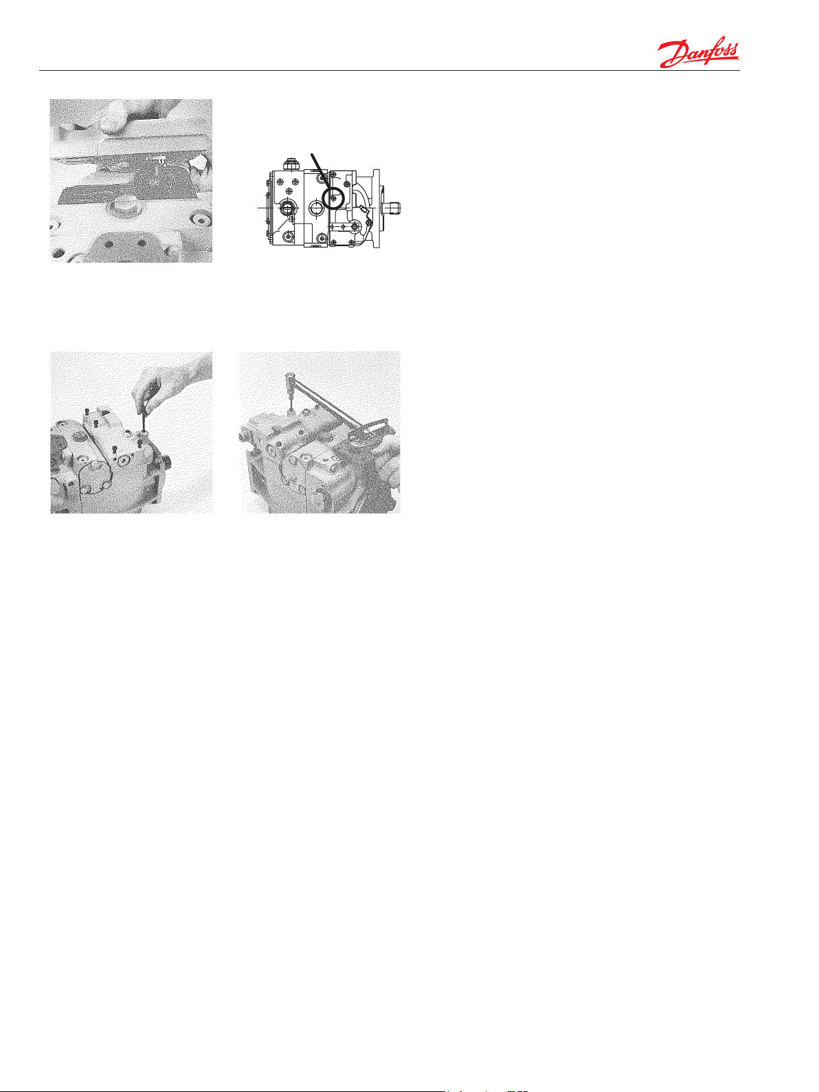
Fig. 1 - Remove mounting
screws
Fig. 2 - Remove control
Removing and installing displacement control (MDC,
HDC, EDC)
Thoroughly clean external surfaces of pump prior to
removal of control.
Using a 5 mm internal hex wrench, remove the six (6) control
mounting screws. Remove the original control and gasket
from housing.
CAUTION
Protect exposed surfaces and cavities from damage and
foreign material.
The orice check valve is located in the inner surface of the
control assembly. Remove the spring retainer and spring
from the orice check valve cavity of the original control and
then remove the orice check valve.
NOTE: Certain controls may have orices installed in the
servo feed and drain passages of the control. If such orices
are present, they must also be transfered to the replacement
control.
Fig. 3 - Orice check valve
components
30cc, 42cc,
55cc
Fig. 5 - Gaskets for MDCs, EDCs and earlier production
HDCs
30cc, 42cc,
55cc
Fig. 6 - Gaskets for later production HDCs
Fig. 4 - Orice check valve
installed
75cc, 100cc,
130cc
75cc, 100cc,
130cc
Install the orice check valve in the cavity of the replacement
control and then install the spring and spring retainer to hold
the orice check valve in position.
In preparation for installing the replacement control, place a
new gasket on the housing.
Later production hydraulic displacement controls (HDCs)
use a dierent gasket from earlier production HDCs, manual
displacement controls (MDCs) and electric displacement
controls (EDCs). Refer to the accompanying illustrations for
identication.
WARNING
Failure to use the appropriate gasket may result in uncontrolled pump displacement.
Check that the control orice check valve, spring, and retainer
are in their proper position in the replacement control.
© Danfoss, 2014 AN00000103un-US | BLN-10031 • Rev DB • May 2016 1
Page 2
For 042 frame size pumps, the
sealing washer must be installed
under the head of this screw.
Engage the pin on the control linkage in the mating hole in
the link attached to the swashplate. Set control into position.
Feel for pin engagement by tipping the control before installing the mounting screws. The control will not tip more than
±10° if the pin is properly engaged.
WARNING
Uncontrolable vehicle or load movement will occur upon
start-up if control is installed without engagement of
control feedback link pin into swashplate link.
Fig. 7 - Assemble control
linkage
Fig. 9 - Install control
screws
Fig. 8 - Location of sealing
washer for 42cc pumps
Fig. 10 - Torque mounting
screws
In case of non-engagement remove the control and repeat the
above procedure.
Torque the screws to 12 ft.lbsf. (16 Nm).
NOTE: When reinstalling the Manual Displacement Control
linkage, the control shaft nut should be torqued to 100 in.lbsf.
(11.3 Nm) MAXIMUM. If a Manual Displacement Control
equipped with a neutral start switch is being replaced, check
the operation of the switch and adjust if necessary.
WARNING
Vehicle or load movement can result from improperly
adjusted control neutral. Follow Service Manual procedure for adjusting “neutral” after start-up.
Always disable vehicle (wheels raised o the ground,
work function disconnected, etc.) to prevent movement
upon start-up.
© Danfoss, 2014 AN00000103un-US | BLN-10031 • Rev DB • May 2016 2
 Loading...