

Page 1
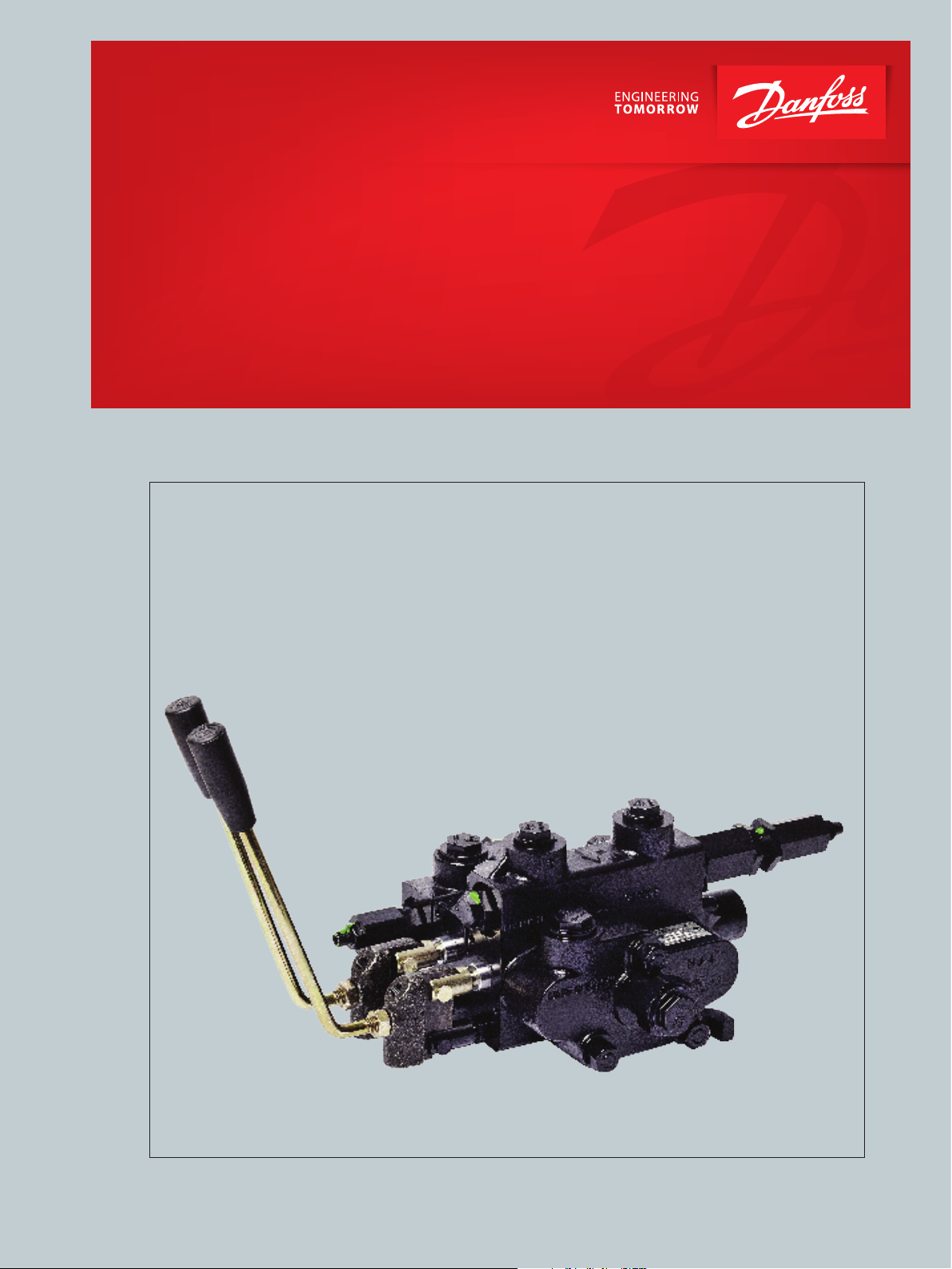
Directional Control Valve
Technical Information
powersolutions.danfoss.com
Page 2

Directional Control Valves Technical Information:
Contents
PRODUCT OVERVIEW Flexibility of design ........................................................................................................................................3
Circuit options ................................................................................................................................................. 3
Capability .......................................................................................................................................................... 3
Actuation options .......................................................................................................................................... 3
Modular valves ................................................................................................................................................ 4
FLUIDS AND FILTRATION
Fluids ................................................................................................................................................................... 5
Base stock and additives ........................................................................................................................ 5
Viscosity ........................................................................................................................................................5
Filtration ....................................................................................................................................................... 5
Return line filtration ................................................................................................................................. 5
Cleanliness ..................................................................................................................................................5
CDS 60 AND 100 Specifications ...................................................................................................................................................6
Typical performance .....................................................................................................................................7
Inlet covers order code ................................................................................................................................. 8
Inlet porting and relief valve options......................................................................................................9
Mid-inlet flow dividers and combiners order code ..........................................................................10
Mid-inlet flow dividers and combiners.................................................................................................11
Outlet covers order code ...........................................................................................................................12
Outlet porting and plug options ............................................................................................................13
Work section order code .....................................................................................................................14-17
Circuit types....................................................................................................................................................18
Spool types .....................................................................................................................................................19
Actuation options ................................................................................................................................. 20-21
Cabling and electrical options for actuator types G, H, and J ......................................................22
Actuation mounting side ..........................................................................................................................22
Spool centering and detent options .............................................................................................. 23-24
Auxiliary valves .......................................................................................................................................25-26
Dimensions CDS 100 ...................................................................................................................................26
Dimensions CDS 60 .....................................................................................................................................27
APPENDIX 1 ORDER
FORMS
2 | © Danfoss | March 2016
Spool valve order form ...............................................................................................................................28
CDS60 and CDS100 specification worksheet .....................................................................................28
CDS60 and CDS100 price worksheet ....................................................................................................28
520L0564 | BC00000105en-US0101
Page 3

Directional Control Valves Technical Information:
Product overview
FLEXIBILITY OF DESIGN The Danfoss directional control valves are designed to give customer flexibility over a broad
range of flow and pressure capabilities. Actuator options include a range of levers, cable
actuators, hydraulic and pneumatic pilot controls, two-axis joysticks, and electrohydraulic
solenoids. Flow rates range from 0 to 100 l/min [26 US gal/min].
CIRCUIT OPTIONS
CAPABILITY
ACTUATION OPTIONS
• Parallel circuits
• Series circuits
• Tandem circuits
• Prioritay circuits
• Regenerative circuits
• Power beyond
• Flow rates from 0 to 100 l/.min [26 US gal/min]
• System pressure up to 250 BAR
• Up to 12 work sections
• 12 cm³/min [0.7 in³/min] leakage
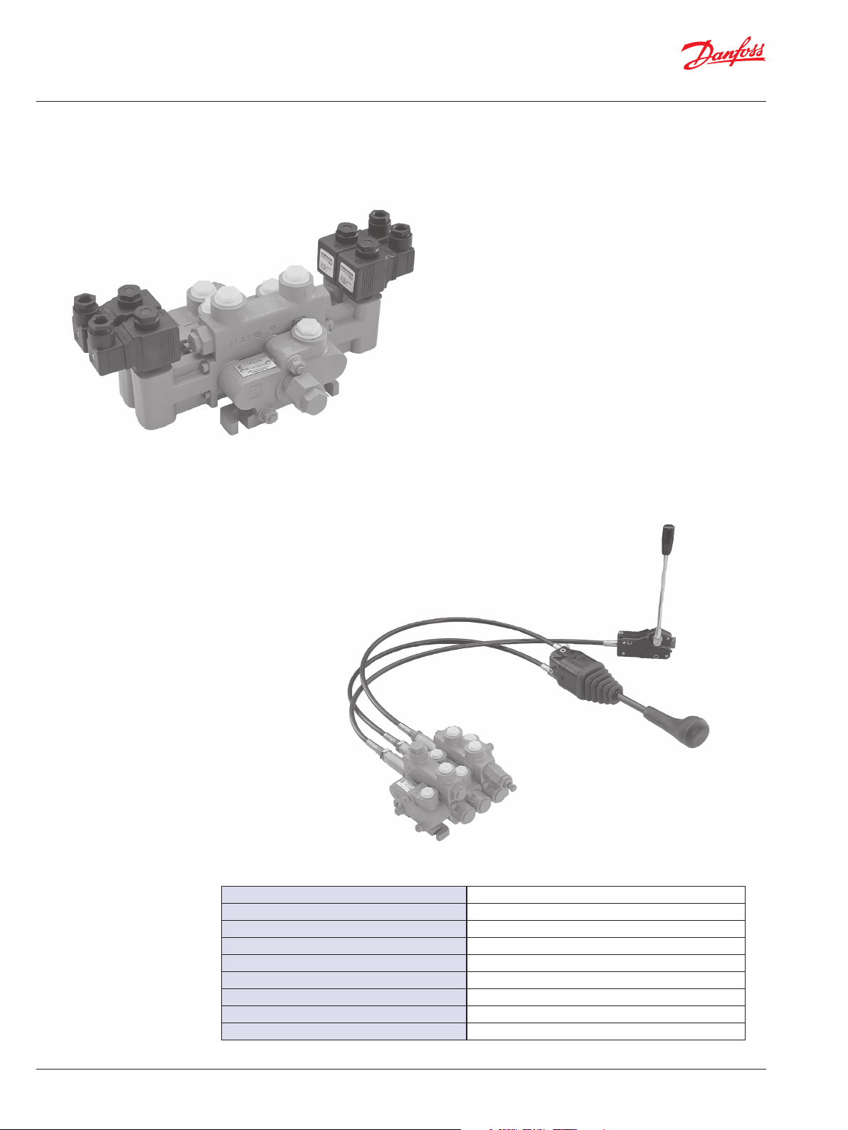
• Handles and levers
• Mechanical two-axis joystick
• Spool ends
• ElectroHydraulic Control (EHC) on/off solenoid
• Cable control
• Pneumatic pilot control
• Dual spool ends
3 | © Danfoss | March 2016
520L0564 | BC00000105en-US0101
Page 4

Directional Control Valves Technical Information:
Product overview
MODULAR VALVES
Valve
model
CDS-100 100 [26] 1 to 12
CDS-60 60 [16] 1 to 12
20 [5] 40 [11] 60 [16] 80 [21] 100 [26]
l/min [US gal/min]
Number
of Spools
Circuit Page
Parallel
Tandem
Series
Parallel
Tandem
Series
Indicates Maximum Working Pressure Rated At 210 bar [3000 psi]
4 | © Danfoss | March 2016
520L0564 | BC00000105en-US0101
Page 5

Directional Control Valves Technical Information:
Fluids and Filtration
FLUIDS Hydraulic fluid performs three basic functions in a hydraulic system: It transfers energy,
lubricates moving components, and transports heat and contaminants out of the system.
Base stock and additives
Danfoss valves are designed to operate with mineral-based fluids containing oxidation, rust,
and foam inhibitors, compatible with fluoroelastomer seals. Consult your fluid supplier for
information on seal compatibility.
Viscosity
Viscosity is the most important property of a hydraulic fluid. It is a measurement of how the
fluid resists flow. Low viscosity fluids increase internal leakage; high viscosity fluids increase
pressure drop through the valve. Use a fluid that meets the viscosity limits published in this
catalog. For specific requirements, see technical data in each section.
Temperature
Temperature affects a fluid’s viscosity. Higher temperature fluid has lower viscosity.
Operating at excessive temperatures may have other detrimental effects on your hydraulic
fluid. Design your hydraulic system to operate within the specified temperature range.
Specific requirements are published in each section.
For more information
For more information on hydraulic fluid selection refer to Hydraulic Fluids and Lubricants
Technical Information, Danfoss publication 520L0463.
FILTRATION
Effective filtration is critical to a hydraulic system’s performance and working life. Employ
system filtration capable of meeting the published requirements in each valve section. Be
aware that other components in the system may have more stringent requirements. Design
your filtration system to satisfy the requirements of the most sensitive component.
Return line filtration
Return line filtration is generally adequate for Danfoss valves. We recommend a 10 micron
nominal (20 micron absolute) or finer filter. Insure the filter in your system is properly sized
and maintained. To facilitate proper filter maintenance, use a pressure gauge or other
indicator to signal when it is necessary to change the filter. Never allow filter to reach its
bypass condition. Follow the filter manufacturer’s maintenance recommendations.
Cleanliness
Hydraulic system contamination must not exceed the limits published for each valve. Limits
are specified per ISO 4406 (1999). When measuring system contamination, calibrate test
equipment in accordance with the ACFTD method.
For more information
For more information on system filtration, refer to Design Guidelines for hydraulic fluid
cleanliness, Danfoss publication 520L0467.
5 | © Danfoss | March 2016
520L0564 | BC00000105en-US0101
Page 6
Directional Control Valves Technical Information:
CDS 60 and 100
CDS 100
SPECIFICATIONS
6 | © Danfoss | March 2016
CDS 60
Maximum flow (CDS 100) 100 l/min [26.4 US gal/min]
Maximum flow (CDS 60) 60 l/min [15.8 US gal/min]
Work pressure 210 bar [3050 psi]
Maximum pressure 250 bar [3625 psi]
Maximum pressure (outlet section) 40 bar [580 psi]
Temperature range -40º to 80º C [-40 to 176º F]
Recommended fluid type Mineral based hydraulic oil
Recommended viscosity 26-55 mm²/sec (cSt) [123-255 SUS]
Minimum fluid cleanliness (per ISO 4406) 19/16
520L0564 | BC00000105en-US0101
Page 7
12 sections
11 sections
10 sections
Pressure - bar [psi]
Flow - l/min [US gal/min]
100
250
Pressure - bar [psi]
[26]
Flow - l/min [US gal/min]
12 sections
11 sections
10 sections
Pressure - bar [psi]
Directional Control Valves Technical Information:
CDS 60 and 100
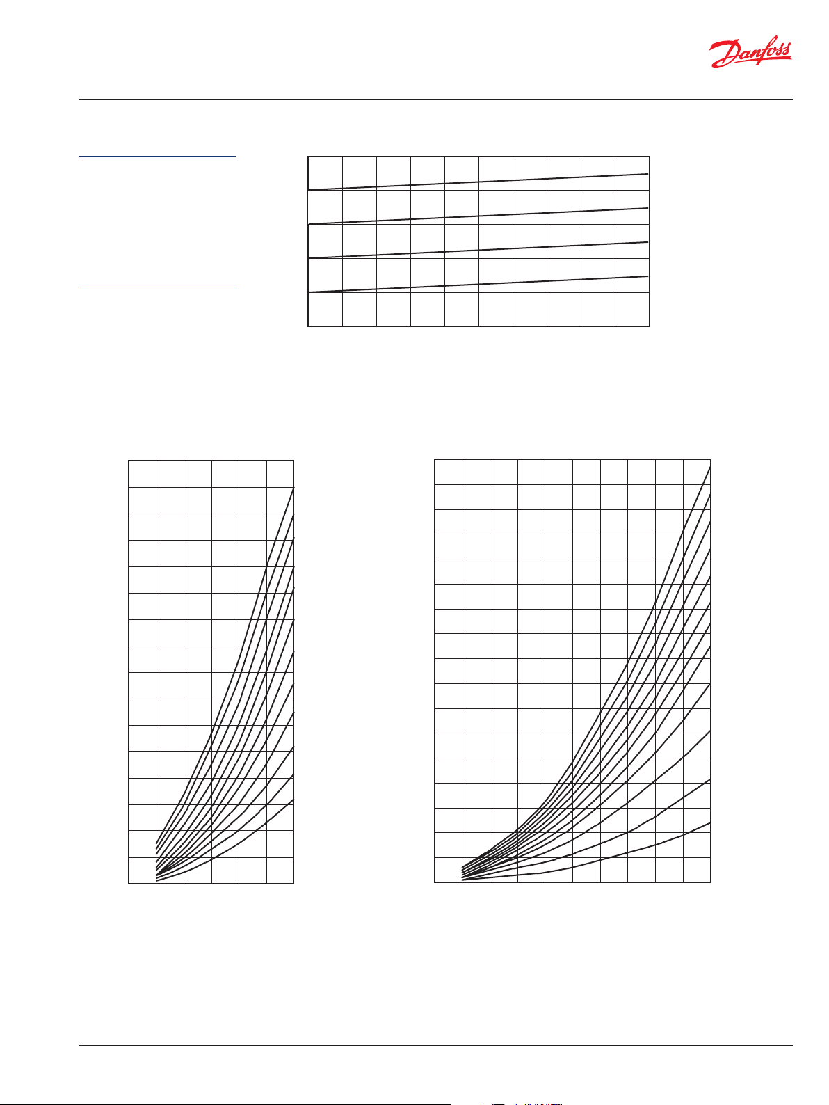
TYPICAL PERFORMANCE
Based on oil temperature
of 45°–50°C [113°–122° F].
Viscosity 32 mm²/sec
(cSt) [151 SUS]. CDS
spool leakage (standard)
at 70 bar [1015 psi],
50°C [122°F], ISO VG46:
10 cm³/min [0.61 in³/min]
16
[232]
14
[203]
12
[174]
10
[145]
[116]
[87]
8
6
Pressure vs. flow curves for main relief valve
[3625]
200
[2900]
150
[2176]
100
[1450]
50
[725]
0
0102030405060708090
[2.6] [5.3] [7.9] [10] [13] [16] [19] [21] [24]
Pressure drop (P-T) CDS 100Pressure drop (P-T) CDS 60
16
[232]
14
[203]
9 sections
8 sections
7 sections
6 sections
5 sections
4 sections
3 sections
12
[174]
10
[145]
[116]
[87]
8
6
9 sections
8 sections
7 sections
6 sections
5 sections
4 sections
3 sections
7 | © Danfoss | March 2016
4
[58]
2
[29]
0
0 10 20 30 40 50 60
[2.6] [5.3] [7.9] [10] [13] [16]
Flow - l/min [US gal/min]
2 sections
1 sections
4
[58]
2
[29]
0
0 10 20 30 40 50 60 70 80 90 100
[2.6] [5.3] [7.9] [10] [13] [16] [19] [21] [24] [26]
520L0564 | BC00000105en-US0101
2 sections
1 sections
Page 8
Directional Control Valves Technical Information:
CDS 60 and 100
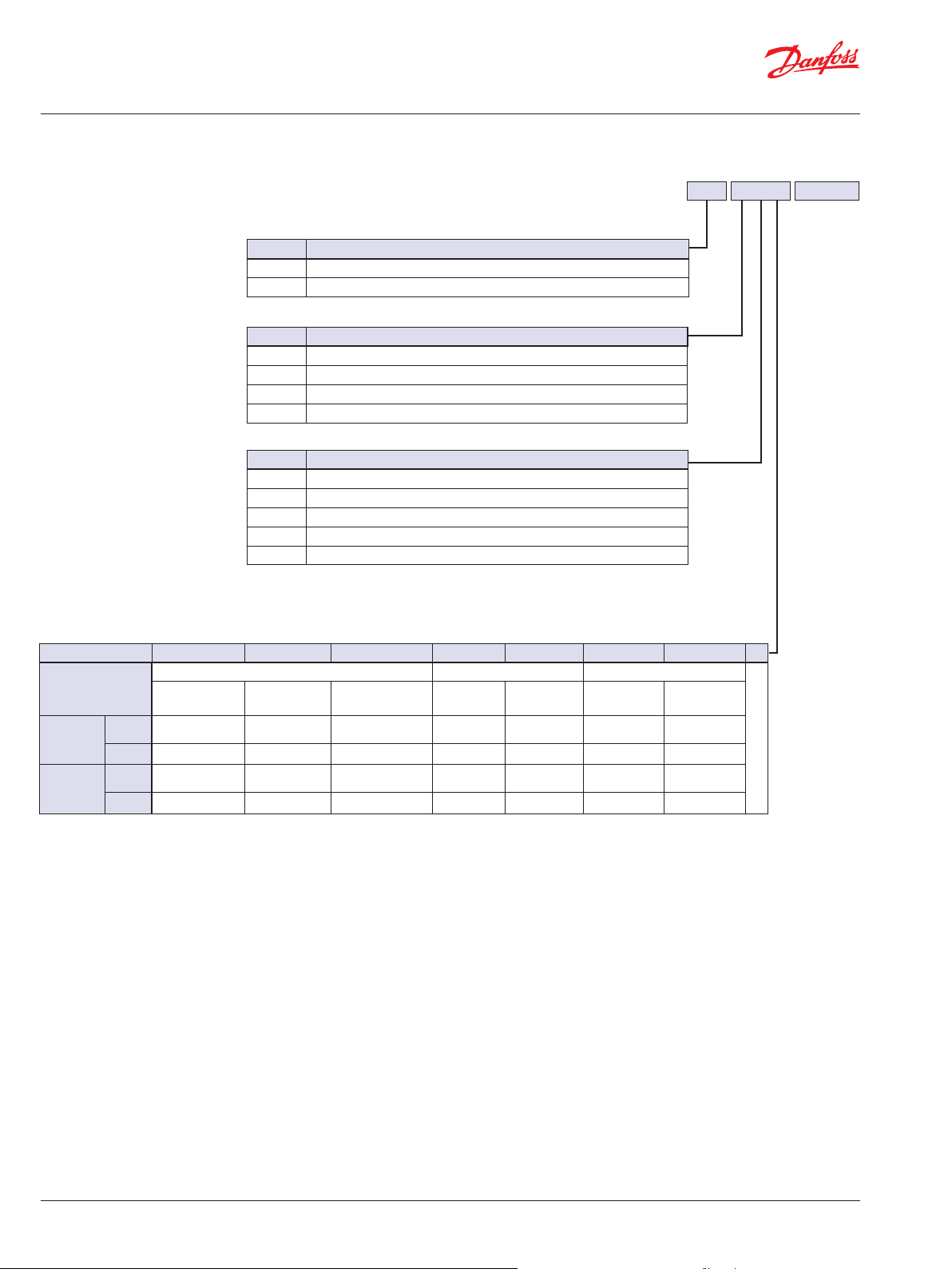
INLET COVERS ORDER
CODE
Inlet covers order code (example)
E60 A C 2 140/40*
Models
Code Description
E100 CDS100
E60 CDS60
Port locations
Code Description
A Top port
B Side port, top port plugged
C Top port, with side gauge port (9/16-18UNF)
D Top inlet and outlet ports (use H, I, J on outlet)
Main relief valves
Code Description
A No valve, with plastic plug
B No valve, with special plug
C Valve, with direct valve and external adjustment
D Valve, with direct valve and internal adjustment
E* Valve, pilot operated and external adjustment
* on request
Port types
Code 1 2 3 4 5 7 8 X
SAE - ORB BSP - Parallel Metric - ISO 6149
Threads
Model
CDS100
Model
CDS60
Inlet
outlet
Section
Inlet
outlet
Section
#8
3/4 -16UNF
m m
m m m m
#10
7/8 -14UNF
m m
m m
#12
1 1/16-12UNF
3/8 -19 1/2 -14 M18x1.5 M22x1.5
m
m
available
m on request
Special porting, specify
8 | © Danfoss | March 2016
520L0564 | BC00000105en-US0101
Page 9

Directional Control Valves Technical Information:
CDS 60 and 100
INLET PORTING AND
RELIEF VALVE OPTIONS
E100 inlet cover
Port location
D*
Top inlet and outlet (use with H,I,J,and L outlet covers)
A Top inlet
C Top inlet,gauge port side (9/16 - 18 UNF)
A
Shipping Plug
B Side inlet
(top plugged)
B
h1 in
PT
[0.43]
Inlet covers order code (example)
E60 A C 2 140/40*
11
E60 inlet cover
C
D
E*
Drawing
h 1 in h 7/8 h 7/16
67
[2.64]
max
h1 in
47
[1.85]
9 | © Danfoss | March 2016
P101 798
* On request
mm [in]
520L0564 | BC00000105en-US0101
Page 10

Directional Control Valves Technical Information:
CDS 60 and 100
OUTLET COVERS ORDER
CODE
Outlet covers order code (example)
S60
Models
Code Description
S100 CDS 100
S60 CDS 60
Ports
Code Description
A Top outlet
B Side outlet, top plugged
C Side outlet for power beyond (top to tank)
D Top outlet (with closed bypass)
E Top outlet (for electrical control)
F Top outlet (for electrical control, with power beyond)
G Side outlet (for electrical control, top plugged)
H* Top plugged
I* Top plugged, use with power beyond
J* Top plugged for electrical control
L* Top plugged for electrical control, use with power beyond
* On request ( use D on inlet)
Port types
Code 1 2 3 4 5 7 8 X
SAE - ORB BSP - Parallel Metric - ISO 6149
Threads
Model
CDS100
Model
CDS60
outlet
outlet
#8
3/4 -16UNF
m m m m
#10
7/8 -14UNF
m m
#12
1 1/16-12UNF
3/8 -19 1/2 -14 M18x1.5 M22x1.5
available
m on request
A 2
specify
Special porting,
10 | © Danfoss | March 2016
520L0564 | BC00000105en-US0101
Page 11

** On request
Directional Control Valves Technical Information:
CDS 60 and 100
OUTLET PORTING AND
PLUG OPTIONS
S100 outlet cover
H** Top plugged
A
Top outlet (side plugged)
C
I
D*
Bypass
Pressure
Outlet
Bypass
Pressure
Outlet
Bypass
Pressure
Outlet
Outlet covers order code (example)
A 2
S60
T
PB
T
PB
T
30
[1.18]
25
[0.98]
B Side outlet (top plugged)
S60 outlet cover
mm [in]
P101 799E
E
F
L
G
Bypass
Pressure
Outlet
J
Bypass
Pressure
Outlet
Bypass
Pressure
Outlet
Bypass
Pressure
Outlet
Bypass
Pressure
Outlet
T
T
T
PB
T
PB
T
PB
*Typically used for high pressure standby.
CDS 60
CDS 100
CDS 60
CDS 100
30.5
[1.20]
32
[1.25]
30.5
[1.20]
32
[1.25]
30
[1.18]
11 | © Danfoss | March 2016
520L0564 | BC00000105en-US0101
Page 12

Directional Control Valves Technical Information:
Parallel (no priority)
Tandem (priority)
Series (no priority)
Actuator mounted on A port side
Actuator mounted on B port side
Electrical A and B (use L centering type)
CDS 60 and 100
WORK SECTION ORDER CODE
Model
A100 CDS 100 body for supporting valves
B100 CDS 100 normal body (no valves)
A60 CDS 60 body for supporting valves
B60 CDS 60 normal body (no valves)
Circuit types, page 15
1
2*
3*
Spool types, page 16
A 4-way, closed center
B 4-way, open center
C 4-way, closed center, port A plugged
D 4-way, closed center, port B plugged
E 3-way, closed center, port A plugged
F 3-way, closed center, port B plugged
G 4-way, open center, port A plugged
H 4-way, open center, port B plugged
I Float-spool in (use centering option J )
J Float-spool out (use centering option J)
Spool actuation, pages 17–18
A No extension
B Female spool end + Clevis
C Male spool end + Tang
D With support (no lever)
E With lever
F Pneumatic (use centering option A)
G Cable with lever
H Cable with joystick (use A for the adjacent body)
I/M With mechanical joystick (use A for the adjacent body)
J Electrical
R Female spool end
S Male spool end
T Female Spool end with adjust
Spool actuation mounting side, page 20
1
2
3
* On request
Work section order code (example)
1 A E 2 A 1 A B 140/40*A100A100
See cabling and
electrical options,
page 22.
12 | © Danfoss | March 2016
520L0564 | BC00000105en-US0101
Page 13

Directional Control Valves Technical Information:
CDS 60 and 100
WORK SECTION ORDER CODE (continued)
Work section order code (example)
1 A E 2 A 1 A B 140/40*A100A100
Spool centering and detents, page 20-21
A Spring centered
B 3 position detent
C Spring centered, detent in A
D Spring centered, detent in B
E Spring centered, detent in A and B
F Spring centered, hydraulic kickout
H Spring centered, female extension
I Spring centered, male extension
J Spring centered, detent in float: use for floatation spool
L Spring centered, use for electrical command
N 2-position detent, spool in
O 2-position detent, spool out
P* With switch, activates spool in
Q* With switch, activates spool in and out
R* With switch, activates two motors
* on request
Port types
Code 1 2 3 4 5 7 8 X
SAE - ORB BSP - Parallel Metric - ISO 6149
Threads
Model
CDS100
Model
CDS60
Section
Section
Auxiliary valves, page 22-23
A Plug
B Direct relief with external adjustment (except electrical actuation)
C Direct relief with internal adjustment
D Pilot check valve
E* Flow control valve (Except electrical actuation)
F Anti-cavitation
G
I Direct relief with anti-cavitation and internal adjustment (electrical only)
J Plug, for 3-way spools
K Plug, for valves D and E
For valves B, C, G, and I, specify pressure and flow
Example: B(140/40) Pressure 140 bar flow 40 l/min
* On request
Direct relief with anti-cavitation and external adjustment
(except electrical actuation)
#8
3/4 -16UNF
m m m
#10
7/8 -14UNF
m m
#12
1 1/16-12UNF
3/8 -19 1/2 -14 M18x1.5 M22x1.5
Work port side A
Work port side B
available
m on request
specify
Special porting,
13 | © Danfoss | March 2016
520L0564 | BC00000105en-US0101
Page 14

Directional Control Valves Technical Information:
ACTINGS AND CENTERING COMBINATIONS AVAILABLE
CDS 60 and 100
Actings
A B C D E F G H I/M J
A
B
C
D
E
•••••••••
••••••••
••••••••
••••••••
••••••••
F
G
H
I
Centerings
J
L
N
O
P
Q
R
••••••••
•••••••••
•••••••
•
•••••••••
••••••••
••••••••
••••••••
•••••••••
•••••••••
•••••••••
•
14 | © Danfoss | March 2016
available
520L0564 | BC00000105en-US0101
Page 15

Directional Control Valves Technical Information:
PABABT
OutletWork sectionsInlet
TTP A
A
B
B
Inlet and Outlet
Work Sections
Outlet
PABABT
OutletWork sectionsInlet
CDS 60 and 100
CIRCUIT TYPES
1 Parallel circuit (no priority)
When two or more sections operate simultaneously, flow favors the lowest pressure.
2 Tandem circuit (priority)*
Work section order code (example)
1 A E 2 A 1 A B 140/40*A100A100
Bypass
Pressure
P101 696
When two or more sections operate simultaneously, only the section closest to the inlet receives flow.
3 Series circuit (no priority)*
Bypass
P101 697
Pressure
Bypass
P101 698
15 | © Danfoss | March 2016
When two or more sections operate simultaneously, the section closest to the inlet receives flow. Return flow
feeds the sections downstream.
* on request
520L0564 | BC00000105en-US0101
Page 16

Bypass core
Directional Control Valves Technical Information:
CDS 60 and 100
SPOOL TYPES
Standard central body
Tank (x2)
Pump load check
standard on all bodies
P101 743
Pressure core
Work section order code (example)
1 A E 2 A 1 A B 140/40*A100A100
Ref. Description Symbol
A
B
C
D
E
4-way closed center
4-way open center
4-way closed center
port A plugged
4-way closed center
port B plugged
3-way closed center
port A plugged
AB
P
T
AB
T
P
AB
P
T
AB
P
T
AB
Central body for use with auxiliary valves
Pump load check
standard on all bodies
F
G
H
I
J
3-way closed center
port B plugged
4-way open center
port A plugged
4-way open center
port B plugged
Float spool in (inner
inverter)
Float spool out (outer
inverter)
P
AB
P
AB
P
AB
P
AB
T
P
T
T
T
T
AB
16 | © Danfoss | March 2016
520L0564 | BC00000105en-US0101
Page 17

Directional Control Valves Technical Information:
50
66
[0.31]
30
[0.31]
30
8
CDS 60 and 100
ACTUATION OPTIONS
A Without spool end
C Male spool end (tang)
[0.31]
6.5
[0.26]
M8 x1.25
M10 x 1.5
CDS 100
CDS 60
[1.18]
34
[1.34]
CDS 60
CDS 100
Work section order code (example)
1 A E 2 A 1 A B 140/40*A100A100
B Female spool end (clevis)
F
D With support
[1.18]
34
[1.34]
ø 8
CDS 60
CDS 100
M10x1.5
CDS 60
CDS 100
[2.60]
70
[2.76]
6.4
[0.25]
8.4
[0.33]
CDS 60
CDS 100
E With lever
8.3
[0.33]
M
ø 8
113
[4.45]
15º
15º
213
[8.39]
F Pneumatic
[1.97]
(2x)
1/8" NPT
Minimum air pressure CDS 60: 5 bar [73 psi]
Minimum air pressure CDS 100: 8 bar [116 psi]
Maximum air pressure: 12 bar [174 psi]
mm [in]
17 | © Danfoss | March 2016
* Default relief setting if not specified
520L0564 | BC00000105en-US0101
Page 18

C2
A
*
Directional Control Valves Technical Information:
CDS 60 and 100
ACTUATION OPTIONS (continued)
97
[3.82]
157
[6.18]
ø 6
[0.24]
30º
118.5
[4.66]
30º
[1.02]
[0.28]
[0.28]
40
[1.57]
50
[1.97]
26
7
7
50
[1.97]
280
[11.02]
48
[1.89]
Work section order code (example)
1 A E 2 A 1 A B 140/40*A100A100
H Cable with joystick**G Cable with lever**
395
25°
[15.55]
Ø
70
[2.76]
25°
I/M Mechanical joystick
J Electrical**
Flying leads
12VCC
90
[3.54]
(Ref.)
1.5m
24VC
[5 ft]
83
[3.27]
(Ref.)
2
1
307
[12.09]
15º
2
15º
117
[4.61]
(Ref.)
DIN43650
1
**See cabling and electrical
options, page 20.
I
1
2
M
2
1
Standard sections cannot be
converted to electrical due to
12VCC
4VCC
Manual override
P101781a
96
[3.78]
(Ref.)
internal pilot.
Minimum pilot pressure to
actuate: 35 bar [500 psi]
mm [in]
18 | © Danfoss | March 2016
520L0564 | BC00000105en-US0101
Page 19

Directional Control Valves Technical Information:
CDS 60 and 100
CABLING AND ELECTRICAL
OPTIONS FOR ACTUATOR
TYPES G, H, AND J
Work section order code (example)
1 A E 2 A 1 A B 140/40*A100A100
G: Flexible cable and lock options for spool control lever
A B C
Lever lock options Without lock Lock in A and/or B Lock in central position
Standard cables 100 - 125 - 150 - 175 - 200- 250 - 275- 300 - 325 - 350 - 400 - 450 - 500 cm (other: consult)
Example: how to order
A60 - 1AG2A1 - AB - A100 - 140/40 (lever without lock, 100 cm cable)
H: Flexible cable and handle options controls for joystick
A
Joystick handle options Without switches
Standard cables 100 - 125 - 150 - 175 - 200 - 250 - 275 - 300 - 325 - 350 - 400 - 450 - 500 cm (other: consult)
Example: how to order
A60 - 1AH2A1 - AB - A100 - 140/40 (handle without switches, 100 cm cable)
J: Electrical spool voltage and termination options
Voltage A 12 VDC -lead wires B 24 VDC - lead wires E
Example: how to order
A60 - 1AJ3L1 - AC - A 140/40 (12 VDC coil with lead wires)
Force requirements
kgf [lbf] CDS 60 CDS 100
Push/pull
min.
Max. tension 250 [551] 250 [551]
2 [4.4] 3.5 [7.7]
ACTUATION MOUNTING
SIDE
B
B
T
A
P
A
12 VDC - DIN 43650
conn.
24 VDC - DIN 43650
F
conn.
Electrical specifications
Voltage Amperage (A) Resistance (Ω)
12 VDC 1.75 6.85
24 VDC 0.88 27
Power: 21 W
2 Actuation on B port side (LH inlet shown)1 Actuation on A port side (RH inlet shown)
CDS100 CDS60
AA
BPBT
A
BPB
A
T
19 | © Danfoss | March 2016
CDS100
P101 822
CDS60
P101 796
520L0564 | BC00000105en-US0101
Page 20

Directional Control Valves Technical Information:
CDS 60 and 100
SPOOL CENTERING AND DETENT OPTIONS
3 position detent
Spring centered
A
32
CDS 60
[1.25]
40
CDS 100
[1.57]
Spring force
CDS 60: 145-155 N [32-35 lbf]
CDS 100: 240-245 N [54-55 lbf]
Spring center out,detent in
D
56
CDS 60
[2.20]
73
CDS 100
[2.87]
B
Spring centered,detent in A and B
E
56
[2.20]
73
[2.87]
32
[1.25]
40
[1.57]
CDS 60
CDS 100
CDS 60
CDS 100
Work section order code (example)
1 A E 2 A 1 A B 140/40*A100A100
Spring center in,detent out
C
56
CDS 60
[2.20]
73
CDS 100
[2.87]
Spring centered,h
F
92
CDS 60
[3.62]
96
CDS 100
[3.78]
ydraulic kickout
Spring centered,female extension
H
88±5
CDS 60
[3.46±0.2]
93 ±5
CDS 100
[3.66± 0.2]
8
Ø
[0.31]
CDS 60
6.4
[0.251]
8.4
[0.331]
CDS 100
F
Spring centered,floatation spool
J
20.5
[0.81]
65
[2.56]
78
[3.07]
CDS 60
CDS 100
Spring centered,male extension
I
88±5
CDS 60
[3.46±0.2]
93 ±5
CDS 100
[3.66± 0.2]
8
Ø
[0.31]
8.3
[0.33]
10
[0.39]
12.5
[0.49]
CDS 60
CDS 100
20
[0.79]
Note:Float body section required
82
[3.23]
101
[3.97]
CDS 60
CDS 100
Note:Unlock body section
required for use with hydraulic
unlock kit.
20 | © Danfoss | March 2016
Float in
Float out
mm [in]
* Default relief setting if not specified
520L0564 | BC00000105en-US0101
Page 21

Directional Control Valves Technical Information:
*on request
P106 330E
CDS 60 and 100
SPOOL CENTERING AND DETENT OPTIONS (continued)
Two-position detent:
N
neutral and spool in
Spring centered with switch:
P*
activates on spool in
32
CDS 60
[1.26]
40
CDS 60
6.5 [0.26]
8.0 [0.32]
CDS 100
[1.57]
CDS 100
Spring centered with switch:
Q*
activates on spool in and out
CDS 60
CDS 100
CDS 60
6.5 [0.26]
8.0 [0.32]
CDS 100
32
[1.26]
40
[1.57]
6.5 [0.26]
8.0 [0.32]
CDS 60
CDS 100
32
[1.26]
40
[1.57]
CDS 60
CDS 100
Work section order code (example)
1 A E 2 A 1 A B 140/40*A100A100
Two-position detent:
O
neutral and spool out
Spring centered with switch:
R*
activates two motors
32
[1.26]
40
[1.57]
CDS 60
CDS 100
21 | © Danfoss | March 2016
520L0564 | BC00000105en-US0101
Page 22

AKJ
Directional Control Valves Technical Information:
CDS 60 and 100
AUXILIARY VALVES
Central body for use with auxiliary valves
For3ways spools.
TP
Work section order code (example)
1 A E 2 A 1 A B 140/40*A100A100
11
[0.43]
For valves B,C, F, G, and I
B
C
D
11
[0.43]
1 in1 in
ForvalvesDandE.
1 in 11/16 7/16
67
[2.64]
Max
1 in
47
Standard
[1.85]
29
Short version
[1.14]
(use with electrical
actuation)
1 in
10
[0.39]
1 in
mm [in]
P101 746E
E*
F
G
I
16
[0.63]
7/8
1 in
5/8
1 in
[1.14]
CDS 60
Knob
29
62
[2.44]
Max
1 in
12
[0.47]
1 in 11/16 7/16
70
[2.76]
Max
22 | © Danfoss | March 2016
520L0564 | BC00000105en-US0101
Page 23

Directional Control Valves Technical Information:
10
152
[0.59]
Y
[1.49]
CDS 60 and 100
AUXILIARY VALVES (continued)
Auxiliary valves compatibility
A B C D E F G I J K
A
B
C
D
E
F
G
I
J
K
— — —
— — — —
—
— — —
— Not compatible
Compatible (EXCEPT electrical) Compatible (ONLY electrical)
DIMENSIONS CDS 100
30
[1.18]
46
[1.81]
—
46
[1.81]
Work section order code (example)
1 A E 2 A 1 A B 140/40*A100A100
— —
— —
— —
— —
— —
— —
— —
Compatible
— — — — —
— — — —
— — — —
—
—
—
[5.98]
82
[3.23]
— —
— —
—
—
—
—
—
38
100
[3.94]
25
[0.98]
X
25
[0.98]
15
127
[5.00]
Reference dimensions
AA
BPBT
44.5
[0.39]
R
t 27 N•m
5.5
[0.22]
20 lbf•ft
Number of
sections
X Y
1 95 [3.74] 137 [5.39]
2 139 [5.47] 181 [7.13]
3 184 [7.24] 226 [8.89]
4 229 [9.02] 270 [10.63]
5 273 [10.75] 314 [12.36]
6 318 [12.52] 359 [14.13]
7 362 [14.25] 403 [15.87]
8 406 [15.98] 448 [17.64]
9 451 [17.76] 492 [19.37]
10 495 [19.49] 537 [21.14]
11 540 [21.26] 581 [22.87]
12 584 [22.99] 626 [24.65]
mm [in]
23 | © Danfoss | March 2016
520L0564 | BC00000105en-US0101
Page 24

[1.02]
120
Y
Directional Control Valves Technical Information:
DIMENSIONS CDS 60
24
[0.94]
32
[1.26]
38
[1.50]
38
[1.50]
CDS 60 and 100
82
[3.23]
[4.72]
56 74*
[2.20] [2.91]
18
[0.71]
14
[0.55]
18
[0.71]
X
Reference dimensions
Number of
sections
98
[3.86]
X Y
1 72 [2.83] 112 [4.41]
2 108 [4.25] 148 [5.83]
3 144 [5.67] 184 [7.42]
A
A
26
P
B
B
36
[1.42]
T
P101 795
r.
[0.51]
4.5
[0.18]
13
28.5
[1.12]
t 18 N•m
13 lbf•ft
4 180 [7.09] 220 [8.66]
5 216 [8.50] 256 [10.08]
6 252 [9.92] 292 [11.50]
7 288 [11.34] 328 [12.91]
8 324 [12.76] 364 [14.33]
9 360 [14.17] 400 [15.75]
10 396 [15.59] 436 [17.17]
11 432 [17.01] 472 [18.58]
12 468 [18.43] 508 [20.00]
Mounting requirements
24 | © Danfoss | March 2016
A
Flatness 0.5-0.8 [0.02 to 0.03] max Flatness 0.5-0.8 [0.02 to 0.03] max
B
77 78
P106 331E
520L0564 | BC00000105en-US0101
Page 25

Directional Control Valves Technical Information:
CDS60 AND CDS100 SPECIFICATION WORKSHEET
Appendix 1 - Order forms
“B” Port
Side Flow (l/
min)
Threads
Options
Control No.
Subsidiary/Dealer
Model Model Size Ports
None
Black Primer
Black Paint
“B” Port
Side
“A” Port Side
“A” Port Side
Pressure
Cable
Length
Cable or
Electrical
Aux Valves
Aux Valves
Threads
Pressure
(Bar)
Flow (l/min)
(Bar)
Centi-
meters
Control
Options
“B”
“A”
Directional Control Valves CDS60 and CDS100
Specification Order Form
Customer Application
25 | © Danfoss | March 2016
Inlet Section Paint Outlet Section
Port Side
Flow
Pressure
Threads Port Side
Main
relief
Port
Size
Side
Model Model
Center
Type
Spool
Control
Side
Spool
Controls
Spool
Types
Valves
Work Sections
Circuit
Type
Model
Size
Model
Work
section
1st
2nd
3rd
4th
5th
6th
7th
8th
9th
10th
11th
12th
Number of sections =
Price US $: Delivery: Date:
520L0564 | BC00000105en-US0101
Page 26

OUR PRODUCTS
Hydrostatic transmissions
Danfoss Mobile Power and Control Systems
– Market Leaders Worldwide
Danfoss is a comprehensive supplier providing complete systems
to the global mobile market.
Hydraulic power steering
Electric power steering
Electrohydraulic power steering
Closed and open circuit axial piston
pumps and motors
Gear pumps and motors
Bent axis motors
Orbital motors
Transit mixer drives
Planetary compact gears
Proportional valves
Directional spool valves
Cartridge valves
Hydraulic integrated circuits
Hydrostatic transaxles
Integrated systems
Fan drive systems
Danfoss serves markets such as agriculture, construction, road
building, material handling, municipal, forestry, turf care, and many
others.
We offer our customers optimum solutions for their needs and
develop new products and systems in close cooperation and
partner ship with them.
Danfoss specializes in integrating a full range of system
components to provide vehicle designers with the most advanced
total system design.
Danfoss provides comprehensive worldwide service for its
products through an extensive network of Global Service Partners
strategically located in all parts of the world.
Local address:
Electrohydraulics
Microcontrollers and software
Electric motors and inverters
Joysticks and control handles
Displays
Sensors
Danfoss can accept no responsibility for possible errors in catalogues, brochures and other printed material. Danfoss reserves the right to alter its products without notice.
This also applies to products already on order provided that such alterations can be made without subsequential changes being necessary in specifications already agreed.
All trademarks in this material are property of the respective companies. Danfoss and the Danfoss logotype are registered trademarks of Danfoss A/S. All rights reserved.
26 | © Danfoss | March 2016
Danfoss (US) Company
2800 East 13th Street
Ames, IA 50010, USA
Phone: +1 515 239-6000
Fax: +1 515 239-6618
Danfoss GmbH & Co. OHG
Postfach 2460, D-24531 Neumünster
Krokamp 35, D-24539 Neumünster, Germany
Phone: +49 4321 871-0
Fax: +49 4321 871 122
Danfoss ApS
DK-6430 Nordborg, Denmark
Phone: +45 7488 4444
Fax: +45 7488 4400
Danfoss-Daikin LTD
Sannomiya Grand Bldg. 8F
2-2-21 Isogami-dori, Chuo-ku
Kobe, Hyogo 651-0086, Japan
Phone: +81 78 231 5001
Fax: +81 78 231 5004
520L0564 | BC00000105en-US0101
 Loading...