

Page 1
Page 2

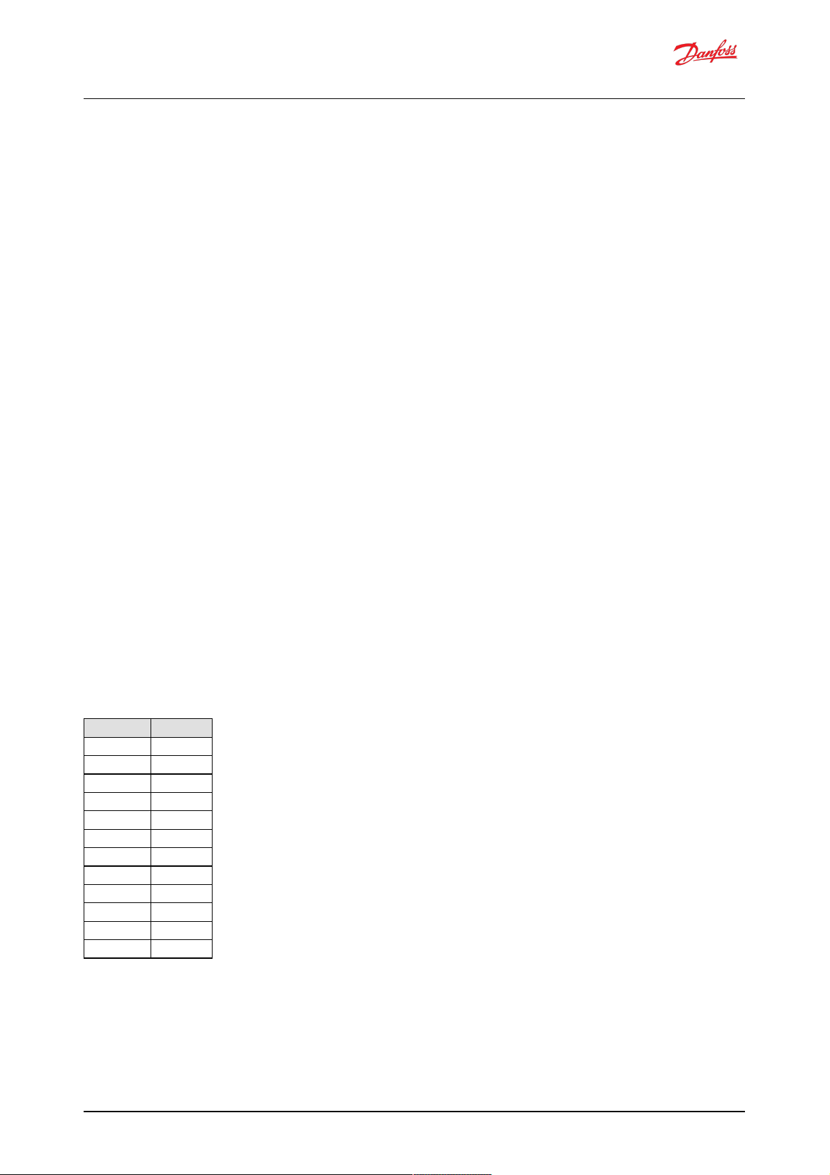
Revision history
Date Chan ged Rev
February 2022 Corrected small errors in sections 9.3 and 9.5.1.4.2 0102
August 2021 First edition: software release 2.7.1 0101
Software Manual
Digital Displacement® Pump Software Version 2.7.1
2 | © Danfoss | Fe bruary 2022 BC404560709540en-000102
Page 3

Contents
1 Rele ase notes
1.1 Ve rsion 2.7.1
1.2 Ve rsion 2.6.3 (originally labeled 2.63)
1.3 Ve rsion 2.5.1 (originally labeled 2.51)
2 Known issues
2.1 CAN Bus Off error after turning on a DPC12 (193548)
2.1.1 Description
2.1.2 Solutions
2.2 J1939 unused reference s req uire valid value (369615)
2.2.1 Description
2.2.2 Solutions
2.3 Not all e rror counters cleared by RESET_ERR_CNTR_CMD (338706)
2.3.1 Description
2.3.2 Solutions
2.4 PLUS+1® parameter value cannot be changed if its source is not set to 1 (346303)
2.4.1 Description
2.4.2 Solutions
2.5 Solenoid fault test fails for cylinder A1 (354599)
2.5.1 Description
2.5.2 Solutions
2.6 Pressure sensor invalid low error w ith sensor connec ted (361396)
2.6.1 Description
2.6.2 Solutions
2.7 Software update fails when using multiple CAN bus devices (400960)
2.7.1 Description
2.7.2 Solutions
2.8 Tw o CG150 gatew ays causes communications error (404422)
2.8.1 Description
2.8.2 Solutions
3 Configuring a new controller
3.1 Use of a CAN Bus
3.2 Control config uration required
3.3 Control loop gains
3.4 PLUS+1® Service Tool
3.5 Backup parameters
4 Commissioning mod e
4.1 Entering and exiting commissioning mode
4.2 Commissioning actions
4.2.1 Fire
4.2.2 Pump
4.2.3 Raw displacement
4.2.4 Coil numbe rs
5 Control configuration
5.1 Use case s
5.1.1 Single-service software
5.1.2 Two-service software
6 Two-service ope ration
6.1 Se rvice independence
6.2 Se rvice sw itching
7 Parame ters
7.1 Communication parameters
7.2 Pump setting parame ters
7.3 Pump and controller status parameters
7.4 Se rvice 1 parameters
7.4.1 Control mode paramete rs
7.4.2 Control reference p arameters
7.4.3 Limits parameters
7.4.4 Control loop gain parameters
Software Manual
Digital Displacement® Pump Software Version 2.7.1
3 | © Danfoss | Fe bruary 2022 BC404560709540en-000102
Page 4

7.4.5 Service status parameters
7.5 Se rvice 2 parameters
7.5.1 Control mode paramete rs
7.5.2 Control reference p arameters
7.5.3 Limits parameters
7.5.4 Control loop gain parameters
7.5.5 Service status parameters
7.6 Other parameters
7.7 Commissioning mode parameters
8 Errors
8.1 Error handler states
8.2 Error list
8.3 Diagnosing faults
8.3.1 Diag nostic LED
9 J1939 CAN p rotocol
9.1 Ad dre ss scheme
9.2 PGN priorities
9.3 SLOTs
9.4 Diagnostic messag es
9.4.1 DM1 PGN - active diagnostic trouble codes
9.4.1.1 Message information
9.4.1.2 Message d ata
9.4.1.3 DM1 e xample scenarios
9.4.2 DM2 PGN - pre viously active d iagnostics trouble cod es
9.4.2.1 Message information
9.4.2.2 Message d ata
9.4.2.3 DM2 e xample scenarios
9.4.3 DM3 PGN - diag nostics data clear of previously active DTCs
9.4.3.1 Message information
9.4.3.2 DM3 e xample scenarios
9.4.4 DM11 PGN - diagnostics data clear of active DTCs
9.4.4.1 Message information
9.4.4.2 DM11 example scenarios
9.4.5 DM13 PGN - ignore all info and w arning errors until DM13 is rece ived
9.4.5.1 Message information
9.4.5.2 Message d ata
9.4.5.3 DM13 example scenarios
9.4.6 Request PGN
9.4.6.1 Message information
9.4.6.2 Message d ata
9.4.7 Acknowledgment PGN
9.4.7.1 Message information
9.4.7.2 Message d ata
9.5 M anufacturer spe cific PGNs
9.5.1 Control PGNs
9.5.1.1 Pump setup A
9.5.1.2 Displacement reference A
9.5.1.3 Pressure reference A
9.5.1.4 Pressure margin reference A
9.5.1.5 Torque limit A
9.5.1.6 Flow limit A
9.5.1.7 Power limit A
9.5.2 Status PGNs
9.5.2.1 Pump info A
9.5.2.2 Service 1 status
9.5.2.3 Service 2 status
10 Updating software on the controller
11 Reference s
Software Manual
Digital Displacement® Pump Software Version 2.7.1
4 | © Danfoss | Fe bruary 2022 BC404560709540en-000102
Page 5

1 Release notes
1.1 Version 2.7.1
Reorganised J1939 protocol
Changed PGN framing to conform to Danfoss product compatibility standard
Changed scaling for SPNs to use standard SLOTs w here possible
Added J1939 address claim procedure support
New parame ter for controller instance
New errors for address claim failures
Improved PLUS+1® Se rvice Tool info block details
Service switching configuration can be set from PLUS+1® (as well as J1939)
Added parameter to read FPGA version
Added additional supp orted use cases
Sing le-service
Displacement control by PLUS+1®
Displacement control by PLUS+1® with torque limit
Two-service
Displacement control by PLUS+1®
Displacement control by PLUS+1® with torque limit
Industrial p ressure control by J1939 with flow limit
Industrial p ressure control by J1939 with flow limit and PLUS+1® service configuration
Industrial p ressure control by PLUS+1® w ith flow limit
Load-sense pressure control by J1939 with torq ue limit
Load-sense pressure control by PLUS+1® w ith torque limit
Mixed disp lacement/load-sense by J1939
1.2 Version 2.6.3 (originally labeled 2.63)
Added build for tw o-service pumps (ML)
Changed layout of control reference and limit parame ters from using enable paramete rs (EN_x) to
sourc e parame ters (x_SRC)
Added additional supp orted single-service use cases
Displacement control by J1939
Displacement control by J1939 with torque limit
Industrial p ressure control by PLUS+1®
Industrial p ressure control by PLUS+1® w ith flow limit
Load sensing pressure control by PLUS+1®
Load sensing pressure control by J1939
Load sensing pressure control by PLUS+1® w ith torque limit
Load sensing pressure control by J1939 with torque limit
1.3 Version 2.5.1 (originally labeled 2.51)
First release for sing le -service pumps (SS)
Software Manual
Digital Displacement® Pump Software Version 2.7.1
5 | © Danfoss | Fe bruary 2022 BC404560709540en-000102
Page 6

2 Known issues
2.1 CAN Bus Off error after turning on a DPC12 (193548)
2.1.1 Description
Othe r d evice s on the bus experience CAN faults which lead s to them declaring a CAN Bus Off error after the
DPC12 controlle r is powered on. This causes the devices to stop communicating with the system until their
faults are cleared.
The issue may also lead to difficulty using the PLUS+1® Service Tool Recover ECU function as controller is
power-cycled during this procedure.
The problem is caused by the power-up behavior of the DPC12 CAN transmitter. When the controlle r is
supplied from a current-limite d power supply, the controller can hit this current limit and brown out multiple
times during the initial pow er-up. On e ach brow nout an erroneous signal is transmitted on the CAN bus.
Multiple b row nouts lead to a high enough error count to trigger the CAN Bus Off error on other connecte d
devices.
2.1.2 Solutions
Use a pow er supply with a higher current limit or turn off soft-start behavior.
A hardware solution w ill be implemented in a future DPC12 controller revision.
2.2 J1939 unused references require valid value (369615)
2.2.1 Description
The M anufacturer specific PGNs use d to send the control references and limits to the DDP096 software
includ e sig nals for seve ral service s w ithin the same messag e. In the case w here the value for one of the
services is not being used (due to the correspond ing source parameter, _SRC, being set to unlimited or
PLUS+1®), the DDP096 softw are d oes not accept the correct value for the unuse d signals. To meet the J1939
stand ard the system controlle r should send a "not used/not req uested " value, however upon receiving this
value the DDP096 softw are w ill ge nerate an "Invalid d ata in J1939 message" error.
2.2.2 Solutions
Send value of zero instead of the "not used/not requested" value. This should b e zero in the physical units of
the message, with the rele vant scaling and offset applied.
This issue will be resolved in an upcoming software release.
2.3 Not all error counters cleared by RESET_ERR_CNTR_CMD (338706)
2.3.1 Description
Whe n using the RESET_ERR_CNTR_CMD parameter or DM 3 PGN - diagnostics data clear of previously active
DTCs to reset the error occurrence counte rs, only the first 29 counters with a value gre ater than zero w ill be
cleare d.
2.3.2 Solutions
Send multiple re quests to clear the error counters b y toggling RESET_ERR_CNTR_CMD or sending the DM 3
message repeatedly. This version of the softw are has 72 occurrence counte rs, so issuing the command three
times w ill cle ar all counters.
This issue will be resolved in an upcoming software release.
Software Manual
Digital Displacement® Pump Software Version 2.7.1
6 | © Danfoss | Fe bruary 2022 BC404560709540en-000102
Page 7

2.4 PLUS+1® parameter value cannot be changed if its source is not set to 1
(346303)
2.4.1 Description
PLUS+1® p arameters w hich are read/w rite or read-only depending on the setting of the corresponding
sourc e parame ter (_SRC) cannot be changed until the source is set to PLUS+1®.
This issue is particularly apparent whe n dow nload ing paramete rs from an XM L file in Service Tool.
2.4.2 Solutions
Ensure that the corresponding source parameter is set to PLUS+1® before writing to the parameter. If
downloading an XML file in Service Tool, arrang e the p arameters so that the source paramete r comes earlie r
in the list than the parameter.
2.5 Solenoid fault test fails for cylinder A1 (354599)
2.5.1 Description
The solenoid fault te st occasionally fails for cylinder A1 in a healthy system. The e rror only occurs on the first
test after pow er-on.
2.5.2 Solutions
Disable the start-up solenoid fault te st by setting EN_STARTUP_SOLENOID_FAULT_TEST to 0.
Run the manual solenoid fault test using EN_MANUAL_SOLENOID_FAULT_TEST twice, disregarding the error
states after the first test.
This issue will be resolved in an upcoming software release.
2.6 Pressure sensor invalid low error with sensor connected (361396)
2.6.1 Description
A p ressure sensor invalid low error can be trig gered at low pressure in an e le ctrically noisy environme nt. The
following errors may be seen:
Service 1 outlet pressure reading below minimum (SPN 520960, FMI 18)
Service 2 outlet pressure reading below minimum (SPN 520961, FMI 18)
Service 1 external load-sense pressure reading below minimum (SPN 521020, FMI 18)
Service 2 external load-sense pressure reading below minimum (SPN 521021, FMI 18)
2.6.2 Solutions
Contact Danfoss for advice.
2.7 Software update fails when using multiple CAN bus devices (400960)
2.7.1 Description
Dow nloading new softw are to the DPC12 controller using the PLUS+1® Se rvice Tool can fail when other CAN
bus devices are communicating on the bus.
2.7.2 Solutions
Disconne ct or power-d own other CAN bus devices on the bus before updating the controller software.
If download failure occurs, follow the above ad vice and use the Recover ECU feature in the PLUS+1® Service
Tool to retry the download.
Software Manual
Digital Displacement® Pump Software Version 2.7.1
7 | © Danfoss | Fe bruary 2022 BC404560709540en-000102
Page 8

2.8 Two CG150 gateways causes communications error (404422)
2.8.1 Description
Whe n two Danfoss CG150-2 CAN/USB inte rface gateway d evice s are present on the DPC12's CAN ne twork
parame ter w rite operations may fail.
2.8.2 Solutions
Ensure only one CG150 device is used on the CAN netw ork conne cted to the DPC12.
Software Manual
Digital Displacement® Pump Software Version 2.7.1
8 | © Danfoss | Fe bruary 2022 BC404560709540en-000102
Page 9

3 Configuring a new controller
The DDP096 is a softw are-driven product and requires initial config uration to operate correctly in a hydraulic
system or vehicle. The follow ing items should be considered when setting up the DPC12 controller for the
first time. Failure to do so may result in the pump being unab le to ope rate reliably.
If you have any issues or require assistance with the initial setup, please contact your Danfoss representative.
3.1 Use of a CAN Bus
The DDP096 softw are is de signed to be setup and monitored using a CAN bus. It is recommended that a
diagnostic connector is available in every installation including a DPC12 controller.
The DDP096 softw are includes an error to detect electrical problems w ith the CAN bus during operation. This
error w ill be triggered in a system where no CAN bus is connected to the controller w hile it is operating. To
prevent the error being triggered and the pump disabled, the IGNORE_EPV_FLAG parameter must be
changed from its default value. See the Communication parame ters and Errors sections for further de tails.
Warning
Parameter IGNORE_EPV_FLAG must be set to 1 if no CAN bus connection is present in operation.
The DPC12 controller must be ab le to be uniquely addressed when using a J1939 CAN bus for control or
monitoring. For this it imp le ments the J1939 ad dress claim proced ure. Details of this procedure should be
understood as add ress claim errors w ill result in the pump being disabled. See the Address scheme and
Errors sections for further details.
Warning
If more than one DPC12 is connected to the CAN bus the controllers must be uniquely ad dressed.
3.2 Control configuration required
The factory default setting for the DPC12 controller sets the control method to a static displacement of zero
output. The DDP096 softw are must be config ured to the control method required b y the hydraulic system or
vehicle. Se e the Control configuration section for more de tails.
3.3 Control loop gains
A control loop w ith tuneable gains is used by the software in pressure control and load -sense control mode s.
These gains must be tuned to match the hydraulic characteristics of the system and the desire d pump
response. It is recommended to undergo training or receive assistance from your Danfoss representative
when doing first start-up of a new hydraulic system operating in either of these mod es to ensure that the
control loop g ains can be tuned for optimal system p erformance and response.
3.4 PLUS+1® Service Tool
The Danfoss PLUS+1® Service Tool is used to configure the DDP096 software. Service Tool pages are available
to make interacting w ith the DDP096 software parameters simple. The Service Tool can be downloaded from
the Danfoss w ebsite . Please contact your Danfoss re presentative for access to the DDP096 Service Tool pages.
3.5 Backup parameters
It is highly advisable to backup the DDP096 software paramete rs once setup is comp le te. In the event of
damage to the DPC12 controller or non-volatile memory corruption the backup parameters can be
downloaded to a new DPC12 controlle r to allow the DDP096 pump to function as desire d. Please contact your
Danfoss rep rese ntative for training on using the PLUS+1® Service Tool to export paramete rs from a DPC12
controller.
Software Manual
Digital Displacement® Pump Software Version 2.7.1
9 | © Danfoss | Fe bruary 2022 BC404560709540en-000102
Page 10

Warning
Danfoss and the PLUS+1® Service Tool do not automatically store copies of DDP096 software parameters.
Backups should be made after the configuration is chang ed.
Software Manual
Digital Displacement® Pump Software Version 2.7.1
10 | © Danfoss | February 2022 BC404560709540en-000102
Page 11

4 Commissioning mode
The DDP096 softw are includes a commissioning mode w hich is used to exercise pumping units when the
pump is not in normal operation. More d etail on commissioning a DDP096 pump and DPC12 in a hydraulic
system is provided in the Digital Displace ment® Pump Gen 1 DDP096 and DPC12 Te chnical Information.
Warning
Some error protection is disabled in commissioning mod e. The use r should e nsure that the system is properly
protected hydraulically (for instance with a pressure relief valve on e ach outlet) and is monitored carefully
throughout.
4.1 Entering and exiting commissioning mode
Commissioning mode is ente red by setting the EN_COMMISS parameter to "enabled" (1) and power cycling
the controller. The DEVICE_MODE paramete r can be used to check that the DDP096 software is in
commissioning mode - the value will be 2 w he n in commissioning mode.
Commissioning mode is left by setting the EN_COMMISS p arameter back to "disabled" (0) and power cycling
the controller.
4.2 Commissioning actions
Five actions are available to the user in commissioning mode:
fire
pump x1
pump x100
raw displacement, service 1
raw displacement, service 2
Each is described in the following sections.
To set up an action:
1. the COMMISS_ACT_TYPE paramete r should b e set to the value corresponding to the p articular action.
2. the COMMISS_VALUE parameter should be set to the required coil number or displacement p erce ntag e.
3. the COMMISS_CMD parame ter should be set to 1 to start the action.
4. the COMMISS_CMD parame ter should be set back to 0 w hen the action is comple te before starting the
next action.
Each action may be disabled due to the current shaft speed or active errors. The DDP096 softw are show s
which actions are allowed via the COMMISS_LEVEL parame ter, w hich has three levels:
0. Internal 24V power supply proble m, inc luding no power to coil supply pins, is indicated by the
ERR_AE_3599_02_LM_OUT24V error b eing active.
1. At least one severe error active (other than ERR_AE_3599_02_LM_OUT24V).
2. No severe errors active.
Whe n an action is requested, the DDP096 software reports the result of the request with the
COMMISS_STATUS parameter. It shows w hether a request was d enied , due to the COMMISS_LEVEL being
low er than that required for the requested command, and whe ther the action is in prog ress. For fire and
pump x1 actions the parameter is set to the in progress value only for a very short time.
4.2.1 Fire
The fire action allows the coil of a p articular pumping unit to be ene rgized. This is intend ed to allow the user
to check for correct w iring to the coil, either by listening for the audible click produced during the
energization or by using a current probe to view the current in the wire to the coil.
COMMISS_ACT_TYPE is 1 for the fire action and the COMMISS_VALUE paramete r selects the coil to be fire d (see
Coil numbers section).
Software Manual
Digital Displacement® Pump Software Version 2.7.1
11 | © Danfoss | February 2022 BC404560709540en-000102
Page 12
The fire action is available whether or not the shaft of the pump is sp inning , and requires the COMMISS_LEVEL
to be 1 or 2.
4.2.2 Pump
The pump action e nergizes the coil of a particular pumping unit at the correct shaft angle for pumping,
allowing the user to check that fluid is displaced by that pumping unit. This can be used in conjunction w ith a
flow meter or pressure sensor/gauge to verify the function of that pumping unit.
The COMMISS_VALUE parameter selects the coil to be fired (see Coil numbers section). A single pumping
stroke can b e requeste d using COMMISS_ACT_TYPE 2 and one hundred pumping strokes can be req uested
using COMMISS_ACT_TYPE 3.
The pump action is only available when the shaft is sp inning and the minimum pumping speed is reached (see
the ERR_AE_520975_17_LM_SHSPD error), and requires COMMISS_LEVEL to be 2.
4.2.3 Raw displacement
The raw displacement action allow s the use r to se t the DDP096 to pump indefinitely at a particular fraction of
its availab le flow.
The COMMISS_VALUE parameter sets the displaceme nt fraction, and is scaled the same way as the
DISP_REF_S1 parameter. COMMISS_ACT_TYPE 4 re que sts flow from service 1, and COMMISS_ACT_TYPE 5
requests flow from service 2 (in two-service DDP096 softw are). For two-service operation the selected service
config uration is always that correspond ing to index 0 of the SERV_CONF_INDEX parame ter (see the Service
sw itching section).
The raw displacement action is only available w hen the shaft is spinning and the minimum pumping speed is
reache d (see the ERR_AE_520975_17_LM_SHSPD error), and req uire s COMMISS_LEVEL to be 2.
4.2.4 Coil numbers
For fire or p ump actions the user must send a particular coil numb er to set the DPC12 coil output w hich is to
be actuated.
The map ping betw een pumping units and coil numbers is shown in the follow ing table. Please refe r to the
Dig ital Disp lacement® Pump Gen 1 DDP096 and DPC12 Technical Information for the physical locations of the
pump ing units within the DDP096 pump.
Pum ping unit Coil nu mber
A1 0
B1 1
C1 2
A2 3
B2 4
C2 5
A3 6
B3 7
C3 8
A4 9
B4 10
C4 11
Software Manual
Digital Displacement® Pump Software Version 2.7.1
12 | © Danfoss | February 2022 BC404560709540en-000102
Page 13
5 Control configuration
The DDP096 softw are is able to operate each service (hydraulic output) in one of se veral configurations to
provide the required control re sponse . Each service operates independently. The se configurations are
controlled by setting the value of the control mode p arameter and the limit source parameters (see Control
mode parameters and Limits paramete rs sections). The application of these different options is detailed in the
Dig ital Disp lacement® Pump Gen 1 DDP096 and DPC12 Technical Information. Please contact your Danfoss
representative for further help w ith DDP096 control options.
The configuration must be set-up on each controller after delivery. As the DDP096 is a softw are-controlled
prod uct, the same software configuration w ill produce the same control response on all DDP096 and DPC12
hardware in a system w ith the same hyd raulic circuit configuration. For serie s production systems it is
recommended to setup the control config uration for the first product and export the paramete r file using the
PLUS+1® Service Tool. The same parame ters can then be imp orted and dow nloaded to each subsequent
DPC12 controlle r.
5.1 Use cases
Only a sp ecific subset of the available comb inations of control mode, control refe rence source and limit
sourc e parame ters are allow ed in this softw are version. These comb inations have been qualified b y Danfoss to
ensure the ir correct ope ration. Selection of any other combinations will result in an unsupp orted DD
config uration error (SPN 521006, FMI 2). Where the desired comb ination is not included in the list, it is often
possible to use another combination w hich include s enabling an additional limit. In this case the maximum
limit value can be set and the DDP096 p ump will operate as if the limit had be en se t to "unlimite d".
For the control mode parameters, named CONTROL_MODE_Sx (where x is number of the service the p arameter
applies to), the possible values are:
0 - displace ment control
1 - pressure control
2 - load -sense control (LS)
For the refe rence and limit source parameters, named parameter_SRC_Sx (w he re x is number of the service
the parameter applies to), the possible values are:
0 - unlimited
1 - PLUS+1® Service Tool
2 - J1939 CAN message
Further information on these parameters can be found in the Service 1 parameters section.
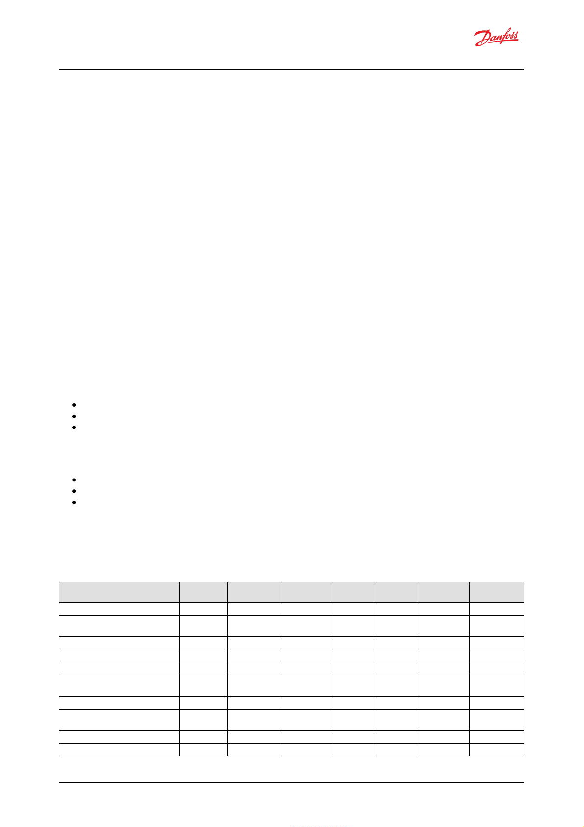
5.1.1 Single-service software
With single-service softw are the following comb inations are available:
Use case name CONTROL_MODE
_S1
CONTROL_REF_SR
_S1
FLOW_LIM_SRC
_S1
PWR_LIM_SRC
_S1
TRQ_LIM_SRC
_S1
PRESS_LIM_SRC
_S1
PUMPING_ENABLE
_SRC
Displacement control by PLUS+1® 0 1 0 0 0 0 1
Displacement control by PLUS+1® with torque
limit
0 1 0 0 1 1 1
Displacement control by J1939 0 2 0 0 0 1 2
Displacement control by J1939 with torque limit 0 2 0 0 2 1 2
Industrial pressure control by PLUS+1® 1 1 0 1 0 0 1
Industrial pressure control by PLUS+1® with
flow limit
1 1 1 1 0 0 1
Industrial pressure control by J1939 1 2 0 1 0 0 2
Industrial pressure control by J1939 with flow
limit
1 2 2 1 0 0 2
Load sensing pressure control by PLUS+1® 2 1 0 0 0 0 1
Load sensing pressure control by J1939 2 2 0 0 0 0 2
Software Manual
Digital Displacement® Pump Software Version 2.7.1
13 | © Danfoss | February 2022 BC404560709540en-000102
Page 14
Load sensing pressure control by PLUS+1® with
torque limit
2 1 0 0 2 0 2
Load sensing pressure control by J1939 with
torque limit
2 2 0 0 2 0 2
Use case name CONTROL_MODE
_S1
CONTROL_REF_SR
_S1
FLOW_LIM_SRC
_S1
PWR_LIM_SRC
_S1
TRQ_LIM_SRC
_S1
PRESS_LIM_SRC
_S1
PUMPING_ENABLE
_SRC
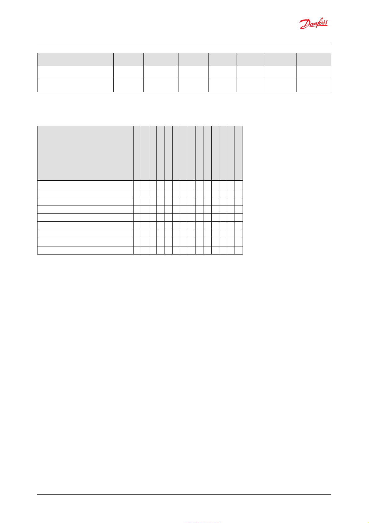
5.1.2 Two-service software
With tw o-service software the following combinations are available:
Use case name
Displacement control by PLUS+1® 0 0 1 1 0 0 0 0 0 0 0 0 1 1
Displacement control by J1939 with torque limit 0 0 2 2 0 0 0 0 2 2 1 1 2 2
Displacement control by PLUS+1® with torque limit 0 0 1 1 0 0 0 0 1 1 1 1 1 1
Industrial pressure control by J1939 with flow limit 1 1 2 2 2 2 0 0 0 0 0 0 1 2
Industrial pressure control by J1939 with flow limit #2 1 1 2 2 2 2 0 0 0 0 0 0 1 1
Industrial pressure control by PLUS+1® with flow limit 1 1 1 1 1 1 0 0 0 0 0 0 1 1
Load-sense pressure control by J1939 with torque limit 2 2 2 2 0 0 0 0 2 2 1 1 2 2
Load-sense pressure control by PLUS+1® with torque limit 2 2 1 1 0 0 0 0 1 1 1 1 1 1
Mixed displacement/LS by J1939 0 2 2 2 0 0 0 0 2 2 1 1 2 2
CO NTRO L_MODE_S1
CO NTRO L_MODE_S2
CO NTRO L_REF_SRC_ S1
CO NTRO L_REF_SRC_ S2
FLO W_LIM_ SRC_S1
FLO W_LIM_ SRC_S2
PW R_LIM_SRC _S1
PW R_LIM_SRC _S2
TR Q_LIM_SRC_S1
TR Q_LIM_SRC_S2
PRESS_L IM_SRC_S1
PRESS_L IM_SRC_S2
PUM PING_ENAB LE_SRC
SERV_ CONF_INDEX_SRC
Software Manual
Digital Displacement® Pump Software Version 2.7.1
14 | © Danfoss | February 2022 BC404560709540en-000102
Page 15
6 Two-service operation
Two-service DDP096 software (file named ML, marked GEN1_AB in Service Tool) is used w ith a DDP096 pump
fitte d with a multi-outlet endcap to allow the single pump and controlle r to provide flow to tw o hydraulic
circuits. The parame ters for both service 1 (marked _S1) and service 2 (marked _S2) must be configure d
suitably for the hyd raulic system or ve hicle.
6.1 Service independence
Each service controlled by the DDP096 software acts as an independe nt flow source.
Any coordination between the tw o services, for instance a whole-pump torque limit, must be calculated b y a
system controller and communicated to the pump as a control reference or limit per service.
6.2 Service switching
Service switching, also known as dynamic g anging, allows the allocation of some of the pumping units of the
pump to be switched from one control service to anothe r unde r the command of a system controller. The
DPC12 controlle r does not control the external valves or other hydraulic equipment needed to connect the
correct outlet ports of the DDP096 pump, this must be considered in the system controller design.
Warning
The physical hydraulic connections of the relevant output ports of the DDP096 pump must match the service
config uration selected. Mismatch could result in unintended flow to a particular service.
The twelve pumping units in the machine are group ed into four indepe nde nt groups, each consisting of three
interconnected pumping units. These groups are know n as "pump lets". An example of how the pumple ts,
pump ing units and outlet ports relate is shown below. Please refer to the Digital Displace ment® Pump Gen 1
DDP096 and DPC12 Technical Information for further information.
Pum plet Pum ping units O utlet port (three- outlet endcap)
1+3 A1, A3, B1, B3, C1, C3 P1
2 A2, B2, C2 P2
4 A4, B4, C4 P4
The service switching feature is controlled by supplying a config uration inde x (SERV_CONF_INDEX) to select
the active combination of pumplets assigned to the service . This index can be set statically in the PLUS+1®
Service Tool or commanded dynamically by a system controller over J1939. The following tab le describes the
pump let-to-service assignment for each available configuration:
Index Service 1 Service 2 No tes
0 1+3 2, 4
1 1+3 4 There is no flow from pumplet 2
2 1+3, 2 4
The service configuration can be change d w hile the pump is in operation. When command ing a service , the
flow, torque and power limit sig nals always re late to the real hydraulic output of the service. The
displace ment re ference is a fraction of the disp lacement available from the pumping units currently assigned
to a service; the available disp lacement may change as the service config uration is changed.
Warning
There will be a change in flow for a given displacement re ference command when the se rvice config uration is
changed under disp lacement control.
Software Manual
Digital Displacement® Pump Software Version 2.7.1
15 | © Danfoss | February 2022 BC404560709540en-000102
Page 16

7 Parameters
The DDP096 is a softw are-driven product and many parame ters are available to configure the softw are to the
user's requirements. These parameters are accessed using the Danfoss PLUS+1® Service Tool. This section
provides a list of all available parame ters w ith a de scription of their e ffect. Default, maximum and minimum
valid value s are also detailed in raw (unscale d) units.
The parameter interface uses integer types, and there fore the corre ct scaling must be applied to interpret
the data for fractional values.
7.1 Communication parameters
The DDP096 softw are on the DPC12 can be configured , controlled and monitore d over its CAN bus connection
using two protocols, the Danfoss PLUS+1® Service Tool interface and the SAE J1939 standard.
These parameters set up the config uration required to communicate with the DPC12 over the se interfaces.
Name
(r ead, write)
Descrip tion Service T ool Param eter
Name
Limit
Min
Limit
Max
Default
Valu e
Notes
Baud Rate
(R/W)
CAN Bus baud rate. BAUD_RATE 125 1000 250 Valid values: 125,
250, 500, 1000
Node address
(R/W)
Node address of controller.
Recommended address range is 208-223
NODE_ID 0 238 208 Boot node address
(PLUS+1®) = App
Node address
(J1939)
Function and ECU
Instance
(R/W)
Function and ECU instance for J1939 NAME. Bit [2:0] ECU instance value for
NAME (0 to 7). Bit [7:3] Function instance value for NAME (0 to 31).
FUN_ECU_INSTANCE 0 255 0
Ignore Error Passive
Flag
(R/W)
When enabled, the controller will ignore a "CAN error passive flag" error from
the CAN interface. If the controller is used in a system without a CAN bus, this
parameter should be enabled to allow pumping.
IGNORE_EPV_FLAG 0 1 0 0 - disabled, 1 -
enabled
Support DM13 PGN
(R/W)
When enabled, the controller ignores all Warning and Info level errors and the
pump is not allowed to produce flow until the "Start Diagnostic DM13" CAN
message is received. Useful for machine startup and engine cranking when
the power supply voltage may be low.
SUPPORT_DM13_PGN 0 1 1 0 - disabled, 1 -
enabled
Reset Error Counter
Command
(R/W)
Resets error counters to zero.
Each time the command is issued, up to 29 error counters are reset. Issue
command three times to ensure all error counters are reset.
RESET_ERR_CNTR_CMD 0 1 0 0- off, 1- start
7.2 Pump setting parameters
These parameters control hydraulic output features which are common to all of the services of the pump.
Name
(r ead, write)
Descrip tion Service T ool Param eter
Name
Limit
Min
Limit
Max
Default
Valu e
Notes
External Load-sense
Sensor Scale Service 1
(R/W)
The scale factor for the external load-sense sensor attached to the controller, if
used.
EXT_LS_SENS_SCALE_S1 625 6250 3750 in 0.01 bar/mA
External Load-sense
Sensor Scale Service 2
(R/W)
The scale factor for the external load-sense sensor attached to the controller, if
used.
EXT_LS_SENS_SCALE_S2 625 6250 3750 in 0.01 bar/mA
Pressure Error Limit
(R/W)
The pressure at which the "Pressure Too High Error" will be triggered. PRESS_ERROR_LIM 50 500 500 in bar
Shaft speed low Limit
(R/W)
Pump shaft speed below which the pump will not produce flow. Shaft speed
below limit error will be active below this speed.
SHAFT_SPD_LOW_LIM 300 3000 300 in rpm
Start Up Ramp Time
(R/W)
The start-up ramp limits the available displacement after reaching the
minimum allowed speed for pumping or enabling the pump for a set time. This
parameter sets the time over which this limit increases from 0% to 100%. The
output displacement set by the current control mode and references will be
restricted to this limit during this time. For further details see the Digital
Displacement® Pump Gen 1 DDP096 and DPC12 Technical Information.
START_UP_RAMP_TIME 0 100 0 in 0.1 seconds. Set to
0 to disable ramp.
Pumping Enable
Source
(R/W)
The source for the pumping enable signal. PUMPING_ENABLE_SRC 1 2 1 1- PLUS+1®, 2- J1939
Pumping Enable
(R/W)
Enables pumping of each service individually. PUMPING_ENABLE 0 255 0 Service 1 by bit 0,
Service 2 by bit 1.
Set other bits to 0.
Software Manual
Digital Displacement® Pump Software Version 2.7.1
16 | © Danfoss | February 2022 BC404560709540en-000102
Page 17

Service Configuration
Index Source
(R/W)
The source for the service configuration selection index. SERV_CONF_INDEX_SRC 1 2 1 1- PLUS+1®, 2- J1939
Service Configuration
Index
(R/W)
Selects the service configuration, assigning particular pumplets to a service,
from the pre-configured options.
SERV_CONF_INDEX 0 2 0 Refer to the Service
switching section for
more details.
Name
(r ead, write)
Descrip tion Service T ool Param eter
Name
Limit
Min
Limit
Max
Default
Valu e
Notes
7.3 Pump and controller status parameters
These parameters report status information which relates to the controlle r or entire pump.
Name
(r ead, write)
Descrip tion Service T ool Param eter
Name
Limit
Min
Limit
Max
Default
Valu e
Notes
Device Mode
(R)
Current mode of controller. DEVICE_MODE 0 2 0 0- Normal, 1- Limp,
2- Commissioning
Device State
(R)
Current state of controller when in Normal Mode. DEVICE_STATE 0 4 0 0 - Initialization, 1 -
Disabled, 2 - Active,
3 - Error, 4 - Error
Hold
Actual Shaft Speed
(R)
Current value of shaft speed read from pump shaft speed/temperature sensor.
Positive direction is clockwise when looking at the end of the input shaft.
ACTL_SHAFT_SPD -3500 3500 0 in rpm
Actual Pump
Temperature
(R)
Current value of pump temperature read from pump shaft speed/temperature
sensor.
ACTL_PUMP_TEMP -40 150 0 in °C
FPGA Revision Main
(R)
Build revision of the firmware running on the main controller's internal FPGA. FPGA_REVISION_MAIN 0 1060
7.4 Service 1 parameters
These parameters control hydraulic output features which are specific to Service 1 of the pump. Se e Control
config uration section for more details.
7.4.1 Control mode parameters
These parameters select the control mode of the pump and the source of the reference for the selected
control mode.
Name
(r ead, write)
Descrip tion Service T ool Param eter
Name
Limit
Min
Limit
Max
Default
Valu e
Notes
Control Mode Service
1
(R/W)
Sets the mode by which the service outlet flow is controlled. CONTROL_MODE_S1 0 2 0 0- Displacement
control, 1- Pressure
control, 2- Loadsense
Control Reference
Source Service 1
(R/W)
Interface to set the reference input to the selected control mode. CONTROL_REF_SRC_S1 1 2 1 1- PLUS+1®, 2- J1939
7.4.2 Control reference parameters
These parameters represent the refere nce values which are used in the current control mod e.
Only the paramete r for the currently selected control mode is used by the softw are.
The parameter operates differe ntly depe nd ing on the reference source selected. With the source set to
PLUS+1®, the value is set using this parameter. With the source se t to J1939, the value becomes read -only and
shows the last value received by the controller.
Name
(r ead, write)
Descrip tion Service T ool Param eter
Name
Limit
Min
Limit
Max
Default
Valu e
Notes
Displacement
Reference Service 1
(R/W)
The target displacement the pump should try to produce on this service as a
fraction of the available displacement.
DISP_REF_S1 0 10000 0 in 0.01 %
Pressure Reference
Service 1
(R/W)
The target pressure for the pump to maintain at its outlet when in pressure
control mode.
PRESS_REF_S1 0 420 0 in bar
Software Manual
Digital Displacement® Pump Software Version 2.7.1
17 | © Danfoss | February 2022 BC404560709540en-000102
Page 18
Pressure Margin
Reference Service 1
(R/W)
The target margin pressure for the pump to maintain between its outlet and
the external load-sense pressure sensor when in load-sense control mode.
PRESS_MARGIN_REF_S1 0 100 0 in bar
Name
(r ead, write)
Descrip tion Service T ool Param eter
Name
Limit
Min
Limit
Max
Default
Valu e
Notes
7.4.3 Limits parameters
The limits available are ap plied to the d isplacement de mand from the selecte d control mode. Each limit is
applied such that the output of the service will be restricted to the lowest limit supplied. Each limit can be
supplied by either J1939 or PLUS+1®.
Each limit parameter operates differently depending on the re ference source selected. With the source set to
PLUS+1®, the value is set using the limit parameter. With the source set to J1939, the value becomes read only and the limit parameter shows the last value re ceive d by the controller.
Name
(r ead, write)
Descrip tion Service T ool Param eter
Name
Limit
Min
Limit
Max
Default
Valu e
Notes
Pressure Limit Source
Service 1
(R/W)
The limit value source for the service pressure limiting feature. PRESS_LIM_SRC_S1 0 1 0 0- Unlimited, 1-
PLUS+1®
Pressure Low Limit
Service 1
(R/W)
The pressure at which the displacement limit for pressure equals 100%. The
displacement limit for pressure decreases linearly between Pressure Low Limit
and Pressure High Limit as pressure increases.
PRESS_LOW_LIM_S1 0 420 0 in bar
Pressure High Limit
Service 1
(R/W)
The pressure at which the displacement limit for pressure equals 0%. The
displacement limit for pressure decreases linearly between Pressure Low Limit
and Pressure High Limit as pressure increases.
PRESS_HIGH_LIM_S1 0 450 0 in bar
Flow Limit Source
Service 1
(R/W)
The limit value source for the service flow limiting feature. FLOW_LIM_SRC_S1 0 2 0 0- Unlimited, 1-
PLUS+1®, 2- J1939
Flow Limit Service 1
(R/W)
The maximum allowed flow in terms of theoretical displacement of the pump,
which does not account for oil compressibility and pump shrinkage. The pump
will adjust the service displacement according to the shaft speed in order to
stay below this limit.
FLOW_LIM_S1 0 300 0 in L/min
Torque Limit Source
Service 1
(R/W)
The limit value source for the service torque limiting feature. TRQ_LIM_SRC_S1 0 2 0 0- Unlimited, 1-
PLUS+1®, 2- J1939
Torque Limit Service 1
(R/W)
The maximum torque allowed to be applied by the service. The pump will
adjust the service displacement according to the outlet pressure in order to stay
below this limit.
TRQ_LIM_S1 0 1500 0 in Nm
Power Limit Source
Service 1
(R/W)
The limit value source for the service power limiting feature. PWR_LIM_SRC_S1 0 2 0 0- Unlimited, 1-
PLUS+1®, 2- J1939
Power Limit Service 1
(R/W)
The maximum power allowed to be consumed by the service. The pump will
adjust the service displacement according to the outlet pressure and shaft
speed in order to stay below this limit.
PWR_LIM_S1 0 500 0 in kW
7.4.4 Control loop gain parameters
These parameters allow the user to tune the pressure control loop proportional-integrator (PI) gains to give
the pump the best pressure response in their particular system. The gains are used in both pressure control
and load -sense control modes.
The read-only parameters in the service status section allow various parts of the PI loop to be inspecte d while
the pump is running.
Name
(r ead, write)
Descrip tion Service T ool Param eter
Name
Limit
Min
Limit
Max
Default
Valu e
Notes
Pressure Reference
Limit Service 1
(R/W)
Limits maximum value of Actual Reference Pressure, the pressure the pump
tries to maintain on its outlet in pressure control or load-sense control modes.
PRESS_REF_LIM_S1 0 420 0 in bar
Pressure Small Gain
Service 1
(R/W)
The small proportional gain in the pressure control loop. PRESS_SMALL_GAIN_S1 0 10000 0 in 0.001 %/bar
Pressure Small Gain
Threshold Service 1
(R/W)
The minimum pressure error needed for the small gain to take effect. PRESS_SMALL_GAIN_THR
ESH_S1
0 600 0 in bar
Software Manual
Digital Displacement® Pump Software Version 2.7.1
18 | © Danfoss | February 2022 BC404560709540en-000102
Page 19

Pressure Gain Big Gain
Service 1
(R/W)
The big proportional gain in the pressure control loop. PRESS_BIG_GAIN_S1 0 50000 0 in 0.001 %/bar
Pressure Big Gain
Threshold Service 1
(R/W)
The minimum pressure error needed for the big gain to take effect. PRESS_BIG_GAIN_THRES
H_S1
0 600 600 in bar
Pressure Integration
Time Service 1
(R/W)
The integration time for the integrator in the pressure control loop. PRESS_INTEG_TIME_S1 0 10000 0 in ms
Pressure Integration
Max Disp Service 1
(R/W)
The maximum displacement of the integrator in the pressure control loop. PRESS_INTEG_MAX_DISP
_S1
0 10000 10000 in 0.01 %
Pressure Integration
Min Disp Service 1
(R/W)
The minimum displacement of the integrator in the pressure control loop. PRESS_INTEG_MIN_DISP
_S1
-10000 0 0 in 0.01 %
Name
(r ead, write)
Descrip tion Service T ool Param eter
Name
Limit
Min
Limit
Max
Default
Valu e
Notes
7.4.5 Service status parameters
These parameters report the current values produced by the software's control loop and the hyd raulic outp ut
of the service .
Name
(r ead, write)
Descrip tion Service T ool Param eter
Name
Limit
Min
Limit
Max
Default
Valu e
Notes
Actual Displacement
Service 1
(R)
Current value of displacement after all limits have been applied. ACTL_DISP_S1 0 10000 0 in 0.01%
Actual Pressure
Reference Service 1
(R)
Current value of pressure used for the pressure control loop after pressure
margin reference (load-sense control only) and pressure reference limit are
applied.
ACTL_PRESS_REF_S1 0 600 0 in bar
Actual Pressure
Service 1
(R)
The current pressure read from the outlet pressure sensor. ACTL_PRESS_S1 0 600 0 in bar
Actual Pressure
Margin Reference
Service 1
(R)
Current value of margin pressure setpoint for used in the control loop. ACTL_PRESS_MARGIN_RE
F_S1
0 100 0 in bar
Actual Load Sensing
Pressure Service 1
(R)
The current pressure read from the external load sense pressure sensor in loadsense control mode.
ACTL_LS_PRESS_S1 0 1000 0 in bar
Actual Small Gain
Displacement Service
1
(R)
Current value of displacement commanded by the small gain portion of the
pressure control loop.
ACTL_SMALL_GAIN_DISP
_S1
-1091090 in 0.01%
Actual Big Gain
Displacement Service
1
(R)
Current value of displacement commanded by the big gain portion of the
pressure control loop.
ACTL_BIG_GAIN_DISP_S1-1091090 in 0.01%
Actual Integrator
Displacement Service
1
(R)
Current value of displacement commanded by the integrator portion of the
pressure control loop.
ACTL_INTEG_DISP_S1 -10000 10000 0 in 0.01%
Actual Pressure
Control Loop
Displacement Service
1
(R)
Current value of displacement commanded by the pressure control loop before
limiting.
ACTL_PRESS_CTRL_LOOP
_DISP_S1
0 10000 0 in 0.01%
7.5 Service 2 parameters
The Service 2 parameters are used to control Service 2 in two-service software. The function of each is the
same as the correspond ing Se rvice 1 parameter — refe r to the Service 1 parameters section further
descriptions. When using singe-service softw are the Service 2 parameters have no effect and may be
remove d from single-service software in a future release.
Software Manual
Digital Displacement® Pump Software Version 2.7.1
19 | © Danfoss | February 2022 BC404560709540en-000102
Page 20

7.5.1 Control mode parameters
Name
(r ead, write)
Descrip tion Service T ool Param eter
Name
Limit
Min
Limit
Max
Default
Valu e
Notes
Control Mode Service
2
(R/W)
Sets the mode by which the service outlet flow is controlled. CONTROL_MODE_S2 0 2 0 0- Displacement
control, 1- Pressure
control, 2- Loadsense
Control Reference
Source Service 2
(R/W)
Interface to set the reference input to the selected control mode. CONTROL_REF_SRC_S2 1 2 1 1- PLUS+1®, 2- J1939
7.5.2 Control reference parameters
Name
(r ead, write)
Descrip tion Service T ool Param eter
Name
Limit
Min
Limit
Max
Default
Valu e
Notes
Displacement
Reference Service 2
(R/W)
The target displacement the pump should try to produce on this service as a
fraction of the available displacement.
DISP_REF_S2 0 10000 0 in 0.01 %
Pressure Reference
Service 2
(R/W)
The target pressure for the pump to maintain at its outlet when in pressure
control mode.
PRESS_REF_S2 0 420 0 in bar
Pressure Margin
Reference Service 2
(R/W)
The target margin pressure for the pump to maintain between its outlet and
the external load-sense pressure sensor when in load-sense control mode.
PRESS_MARGIN_REF_S2 0 100 0 in bar
7.5.3 Limits parameters
Name
(r ead, write)
Descrip tion Service T ool Param eter
Name
Limit
Min
Limit
Max
Default
Valu e
Notes
Pressure Limit Source
Service 2
(R/W)
The limit value source for the service pressure limiting feature. PRESS_LIM_SRC_S2 0 1 0 0- Unlimited, 1-
PLUS+1®
Pressure Low Limit
Service 2
(R/W)
The pressure at which the displacement limit for pressure equals 100%. The
displacement limit for pressure decreases linearly between Pressure Low Limit
and Pressure High Limit as pressure increases.
PRESS_LOW_LIM_S2 0 420 0 in bar
Pressure High Limit
Service 2
(R/W)
The pressure at which the displacement limit for pressure equals 0%. The
displacement limit for pressure decreases linearly between Pressure Low Limit
and Pressure High Limit as pressure increases.
PRESS_HIGH_LIM_S2 0 450 0 in bar
Flow Limit Source
Service 2
(R/W)
The limit value source for the service flow limiting feature. FLOW_LIM_SRC_S2 0 2 0 0- Unlimited, 1-
PLUS+1®, 2- J1939
Flow Limit Service 2
(R/W)
The maximum allowed flow in terms of theoretical displacement of the pump,
which does not account for oil compressibility and pump shrinkage. The pump
will adjust the service displacement according to the shaft speed in order to
stay below this limit.
FLOW_LIM_S2 0 300 0 in L/min
Torque Limit Source
Service 2
(R/W)
The limit value source for the service torque limiting feature. TRQ_LIM_SRC_S2 0 2 0 0- Unlimited, 1-
PLUS+1®, 2- J1939
Torque Limit Service 2
(R/W)
The maximum torque allowed to be applied by the service. The pump will
adjust the service displacement according to the outlet pressure in order to stay
below this limit.
TRQ_LIM_S2 0 1500 0 in Nm
Power Limit Source
Service 2
(R/W)
The limit value source for the service power limiting feature. PWR_LIM_SRC_S2 0 2 0 0- Unlimited, 1-
PLUS+1®, 2- J1939
Power Limit Service 2
(R/W)
The maximum power allowed to be consumed by the service. The pump will
adjust the service displacement according to the outlet pressure and shaft
speed in order to stay below this limit.
PWR_LIM_S2 0 500 0 in kW
7.5.4 Control loop gain parameters
Name
(r ead, write)
Descrip tion Service T ool Param eter
Name
Limit
Min
Limit
Max
Default
Valu e
Notes
Pressure Reference
Limit Service 2
(R/W)
Limits maximum value of Actual Reference Pressure, the pressure the pump
tries to maintain on its outlet in pressure control or load-sense control modes.
PRESS_REF_LIM_S2 0 420 0 in bar
Pressure Small Gain
Service 2
(R/W)
The small proportional gain in the pressure control loop. PRESS_SMALL_GAIN_S2 0 10000 0 in 0.001 %/bar
Software Manual
Digital Displacement® Pump Software Version 2.7.1
20 | © Danfoss | February 2022 BC404560709540en-000102
Page 21

Pressure Small Gain
Threshold Service 2
(R/W)
The minimum pressure error needed for the small gain to take effect. PRESS_SMALL_GAIN_THR
ESH_S2
0 600 0 in bar
Pressure Gain Big Gain
Service 2
(R/W)
The big proportional gain in the pressure control loop. PRESS_BIG_GAIN_S2 0 50000 0 in 0.001 %/bar
Pressure Big Gain
Threshold Service 2
(R/W)
The minimum pressure error needed for the big gain to take effect. PRESS_BIG_GAIN_THRES
H_S2
0 600 600 in bar
Pressure Integration
Time Service 2
(R/W)
The integration time for the integrator in the pressure control loop. PRESS_INTEG_TIME_S2 0 10000 0 in ms
Pressure Integration
Max Disp Service 2
(R/W)
The maximum displacement of the integrator in the pressure control loop. PRESS_INTEG_MAX_DISP
_S2
0 10000 10000 in 0.01 %
Pressure Integration
Min Disp Service 2
(R/W)
The minimum displacement of the integrator in the pressure control loop. PRESS_INTEG_MIN_DISP
_S2
-10000 0 0 in 0.01 %
Name
(r ead, write)
Descrip tion Service T ool Param eter
Name
Limit
Min
Limit
Max
Default
Valu e
Notes
7.5.5 Service status parameters
Name
(r ead, write)
Descrip tion Service T ool Param eter
Name
Limit
Min
Limit
Max
Default
Valu e
Notes
Actual Displacement
Service 2
(R)
Current value of displacement after all limits have been applied. ACTL_DISP_S2 0 10000 0 in 0.01%
Actual Pressure
Reference Service 2
(R)
Current value of pressure used for the pressure control loop after pressure
margin reference (load-sense control only) and pressure reference limit are
applied.
ACTL_PRESS_REF_S2 0 600 0 in bar
Actual Pressure
Service 2
(R)
The current pressure read from the outlet pressure sensor. ACTL_PRESS_S2 0 600 0 in bar
Actual Pressure
Margin Reference
Service 2
(R)
Current value of margin pressure setpoint for used in the control loop. ACTL_PRESS_MARGIN_RE
F_S2
0 100 0 in bar
Actual Load Sensing
Pressure Service 2
(R)
The current pressure read from the external load sense pressure sensor in loadsense control mode.
ACTL_LS_PRESS_S2 0 1000 0 in bar
Actual Small Gain
Displacement Service
2
(R)
Current value of displacement commanded by the small gain portion of the
pressure control loop.
ACTL_SMALL_GAIN_DISP
_S2
-1091090 in 0.01%
Actual Big Gain
Displacement Service
2
(R)
Current value of displacement commanded by the big gain portion of the
pressure control loop.
ACTL_BIG_GAIN_DISP_S2-1091090 in 0.01%
Actual Integrator
Displacement Service
2
(R)
Current value of displacement commanded by the integrator portion of the
pressure control loop.
ACTL_INTEG_DISP_S2 -10000 10000 0 in 0.01%
Actual Pressure
Control Loop
Displacement Service
2
(R)
Current value of displacement commanded by the pressure control loop before
limiting.
ACTL_PRESS_CTRL_LOOP
_DISP_S2
0 10000 0 in 0.01%
7.6 Other parameters
Name
(r ead, write)
Descrip tion Service T ool Param eter
Name
Limit
Min
Limit
Max
Default
Valu e
Notes
Suppress Power
Supply below limit
error when Shaft
speed below low limit
(R/W)
When enabled, the Power Supply Below Limit error will not be triggered when
the shaft speed is below its low limit. Useful during engine cranking when the
power supply voltage may be low and Support DM13 PGN is disabled.
SUPPRESS_PWR_SUPPLY_
ERR_BLW_LOW_SPD
0 1 0 0 - disabled, 1 -
enabled
Shaft Max Smoothing
Count
(R/W)
Used to interpret the speed sensor signal. Danfoss recommends using the
default value. If tuning is required, contact Danfoss.
SHAFT_SPD_SMTH_COUNT 0 100 13 Number of shaft
sensor edges
Software Manual
Digital Displacement® Pump Software Version 2.7.1
21 | © Danfoss | February 2022 BC404560709540en-000102
Page 22

Shaft Max Smoothing
Period
(R/W)
Used to interpret the speed sensor signal. Danfoss recommends using the
default value. If tuning is required, contact Danfoss.
SHAFT_SPD_SMTH_PERIOD0 32767 32767 x 0.02 ms
Shaft Max Smoothing
Angle
(R/W)
Used to interpret the speed sensor signal. Danfoss recommends using the
default value. If tuning is required, contact Danfoss.
SHAFT_SPD_SMTH_ANGLE 0 7200 7200 x 0.1 degrees
Enable Manual
Solenoid Test
(R/W)
Causes the DPC12 to perform a user-initiated test on the electrical
characteristics of the low pressure valve solenoids to determine if they are
present and to detect wiring faults.
EN_MANUAL_SOLENOID_F
AULT_TEST
0 1 0 0 - disabled, 1 -
manual trigger
Enable Startup
Solenoid Test
(R/W)
Sets the controller to automatically perform a test at startup on the electrical
characteristics of the low pressure valve solenoids to determine if they are
present and to detect wiring faults. In order to protect the output electronics,
this diagnostic test runs before any solenoids are used normally.
EN_STARTUP_SOLENOID_
FAULT_TEST
0 1 1 0 - disabled, 1 -
enabled at startup
Solenoid Test
Execution Counter
(R)
Number of solenoid fault tests carried out. SOLENOID_FAULT_TEST_
CNTR
0 255 0 Number of tests
Valve Adaptation
Algorithm Maximum
Broken Valves Limit
Service 1
(R/W)
Maximum number of broken valves assigned to Service 1 to maintain
operation with valve adaptation algorithm. If more valves are broken, the
"Valve adaptation algorithm failed - too many valves broken" error is triggered.
VALVE_ADPT_ALG_MAX_B
RKN_VALVS_LIM_S1
0 11 0 Number of broken
valves
Valve Adaptation
Algorithm Maximum
Broken Valves Limit
Service 2
(R/W)
Maximum number of broken valves assigned to Service 2 to maintain
operation with valve adaptation algorithm. If more valves are broken, the
"Valve adaptation algorithm failed - too many valves broken" error is triggered.
VALVE_ADPT_ALG_MAX_B
RKN_VALVS_LIM_S2
0 11 0 Number of broken
valves
Limp Mode Number
of Required Valves
Service 1
(R/W)
The number of cylinders which should be enabled for the service when Limp
Home Mode is active.
LIMP_MODE_NUM_REQ_VA
LVES_S1
1 3 1 Limp Home Mode is
not included in this
release
Limp Mode Number
of Required Valves
Service 2
(R/W)
The number of cylinders which should be enabled for the service when Limp
Home Mode is active.
LIMP_MODE_NUM_REQ_VA
LVES_S2
1 3 1 Limp Home Mode is
not included in this
release
Name
(r ead, write)
Descrip tion Service T ool Param eter
Name
Limit
Min
Limit
Max
Default
Valu e
Notes
7.7 Commissioning mode parameters
The parameters are used during Commissioning mode.
Name
(r ead, write)
Descrip tion Service T ool Param eter
Name
Limit
Min
Limit
Max
Default
Valu e
Notes
Enable
Commissioning
(R/W)
To enter Commissioning Mode, set to "enabled", then power cycle the
controller. To exit, set to "disabled", then power cycle the controller.
EN_COMMISS 0 1 0 0 - disabled, 1 -
enabled
Commissioning Action
Type
(R/W)
Chooses between different Commissioning Mode actions. Fire: actuates the
specified coil as soon as possible. Pump: actuates the specified coil at the correct
shaft position to enable the cylinder to pump a full stroke. Raw Displacement:
actuates coils as necessary to achieve the desired percentage of displacement.
COMMISS_ACT_TYPE 0 5 0 0- off, 1- fire, 2-
pump 1x, 3- pump
100x, 4- raw
displacement
Service 1, 5- raw
displacement
Service 2
Commissioning Value
(R/W)
Specifies the coil or raw displacement for the corresponding Commissioning
Action Type.
COMMISS_VALUE 0 10000 0 coil number OR raw
displacement value
Commissioning
Command
(R/W)
For Fire and Pump actions, transition from 0 to 1 starts the action. Must be reset
to 0 before starting action again. For Raw Displacement action, pump will
produce desired displacement while set to 1 and stop pumping when set to 0.
COMMISS_CMD 0 1 0 0- off, 1- start
Commissioning Level
(R)
Indicates what level of commissioning operation can be done on the pump
due to severity of active errors.
COMMISS_LEVEL 0 2 0 0 - disabled, 1 -
firing, 2 - pumping
Commissioning Status
(R)
Indicates if an action is off, running, or denied. COMMISS_STATUS 0 2 0 0- off, 1- running, 2-
denied
Software Manual
Digital Displacement® Pump Software Version 2.7.1
22 | © Danfoss | February 2022 BC404560709540en-000102
Page 23

8 Errors
The DDP096 softw are contains an error-handling system w hich is d esigned to protect the pump and system
from undesirable be havior when there is an error de tected w ith the software, communications, DPC12
hardware, sensors or DDP096 pump.
The e rror handling system consists of a number of errors (see Error list section) each of which has a severity
which governs the error handler's response when the error is detecte d. The effect of each severity is:
Info: no effect on operation.
Warning: normal operation stopped. error ig nored in disable d state (when SUPPORT_DM13_PGN
parame ter is enabled).
Critical: normal operation stoppe d.
Severe: normal operation stoppe d. Fault state cannot be reset by DM 11 message.
Two me chanisms e xist to return the controlle r to an active state following a fault - the J1939 DM11 message
(see DM 11 PGN - diagnostics data clear of active DTCs section) or power-cycling the DPC12 controller.
Active and previously active errors can be read over CAN bus using standard J1939 me chanisms (see DM1
PGN - active diagnostic trouble codes and DM 2 PGN - previously active diagnostics trouble codes sections) or
by using the PLUS+1® Se rvice Tool to read the associated parameters. The PLUS+1® Service Tool can also
display counters for the numbe r of times each error has occurred since the last error counter reset (via the
DM3 messag e, se e DM3 PGN - diagnostics d ata clear of p reviously active DTCs section, or
RESET_ERR_CNTR_CMD paramete r).
8.1 Error handler states
The e rror handler component op erates as a state machine for the w hole DDP096 software. The states are
explained in the table below.
State DEVICE_STATE code Descriptio n
Initialization 0 Start-up state
Disabled 1 Software is held in this state until reception of DM13 message if SUPPORT_DM13_PGN parameter is enabled.
Active 2 Normal operation
Fault 3 There is an active fault of severity warning, critical or severe, or there was previously a severe fault. Pump does not operate.
Fault hold 4 All previous faults non-severe faults have been cleared, but software remains inactive until reception of DM11 message.
The transitions be tween states are show n in the flowchart below .
Software Manual
Digital Displacement® Pump Software Version 2.7.1
23 | © Danfoss | February 2022 BC404560709540en-000102
Page 24

Initialization
Disabled Fault hold
Active Fault
1 =
enabled
0 = disabled
SUPPORT_
DM13_PGN
Yes
No
DM13
received since
startup? Yes
No
Was there a
severe error?
Yes
No
Are all
non-info errors
cleared?
No
Yes
Critical
or severe errors
active
Yes
No
Non-info
error active
Yes
No
DM11
received
No
Yes
Non-info
error active
8.2 Error list
SPN FMI Name Des criptio n Severity Ser vice Tool nam e for active
err or
Service T ool name for erro r
coun ter
168 3 Power supply above limit Power supply voltage greater than 36V. WARNING ERR_AE_168_03_LM_SPLYVIN ERR_OC_168_03_LM_SPLYVIN
168 4 Power supply below limit Power supply voltage less than 9V. WARNING ERR_AE_168_04_LM_SPLYVIN ERR_OC_168_04_LM_SPLYVIN
441 16 Controller temperature above
limit
Internal controller temperature above limit. CRITICAL ERR_AE_441_16_LM_CTEMP ERR_OC_441_16_LM_CTEMP
441 17 Controller temperature below
limit
Controller temperature below -40°C. Pumping will
not be affected.
INFO ERR_AE_441_17_LM_CTEMP ERR_OC_441_17_LM_CTEMP
442 16 Pump temperature above
limit
Pump temperature above 90°C. CRITICAL ERR_AE_442_16_LM_PTEMP ERR_OC_442_16_LM_PTEMP
442 17 Pump temperature below limit Pump temperature below -20°C. Pumping will not
be affected. Error will clear once temperature rises
above limit.
INFO ERR_AE_442_17_LM_PTEMP ERR_OC_442_17_LM_PTEMP
2848 31 J1939 Name conflict The configured J1939 Name of the DPC12
controller conflicted with another device on the
CAN bus during the address claim procedure.
The controller will not comminucate over J1939.
Ensure all DPC12 controllers on the bus have their
FUN_ECU_INSTANCE parameters set to a
unique value.
SEVERE ERR_AE_2848_31_CA_NAME_CLM ERR_OC_2848_31_CA_NAME_CLM
3599 2 Internal 24V out of range Internal 24V power supply is out of range. Check
that coil power supply pins are powered with the
correct voltage. If error persists, contact Danfoss for
help.
SEVERE ERR_AE_3599_02_LM_OUT24V ERR_OC_3599_02_LM_OUT24V
8621 2 EEPROM CRC fault Parameter data in non-volatile memory is
corrupted and pump cannot operate. Connect
with PLUS+1® Service Tool and reset values in
controller.
SEVERE ERR_AE_8621_02_COM_ROMCRC ERR_OC_8621_02_COM_ROMCRC
8621 11 EEPROM SPI fault A communication error has occurred when
accessing non-volatile memory. No action is
required.
INFO ERR_AE_8621_11_COM_ROMSPI ERR_OC_8621_11_COM_ROMSPI
8621 31 EEPROM occurrence counter
CRC fault
Error occurrence counter data in non-volatile
memory is corrupted. Counters will be reset to
zero.
WARNING ERR_AE_8621_31_COM_ROMCRC_OCERR_OC_8621_31_COM_ROMCRC_
OC
Software Manual
Digital Displacement® Pump Software Version 2.7.1
24 | © Danfoss | February 2022 BC404560709540en-000102
Page 25

520960 0 Service 1 outlet pressure too
high
Outlet pump pressure above pressure limit, as set
by PRESS_ERROR_LIM parameter.
SEVERE ERR_AE_520960_00_SENSOR_OUTP
RESS_S1
ERR_OC_520960_00_SENSOR_OUT
PRESS_S1
520960 2 Service 1 outlet pressure
sensor incorrect
Analogue outlet pressure sensor signal is erratic or
unstable. Check that sensor and connectors are
properly secured and for damage to sensor wires
or sensor. Repair as necessary. If no damage exists
and error persists, or to obtain replacement parts,
contact Danfoss for help.
SEVERE ERR_AE_520960_02_SENSOR_OUTP
RESS_S1
ERR_OC_520960_02_SENSOR_OUT
PRESS_S1
520960 16 Service 1 outlet pressure
reading above maximu m
Analogue outlet pressure sensor signal is above
the valid 4-20 mA range. Check that sensor and
connectors are properly secu red and for damage
to sensor wires or sensor. Repair as necessary. If no
damage exists and error persists, or to obtain
replacement parts, contact Danfoss for help.
SEVERE ERR_AE_520960_16_SENSOR_OUTP
RESS_S1
ERR_OC_520960_16_SENSOR_OUT
PRESS_S1
520960 18 Service 1 outlet pressure
reading below minimum
Analogue outlet pressure sensor signal is below
the valid 4-20 mA range. Check that sensor and
connectors are properly secu red and for damage
to sensor wires or sensor. Repair as necessary. If no
damage exists and error persists, or to obtain
replacement parts, contact Danfoss for help.
SEVERE ERR_AE_520960_18_SENSOR_OUTP
RESS_S1
ERR_OC_520960_18_SENSOR_OUT
PRESS_S1
520961 0 Service 2 outlet pressure too
high
Outlet pump pressure above pressure limit, as set
by PRESS_ERROR_LIM parameter.
SEVERE ERR_AE_520961_00_SENSOR_OUTP
RESS_S2
ERR_OC_520961_00_SENSOR_OUT
PRESS_S2
520961 2 Service 2 outlet pressure
sensor incorrect
Analogue outlet pressure sensor signal is erratic or
unstable. Check that sensor and connectors are
properly secured and for damage to sensor wires
or sensor. Repair as necessary. If no damage exists
and error persists, or to obtain replacement parts,
contact Danfoss for help.
SEVERE ERR_AE_520961_02_SENSOR_OUTP
RESS_S2
ERR_OC_520961_02_SENSOR_OUT
PRESS_S2
520961 16 Service 2 outlet pressure
reading above maximu m
Analogue outlet pressure sensor signal is above
the valid 4-20 mA range. Check that sensor and
connectors are properly secu red and for damage
to sensor wires or sensor. Repair as necessary. If no
damage exists and error persists, or to obtain
replacement parts, contact Danfoss for help.
SEVERE ERR_AE_520961_16_SENSOR_OUTP
RESS_S2
ERR_OC_520961_16_SENSOR_OUT
PRESS_S2
520961 18 Service 2 outlet pressure
reading below minimum
Analogue outlet pressure sensor signal is below
the valid 4-20 mA range. Check that sensor and
connectors are properly secu red and for damage
to sensor wires or sensor. Repair as necessary. If no
damage exists and error persists, or to obtain
replacement parts, contact Danfoss for help.
SEVERE ERR_AE_520961_18_SENSOR_OUTP
RESS_S2
ERR_OC_520961_18_SENSOR_OUT
PRESS_S2
520972 2 J1939 address invalid The stored configuration for J1939 Name
(FUN_ECU_INSTANCE and NODE_ID are
invalid. Check the parameters are in the valid
range.
SEVERE ERR_AE_520972_02_CA_ADDRS_CFGERR_OC_520972_02_CA_ADDRS_C
FG
520972 31 J1939 address claim failure The DPC12 controller has lost arbitration for the
configured J1939 address. The controller will not
communicate over J1939. Review device address
configuration in the CAN bus system.
SEVERE ERR_AE_520972_31_CA_ADDRS_CLMERR_OC_520972_31_CA_ADDRS_C
LM
520975 0 Shaft speed above limit Shaft speed is too high to pump. CRITICAL ERR_AE_520975_00_LM_SHSPD ERR_OC_520975_00_LM_SHSPD
520975 2 Shaft sensor detection fault Shaft speed sensor not working properly. Power
cycle controller to enable pumping. If error
persists, check that connectors are properly
secu red and for damage to sensor wires or sensor.
Repair as necessary. If no damage exists and error
persists, or to obtain replacement parts, contact
Danfoss for help.
SEVERE ERR_AE_520975_02_LM_SHSPD ERR_OC_520975_02_LM_SHSPD
520975 8 Reverse shaft direction Shaft is rotating in reverse direction (counter-
clockwise when looking at input shaft) which is
not supported. Correct the direction of rotation.
WARNING ERR_AE_520975_08_LM_SHSPD ERR_OC_520975_08_LM_SHSPD
520975 17 Shaft speed below limit Shaft speed is too low to pump. Pumping
disabled. Increase shaft speed to enable
pumping.
INFO ERR_AE_520975_17_LM_SHSPD ERR_OC_520975_17_LM_SHSPD
520976 2 EEPROM value out of range A parameter value stored in non-volatile memory
is outside its allowed range. Connect with
PLUS+1® Service Tool and check values.
CRITICAL ERR_AE_520976_02_LM_NVDATA ERR_OC_520976_02_LM_NVDATA
520977 16 Too many errors to handle by
J1939 DM1
More than 29 errors active (or previously active) at
the same time. J1939 Diagnostic messages DM1
and DM2 are not able to show them all.
CRITICAL ERR_AE_520977_16_LM_FAULTMAXERR_OC_520977_16_LM_FAULTMA
X
520978 9 CAN bus displacement
reference timeout
J1939 displacement reference message is
required by current control mode configuration
and was not received within the timeout window.
Check configuration, message content and
sending frequency.
WARNING ERR_AE_520978_09_TL_DSREF ERR_OC_520978_09_TL_DSREF
SPN FMI Name Des criptio n Severity Ser vice Tool nam e for active
err or
Service T ool name for erro r
coun ter
Software Manual
Digital Displacement® Pump Software Version 2.7.1
25 | © Danfoss | February 2022 BC404560709540en-000102
Page 26

520979 9 CAN bus torque limit timeout J1939 torque limit message is required by current
limit configuration and was not received within
the timeout window. Check configuration,
message content and sendin g frequency.
WARNING ERR_AE_520979_09_TL_TQLIM ERR_OC_520979_09_TL_TQLIM
520980 9 CAN bus pressure reference
timeout
J1939 pressure reference message is required by
current control mode configuration and was not
received within the timeout window. Check
configuration, message content and sending
frequency.
WARNING ERR_AE_520980_09_TL_PRREF ERR_OC_520980_09_TL_PRREF
520981 9 CAN bus pressure margin
timeout
J1939 pressure margin reference message is
required by current control mode configuration
and was not received within the timeout window.
Check configuration, message content and
sending frequency.
WARNING ERR_AE_520981_09_TL_PMREF ERR_OC_520981_09_TL_PMREF
520982 9 CAN bus power limit timeout J1939 power limit message is required by current
limit configuration and was not received within
the timeout window. Check configuration,
message content and sendin g frequency.
WARNING ERR_AE_520982_09_TL_PWRLIM ERR_OC_520982_09_TL_PWRLIM
520983 9 CAN bus pump
enable/service index timeout
J1939 pump setup message is required by
current configuration and was not received within
the timeout window. Check configuration,
message content and sendin g frequency.
WARNING ERR_AE_520983_09_TL_PMPEN ERR_OC_520983_09_TL_PMPEN
520984 9 CAN bus flow limit timeout J1939 flow limit message is required by current
limit configuration and was not received within
the timeout window. Check configuration,
message content and sendin g frequency.
WARNING ERR_AE_520984_09_TL_FLLIM ERR_OC_520984_09_TL_FLLIM
520987 16 Service 1 broken valves above
maximum
Too many valves are not functioning properly.
Check other error codes to see which valves are
not functioning. For further help, contact Danfoss.
CRITICAL ERR_AE_520987_16_LM_BROKENVL
VMAX_S1
ERR_OC_520987_16_LM_BROKENV
LVMAX_S1
520988 16 Service 2 broken valves above
maximum
Too many valves are not functioning properly.
Check other error codes to see which valves are
not functioning. For further help, contact Danfoss.
CRITICAL ERR_AE_520988_16_LM_BROKENVL
VMAX_S2
ERR_OC_520988_16_LM_BROKENV
LVMAX_S2
520995 1 Service 1 unbroken valves
below limping minumum S1
Not implemented in this version SEVERE ERR_AE_520995_01_LM_LIMPVLVM
IN_S1
ERR_OC_520995_01_LM_LIMPVLV
MIN_S1
520996 1 Service 2 unbroken valves
below limping minimum
Not implemented in this version SEVERE ERR_AE_520996_01_LM_LIMPVLVM
IN_S2
ERR_OC_520996_01_LM_LIMPVLV
MIN_S2
521003 2 Internal 3.3V out of range Internal 3.3V power supply is out of range. If error
persists, contact Danfoss for help.
SEVERE ERR_AE_521003_02_LM_OUT3V3 ERR_OC_521003_02_LM_OUT3V3
521005 2 Invalid data in J1939 message Data in at least one J1939 CAN message is outside
range limits. CAN message is ignored. Ensure that
J1939 CAN messages are implemented correctly
for all required CAN messages. For CAN message
definitions, refer J1939 CAN protocol section.
WARNING ERR_AE_521005_02_INVALID_DATAERR_OC_521005_02_INVALID_DAT
A
521006 2 Unsupported DD
configuration
Configuration provided by user via PLUS+1®
Service Tool is not supported by controller. After
valid configuration is provided (refer to Use cases
section for available settings), power cycle the
controller to clear error. If error persists, contact
Danfoss for help.
CRITICAL ERR_AE_521006_02_CTRL_DDCFG ERR_OC_521006_02_CTRL_DDCFG
521007 11 Control core internal error Runtime error occurred in the control core. If error
persists, contact Danfoss for help.
SEVERE ERR_AE_521007_11_CTRL_ABORT ERR_OC_521007_11_CTRL_ABORT
521008 2 FPGA communication error No or incorrect response received from FPGA. If
error persists, contact Danfoss for help.
SEVERE ERR_AE_521008_02_COM_SPIFPGA ERR_OC_521008_02_COM_SPIFPGA
521009 2 CAN bus error passive Too many CAN bus communication errors
detected. Check CAN bus wiring, baud rate
settings and other devices on the bus are
operating correctly. If error persists, contact
Danfoss for help.
WARNING ERR_AE_521009_02_COM_CANEPV ERR_OC_521009_02_COM_CANEPV
521010 12 RAM test failure RAM test failed. If error persists, contact Danfoss
for help.
SEVERE ERR_AE_521010_12_COM_RAMTESTERR_OC_521010_12_COM_RAMTES
T
521020 2 Service 1 external load-sense
pressure sensor incorrect
Analogue load-sense pressure sensor signal is
erratic or unstable. Additional sensor is required
when CONTROL_MODE_S1 parameter is set to
load-sense mode. Check that sensor and
connectors are properly secu red and for damage
to sensor wires or sensor. Repair as necessary. If no
damage exists and error persists, or to obtain
replacement parts, contact Danfoss for help.
CRITICAL ERR_AE_521020_02_SENSOR_LSPR
ESS_S1
ERR_OC_521020_02_SENSOR_LSPR
ESS_S1
SPN FMI Name Des criptio n Severity Ser vice Tool nam e for active
err or
Service T ool name for erro r
coun ter
Software Manual
Digital Displacement® Pump Software Version 2.7.1
26 | © Danfoss | February 2022 BC404560709540en-000102
Page 27

521020 16 Service 1 external load-sense
pressure reading above
maximum
Analogue load-sense pressure sensor signal is
above the valid 4-20 mA range. Additional sensor
is required when CONTROL_MODE_S1
parameter is set to load-sense mode. Check that
sensor and connectors are properly secured and
for damage to sensor wires or sensor. Repair as
necessary. If no damage exists and error persists,
or to obtain replacement parts, contact Danfoss
for help.
CRITICAL ERR_AE_521020_16_SENSOR_LSPR
ESS_S1
ERR_OC_521020_16_SENSOR_LSPR
ESS_S1
521020 18 Service 1 external load-sense
pressure reading below
minimum
Analogue load-sense pressure sensor signal is
below the valid 4-20 mA range. Additional sensor
is required when CONTROL_MODE_S1
parameter is set to load-sense mode. Check that
sensor and connectors are properly secured and
for damage to sensor wires or sensor. Repair as
necessary. If no damage exists and error persists,
or to obtain replacement parts, contact Danfoss
for help.
CRITICAL ERR_AE_521020_18_SENSOR_LSPR
ESS_S1
ERR_OC_521020_18_SENSOR_LSPR
ESS_S1
521021 2 Service 2 external load-sense
pressure sensor incorrect
Analogue load-sense pressure sensor signal is
erratic or unstable. Additional sensor is required
when CONTROL_MODE_S2 parameter is set to
load-sense mode. Check that sensor and
connectors are properly secu red and for damage
to sensor wires or sensor. Repair as necessary. If no
damage exists and error persists, or to obtain
replacement parts, contact Danfoss for help.
CRITICAL ERR_AE_521021_02_SENSOR_LSPR
ESS_S2
ERR_OC_521021_02_SENSOR_LSPR
ESS_S2
521021 16 Service 2 external load-sense
pressure reading above
maximum
Analogue load-sense pressure sensor signal is
above the valid 4-20 mA range. Additional sensor
is required when CONTROL_MODE_S2
parameter is set to load-sense mode. Check that
sensor and connectors are properly secured and
for damage to sensor wires or sensor. Repair as
necessary. If no damage exists and error persists,
or to obtain replacement parts, contact Danfoss
for help.
CRITICAL ERR_AE_521021_16_SENSOR_LSPR
ESS_S2
ERR_OC_521021_16_SENSOR_LSPR
ESS_S2
521021 18 Service 2 external load-sense
pressure reading below
minimum
Analogue load-sense pressure sensor signal is
below the valid 4-20 mA range. Additional sensor
is required when CONTROL_MODE_S2
parameter is set to load-sense mode. Check that
sensor and connectors are properly secured and
for damage to sensor wires or sensor. Repair as
necessary. If no damage exists and error persists,
or to obtain replacement parts, contact Danfoss
for help.
CRITICAL ERR_AE_521021_18_SENSOR_LSPR
ESS_S2
ERR_OC_521021_18_SENSOR_LSPR
ESS_S2
521040 6 Valve #1 solenoid current
failed
Valve number 1 (A1) solenoid failed to build
current as expected during solenoid current test.
Valve is disabled and adaptation algorithm is
used to allow pumping using the rest of the
working valves. Check for a disconnected harness
to the solenoid or another wiring issue. For
replacement parts or further help, contact
Danfoss.
INFO ERR_AE_521040_06_VC_1A1 ERR_OC_521040_06_VC_1A1
521040 7 Valve #1 pumping failed Not implemented in this version INFO ERR_AE_521040_07_VM_1A1 ERR_OC_521040_07_VM_1A1
521041 6 Valve #2 solenoid current
failed
Valve number 2 (B1) solenoid failed to build
current as expected during solenoid current test.
Valve is disabled and adaptation algorithm is
used to allow pumping using the rest of the
working valves. Check for a disconnected harness
to the solenoid or another wiring issue. For
replacement parts or further help, contact
Danfoss.
INFO ERR_AE_521041_06_VC_1B1 ERR_OC_521041_06_VC_1B1
521041 7 Valve #2 pumping failed Not implemented in this version INFO ERR_AE_521041_07_VM_1B1 ERR_OC_521041_07_VM_1B1
521042 6 Valve #3 solenoid current
failed
Valve number 3 (C1) solenoid failed to build
current as expected during solenoid current test.
Valve is disabled and adaptation algorithm is
used to allow pumping using the rest of the
working valves. Check for a disconnected harness
to the solenoid or another wiring issue. For
replacement parts or further help, contact
Danfoss.
INFO ERR_AE_521042_06_VC_1C1 ERR_OC_521042_06_VC_1C1
521042 7 Valve #3 pumping failed Not implemented in this version INFO ERR_AE_521042_07_VM_1C1 ERR_OC_521042_07_VM_1C1
SPN FMI Name Des criptio n Severity Ser vice Tool nam e for active
err or
Service T ool name for erro r
coun ter
Software Manual
Digital Displacement® Pump Software Version 2.7.1
27 | © Danfoss | February 2022 BC404560709540en-000102
Page 28

521043 6 Valve #4 solenoid current
failed
Valve number 4 (A2) solenoid failed to build
current as expected during solenoid current test.
Valve is disabled and adaptation algorithm is
used to allow pumping using the rest of the
working valves. Check for a disconnected harness
to the solenoid or another wiring issue. For
replacement parts or further help, contact
Danfoss.
INFO ERR_AE_521043_06_VC_1A2 ERR_OC_521043_06_VC_1A2
521043 7 Valve #4 pumping failed Not implemented in this version INFO ERR_AE_521043_07_VM_1A2 ERR_OC_521043_07_VM_1A2
521044 6 Valve #5 solenoid current
failed
Valve number 5 (B2) solenoid failed to build
current as expected during solenoid current test.
Valve is disabled and adaptation algorithm is
used to allow pumping using the rest of the
working valves. Check for a disconnected harness
to the solenoid or another wiring issue. For
replacement parts or further help, contact
Danfoss.
INFO ERR_AE_521044_06_VC_1B2 ERR_OC_521044_06_VC_1B2
521044 7 Valve #5 pumping failed Not implemented in this version INFO ERR_AE_521044_07_VM_1B2 ERR_OC_521044_07_VM_1B2
521045 6 Valve #6 solenoid current
failed
Valve number 6 (C2) solenoid failed to build
current as expected during solenoid current test.
Valve is disabled and adaptation algorithm is
used to allow pumping using the rest of the
working valves. Check for a disconnected harness
to the solenoid or another wiring issue. For
replacement parts or further help, contact
Danfoss.
INFO ERR_AE_521045_06_VC_1C2 ERR_OC_521045_06_VC_1C2
521045 7 Valve #6 pumping failed Not implemented in this version INFO ERR_AE_521045_07_VM_1C2 ERR_OC_521045_07_VM_1C2
521046 6 Valve #7 solenoid current
failed
Valve number 7 (A3) solenoid failed to build
current as expected during solenoid current test.
Valve is disabled and adaptation algorithm is
used to allow pumping using the rest of the
working valves. Check for a disconnected harness
to the solenoid or another wiring issue. For
replacement parts or further help, contact
Danfoss.
INFO ERR_AE_521046_06_VC_1A3 ERR_OC_521046_06_VC_1A3
521046 7 Valve #7 pumping failed Not implemented in this version INFO ERR_AE_521046_07_VM_1A3 ERR_OC_521046_07_VM_1A3
521047 6 Valve #8 solenoid current
failed
Valve number 8 (B3) solenoid failed to build
current as expected during solenoid current test.
Valve is disabled and adaptation algorithm is
used to allow pumping using the rest of the
working valves. Check for a disconnected harness
to the solenoid or another wiring issue. For
replacement parts or further help, contact
Danfoss.
INFO ERR_AE_521047_06_VC_1B3 ERR_OC_521047_06_VC_1B3
521047 7 Valve #8 pumping failed Not implemented in this version INFO ERR_AE_521047_07_VM_1B3 ERR_OC_521047_07_VM_1B3
521048 6 Valve #9 solenoid current
failed
Valve number 9 (C3) solenoid failed to build
current as expected during solenoid current test.
Valve is disabled and adaptation algorithm is
used to allow pumping using the rest of the
working valves. Check for a disconnected harness
to the solenoid or another wiring issue. For
replacement parts or further help, contact
Danfoss.
INFO ERR_AE_521048_06_VC_1C3 ERR_OC_521048_06_VC_1C3
521048 7 Valve #9 pumping failed Not implemented in this version INFO ERR_AE_521048_07_VM_1C3 ERR_OC_521048_07_VM_1C3
521049 6 Valve #10 solenoid current
failed
Valve number 10 (A4) solenoid failed to build
current as expected during solenoid current test.
Valve is disabled and adaptation algorithm is
used to allow pumping using the rest of the
working valves. Check for a disconnected harness
to the solenoid or another wiring issue. For
replacement parts or further help, contact
Danfoss.
INFO ERR_AE_521049_06_VC_1A4 ERR_OC_521049_06_VC_1A4
521049 7 Valve #10 pumping failed Not implemented in this version INFO ERR_AE_521049_07_VM_1A4 ERR_OC_521049_07_VM_1A4
521050 6 Valve #11 solenoid current
failed
Valve number 11 (B4) solenoid failed to build
current as expected during solenoid current test.
Valve is disabled and adaptation algorithm is
used to allow pumping using the rest of the
working valves. Check for a disconnected harness
to the solenoid or another wiring issue. For
replacement parts or further help, contact
Danfoss.
INFO ERR_AE_521050_06_VC_1B4 ERR_OC_521050_06_VC_1B4
521050 7 Valve #11 pumping failed Not implemented in this version INFO ERR_AE_521050_07_VM_1B4 ERR_OC_521050_07_VM_1B4
SPN FMI Name Des criptio n Severity Ser vice Tool nam e for active
err or
Service T ool name for erro r
coun ter
Software Manual
Digital Displacement® Pump Software Version 2.7.1
28 | © Danfoss | February 2022 BC404560709540en-000102
Page 29
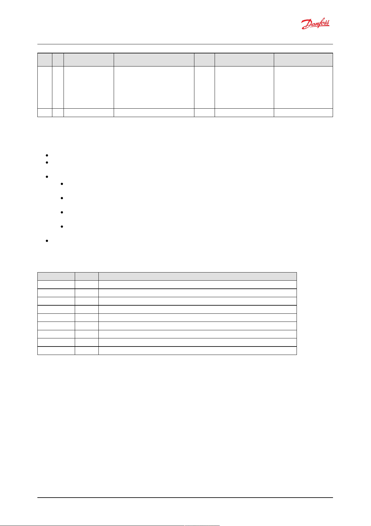
521051 6 Valve #12 solenoid current
failed
Valve number 12 (C4) solenoid failed to build
current as expected during solenoid current test.
Valve is disabled and adaptation algorithm is
used to allow pumping using the rest of the
working valves. Check for a disconnected harness
to the solenoid or another wiring issue. For
replacement parts or further help, contact
Danfoss.
INFO ERR_AE_521051_06_VC_1C4 ERR_OC_521051_06_VC_1C4
521051 7 Valve #12 pumping failed Not implemented in this version INFO ERR_AE_521051_07_VM_1C4 ERR_OC_521051_07_VM_1C4
SPN FMI Name Des criptio n Severity Ser vice Tool nam e for active
err or
Service T ool name for erro r
coun ter
8.3 Diagnosing faults
The following me thods can be used to diagnose a fault in the DDP096 pump and software:
View the Diagnostic LED color to establish the current status of the software.
Use the J1939 DM 1 and DM2 messages to ide ntify the active and previously active errors (see DM1 PGN
- active diag nostic trouble cod es and DM2 PGN - previously active diagnostics trouble codes sections).
In the PLUS+1® Service Tool:
check the DEVICE_MODE and DEVICE_STATE parameters to establish the current status of the
softw are.
check the currently active errors using the e rrors status pag e (or the active error parameters
dire ctly).
check the previously active errors using the counters on the error status page (or the error counter
parame ters directly).
use Commissioning mod e to allow limited operation with some errors active to diagnose system
issue s.
Follow the steps in the Commissioning and troubleshooting section of the Digital Displace ment® Pump
Gen 1 DDP096 and DPC12 Technical Information.
8.3.1 Diagnostic LED
Colo r Blink rate M eaning
Magenta Continuous Device is in boot-loader mode after "Recover ECU" function used in PLUS+1 Service Tool
Magenta blinking 1.5 Hz Device is in boot-loader mode because no valid application software was found
Blue blinking Fast irregular Device is downloading application software
Yellow blinking 1.5 Hz Device is in commissionin g mode
Yellow Continuou s Device is either waiting for DM13 message to enable the pump, in initialization state directly after power up, or in disabled state
Green Continuous Device is in active state
Red Continuous Device is in fault or fault hold state
Red blin king 1.5 Hz J1939 address claim error, CAN bus will not operate
Alternating red/green 1.5 Hz Device is in limp home mode and there is no severe error
Software Manual
Digital Displacement® Pump Software Version 2.7.1
29 | © Danfoss | February 2022 BC404560709540en-000102
Page 30
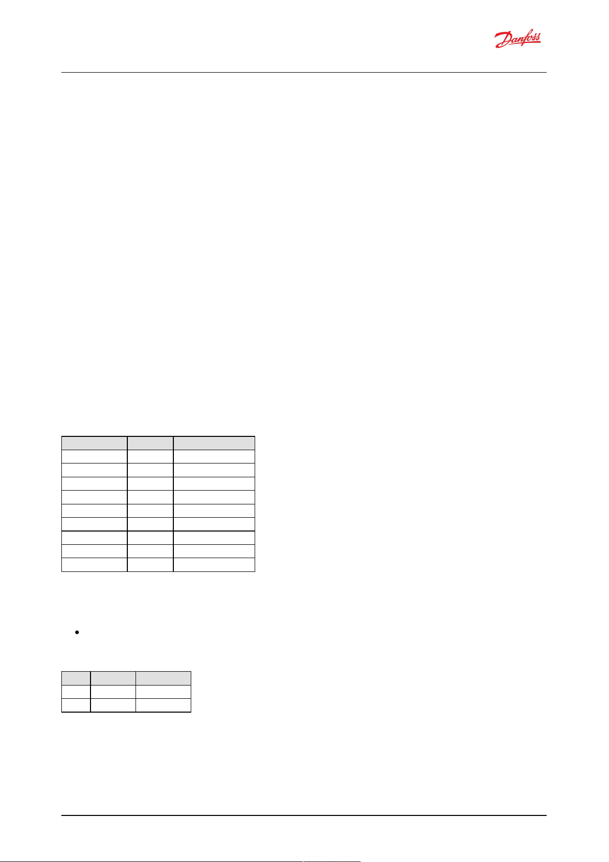
9 J1939 CAN protocol
The DDP096 softw are on the DPC12 can be commanded dynamically during use w ith a system controller,
testing application or other CAN bus-capable device. The softw are also reports the current operating status
and its error signals over the bus.
The protocol used is based on the automotive SAE J1939 protocol which is transmitted over a standard CAN
bus connection. This manual does not aim to describe all of the features of J1939. How eve r, it is possible to
control the p ump by sending standard CAN frames (w ith 29-b it IDs) formatted to match the J1939 protocol
implementation. Ple ase refer to SAE publications or contact your Danfoss rep rese ntative for further advice.
Two important concepts for the transmission and recep tion of J1939 messaged are Paramete r Group
Numbers (PGNs), which identify the purpose and format of a particular message containing data, and Suspe ct
Parameter Numbers (SPNs), w hich identify particular sig nals or parameters contained within a message. The
J1939 standard specifies many PGNs and SPNs and le aves space for manufacturers to spe cify the ir own when
neede d. The standard also uses the term Diag nostic Trouble Codes (DTCs), which represent an error in the
system.
CAN messages are limited to eight data bytes. When data longer than this is sent, a multi-packet message is
sent using a mechanism defined in the J1939 stand ard. Typically the DDP096 software uses a Broadcast
Announce M essage (BAM) session when required.
9.1 Address scheme
Each device on a J1939 netw ork must be uniquely ad dressable to be able to send and receive message s. This
is achieved through use of a J1939 Name to uniquely identify the function of a device on the network and an
addre ss give n to each device which is used during the communications.
The fields of the J1939 Name assigned to the controller are show n in the table below .
J193 9 Name field Length ( bits) V alue
Arbitrary address bit 1 0
Industry group 3 3
Vehicle system instance 4 0
Vehicle system 7 0
Function 8 255
Function instance 5 Set by FUN_ECU_INSTANCE
ECU instance 3 Set by FUN_ECU_INSTANCE
Manufacturer code 11 57
Identity number 21 200200
Whe n using more than one DPC12 controller on the ne twork, a unique FUN_ECU_INSTANCE value must be
assig ned to each controller in order to ensure that each device has a unique J1939 Name and can therefore
be assigned an address on the J1939 netw ork.
FUN_ECU_INSTANCE: This parameter sets the ECU Instance and Function Instance values which form p art
of the J1939 Name of the device, allowing the use r to give each d evice a unique name in the system.
Any value which is not shared with another DPC12 controller will allow the system to operate correctly.
Bit No. V alue/ran ge Descr iption
3 bits 0..2 0..7 ECU Instance
5 bits 3..7 0..31 Functional Instance
A g roup of controllers are often required to perform a specific function in a system. In comp le x systems, the
same function may be implemented more than once. To identify which instance of a function a particular
controller belong s to, the Functional Instance is used. The ECU Instance is used to identify a particular
controller within an instance of a function. Conside r, for example, a braking system which has two controllers each controller would have a different ECU Instance , but the same Functional Instance as b oth controllers are
required to perform the braking function. Now, consider that this brake syste m is replicated on each wheel of
Software Manual
Digital Displacement® Pump Software Version 2.7.1
30 | © Danfoss | February 2022 BC404560709540en-000102
Page 31
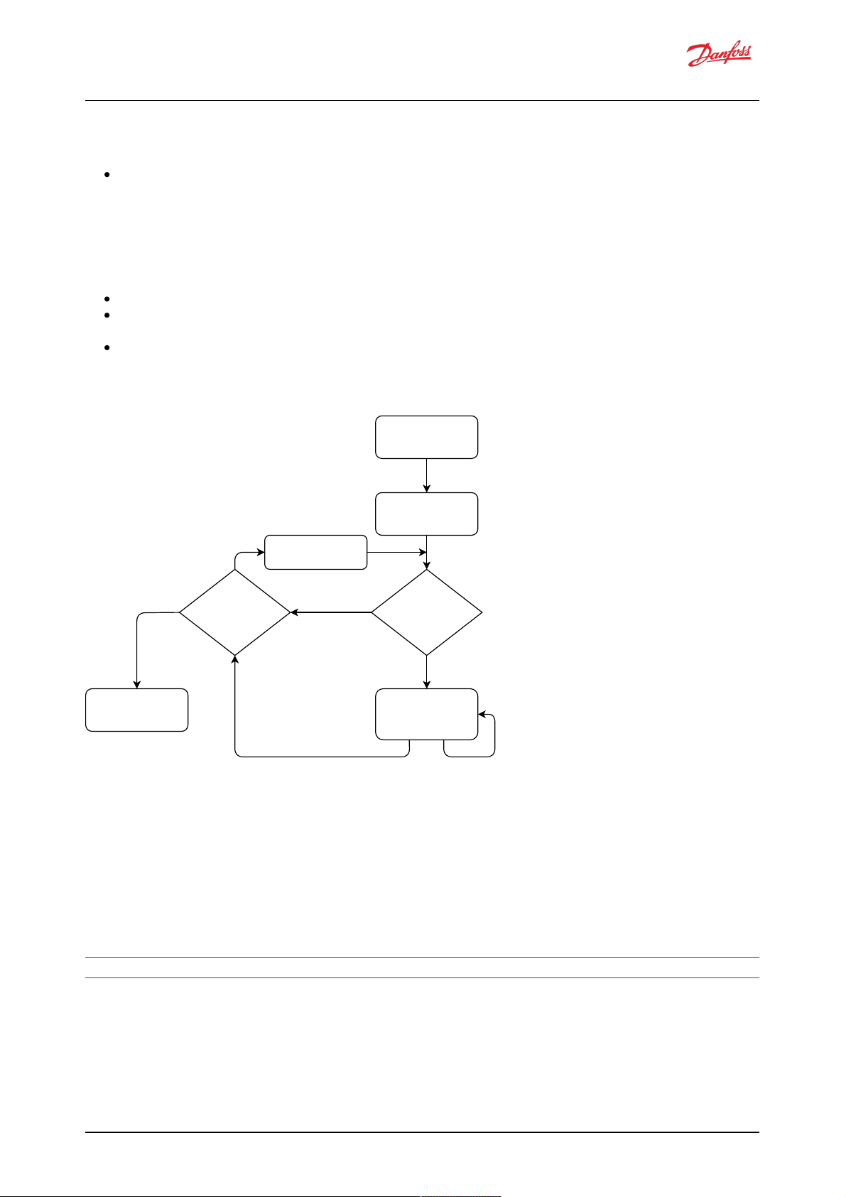
a vehicle - the controllers on each wheel would be able to keep their existing ECU Instance values, how ever
the Functional Instance values w ould have to be unique to each w heel.
NODE_ID: This parameter sets the address w hich the DPC12 controller will attempt to claim on start-up.
This value must not be in use by any other DPC12 controller, and should also not be used b y any other
device on the bus. Note this parameter is also used by the PLUS+1® Se rvice Tool to identify the DPC12
controller.
On start-up the DPC12 controller will initiate an add ress claim procedure where it attempts to claim the
addre ss configured by the NODE_ID parame ter. The re sult of the claim proced ure w ill be one of the follow ing:
The address is claimed successfully and the controlle r starts communication.
The address cannot be claimed because a device with a higher-priority J1939 Name has claimed this
addre ss. An address claim failure error will be raised.
Another device on the network with the same J1939 Name is d etected, usually another DPC12 with the
same value of the FUN_ECU_INSTANCE parameter. A name conflict error will be raised.
An outline of this procedure is show n in this flowchart:
Power on DPC12
No contending address
claim received
Wait 250ms
for address claim
contention
Send address claim
'Controller
J1939 address claim
failure' error raised
Receive a
contending
address claim
Address claimed
Send / receive
normal message
traffic
Is
contenders NAME
less than mine?
Yes
No
Reclaim current
address
Received contender address claim
Received
request for
address claim
For the full add ress claim procedure re fer to SAE J1939 standard or contact your Danfoss re presentative .
9.2 PGN priorities
The three-bit priority field in J1939 is inte nde d to give the syste m d esigner the ability to prioritize messages
on the bus, with a lower number giving the message a highe r p riority. In the current implementation the
messages received by the DPC12 controller w ill only be read correctly if a spe cific priority (3) is used. This
be havior w ill be changed in a future softw are upd ate to give fle xibility in the p riorities used.
All received J1939 priorities must match the me ssage information table to b e received correctly.
9.3 SLOTs
J1939 uses standard SLOTs (scaling, limit, offset and transfer function) to represent physical quantitie s as data
in the J1939 CAN frames. As well as using standard SLOTs, the DDP096 softw are uses several custom SLOTs
where a standard SLOT w as not available. These SLOTs are named with a DD prefix. Details of e ach SLOT used
in the softw are are given in the table be low. Full details can be found in the J1939 Digital Anne x, available
from the SAE.
Software Manual
Digital Displacement® Pump Software Version 2.7.1
31 | © Danfoss | February 2022 BC404560709540en-000102
Page 32

SLOT nam e SLOT type Scaling Ran ge O ffset Len gth
SAEbs04 Bit field 16 states/4 bit 0 to 15 0 4 bits
SAEbs08 Bit field 256 states/8 bit 0 to 255 0 8 bits
SAEbm16 Bit mapped 16 bit bit-mapped bit-mapped 0 16 bits
SAEpc11 Percent, position/level 0.005%/bit -150 to 171.275% -150 % 2 bytes
SAEpr08 Pressure 2 kPa/bit 0 to 128,510 kPa 0 2 bytes
SAEpw08 Power, real 0.05 kW/bit -1600 to 1612.75 kW -1600 kW 2 bytes
SAEtp01 Temperature 1 °C/bit -40 to 210 °C -40 °C 1 byte
SAEvr07 Velocity, rotational 1 rpm per bit -32127 to 32128 rpm -32127 rpm 2 bytes
DDtq01 Torque 0.2 Nm/bit -6400 to 6451 Nm -6400 Nm 2 bytes
DDfl02 Flow rate 0.05 L/min/bit -1600 to 1612.75 L/min -1600 L/min 2 bytes
Whe re a SLOT used in J1939 communication has highe r resolution than the correspond ing PLUS+1® Service
Tool paramete r, the value will be truncated (rounded-down) to match the parameter resolution. If a differe nt
rounding method is desired the system controller code should include the rounding to the parameter's
precision before sending the value over J1939. This behavior w ill b e changed in a future softw are update to
allow the full resolution of the SLOTs to be used for more precise control.
9.4 Diagnostic messages
Several stand ard J1939 diagnostic me ssag es are implemente d in the controller.
Each diagnostic messag e is detailed in the following sections. Example sequences of J1939 message frames in
diffe rent circumstances are given for each diagnostic messag e.
In all example me ssage id entifiers ("msg ID"s) the system controller node ID in hexad ecimal is indicate d by yy
and the DPC12 node ID is indicated by zz. Following the J1939 standard, the destination addre ss for any
message can be set to 0xFF rather than a specific DPC12 node ID to send a messag e to all node s in the
system.
9.4.1 DM1 PGN - active diagnostic trouble codes
The DM1 PGN communicates the details of the errors (DTCs) which are curre ntly active in the DDP096
softw are.
If more than one e rror is active, a BAM session is use d to communicate the active errors. The maximum
number of errors that can be sent by BAM session is 30. If there are 29 active errors at the same time, the "Too
many errors to handle by J1939" error is automatically raised, w hich is the 30th error in the BAM session.
9.4.1.1 Message information
Whe n only one error is active a single me ssage is sent w ith the following information:
Name DM1
Priority 6
Data page 0
PDU format 0xFE
PDU specific 0xCA
Source address DPC12 node ID (zz)
Full message ID 0x18FECAzz
DLC (length) 8
Direction Transmitted by DPC12
Occurrence Periodic — every 1s or on occurrence or disappearance
of error
Software Manual
Digital Displacement® Pump Software Version 2.7.1
32 | © Danfoss | February 2022 BC404560709540en-000102
Page 33

9.4.1.2 Message data
Whe n only one error is active a single me ssage is sent w ith the following format:
Byte no. Enco ding Value/r ange Description
0 U8
0x04
0x10
Lamp status:
Amber lamp (for warning and info errors)
Red lamp (for critical and severe errors)
1 U8 0xFF Flash status
2 U8 0x00...0xFF LSB of SPN (suspect part number)
3 U8 0x00...0xFF Next LSB of SPN
5 bits 0...4 0x00...0x1F FMI (failure mode indicator)
3 bits 5...7 0x00...0x07 MSB of SPN
5 bits 0...6 0x00...0x7F Occurrence count
5 bit 7 0x00 Conversion method
6..7 All bits set to 1 Reserved
9.4.1.3 DM1 example scenarios
The following scenarios describe the DM1 transmissions based on specific situations.
9.4.1.3.1 Scenario 1 - single active error
If there is only one active error in the system, the DDP096 software on the DPC12 will send out the DM1
message as follows. This indicates that an error with an SPN of 0x07F312 (520978) and an FMI of 0x09 (9) with
warning severity is active, and has occurred three times.
Typ e Msg ID DLC Byte0 Byte1 B yte2 Byte3 Byte4 Byte5 Byte6 Byte7
DM1 0x18FECAzz 8 0x04 0xFF 0x12 0xF3 0xE9 0x03 0xFF 0xFF
8 Lamp status Flash status SPN1 SPN2 SPN3/FMI OC Reserved Reserved
9.4.1.3.2 Scenario 2 - no active errors
If there are no active e rrors in the system, the DDP096 software on the DPC12 will send out the DM1 message
as follow s:
Typ e Msg ID DLC Byte0 Byte1 B yte2 Byte3 Byte4 Byte5 Byte6 Byte7
DM1 0x18FECAzz 8 0x00 0xFF 0x00 0x00 0x00 0x00 0xFF 0xFF
8 Lamp status Flash status SPN1 SPN2 SPN3/FMI OC Reserved Reserved
9.4.1.3.3 Scenario 3 - more than one active error
If there is more than one active error in the system, the DDP096 software on the DPC12 will send out DM1 in
the format of BAM messages as follow s. In this example the follow ing errors are active:
First error: SPN 0x0000A8, FMI 0x03 of warning level w ith one occurrence,
Second error: SPN 0x07F183, FMI 0x02 of critical le vel w ith six occurrences,
Third error: SPN 0x07F308, FMI 0x0B of critical level with six occurrences,
Fourth error: SPN 0x07F30F, FM I 0x10 of warning level w ith eight occurrences.
Software Manual
Digital Displacement® Pump Software Version 2.7.1
33 | © Danfoss | February 2022 BC404560709540en-000102
Page 34

Typ e Msg ID DLC Byte0 Byte1 B yte2 Byte3 Byte4 Byte5 Byte6 Byte7
BAM 0x1CECFFzz 8 0x20 0x12 0x00 0x03 0xFF 0xCA 0xFE 0x00
BAM No. of bytes, LSB No. of bytes, MSB No of packets Reserved DM1 PGN Byte0 DM1 PGN Byte1 DM1 PGN Byte2
DT1 0x1CEBFFzz 8 0x01 0x10 0xFF 0xA8 0x00 0x03 0x01 0x83
Seq Lamp status Flash status Error code 1,
SPN1
Error code 1,
SPN2
Error code 1,
SPN3/FMI
Error code 1, OC Error code 2,
SPN1
DT2 0x1CEBFFzz 8 0x02 0xF1 0xE2 0x06 0x08 0xF3 0xEB 0x06
Seq Error code 2,
SPN2
Error code 2,
SPN3/FMI
Error code 2, OC Error code 3,
SPN1
Error code 3,
SPN2
Error code 3,
SPN3/FMI
Error code 3, OC
DT3 0x1CEBFFzz 8 0x03 0x0F 0xF3 0xF0 0x08 0xFF 0xFF 0xFF
Seq Error code 4,
SPN1
Error code 4,
SPN2
Error code 4,
SPN3/FMI
Error code 4, OC Reserved Reserved Reserved
9.4.2 DM2 PGN - previously active diagnostics trouble codes
The DM2 PGN communicates the details of the errors (DTCs) which are w ere previously active in the DDP096
softw are.
The DM2 message is transmitte d by the DPC12 only if it is re que ste d by another device on the CAN bus using
a request PGN message specifying PGN 0xFECB. See Request PGN section for more details.
If more than one e rror is active, a BAM session is use d to communicate the active errors. The maximum
number of errors that can be sent by BAM session is 30. If there are 29 active errors at the same time, the "Too
many errors to handle by J1939" error is automatically raised, w hich is the 30th error in the BAM session.
9.4.2.1 Message information
Whe n only one error w as previously active a single me ssage is sent w ith the following information:
Name DM2
Priority 6
Data page 0
PDU format 0xFE
PDU specific 0xCB
Source address DPC12 node ID (zz)
Full message ID 0x18FECBzz
DLC (length) 8
Direction Transmitted by DPC12
Occurrence On request
9.4.2.2 Message data
Whe n only one error w as previously active a single me ssage is sent w ith the following format:
Byte No. Enco ding Value/Ran ge Descr iption
0 U8
0x00
0x04
0x10
Lamp status:
DEFAULT (no error)
AMBER LAMP (for warning and info errors)
RED LAMP (for critical and severe errors)
1 U8 0xFF Flash status
2 U8 0x00...0xFF LSB of SPN (Suspect Parameter Number)
3 U8 0x00...0xFF Next LSB of SPN
4 Bits 0...4 0x00...0x1F FMI (Failure Mode Indicator)
Bits 5...7 0x00...0x07 MSB of SPN
5 Bits 0...6 0x00...0x7F Occurrence Count
Bit 7 0x00 Conversion Method
6...7 - All bits set to 1 Reserved
Software Manual
Digital Displacement® Pump Software Version 2.7.1
34 | © Danfoss | February 2022 BC404560709540en-000102
Page 35

9.4.2.3 DM2 example scenarios
The following scenarios describe the DM2 transmissions based on specific situations.
Send request for DM2
Typ e M sg ID DLC B yte0 Byte1 Byte2
Request 0x18EAzzyy 3 0xCB 0xFE 0x00
9.4.2.3.1 Scenario 1 - single previously active error
If there is only one previously active error in the system, the DDP096 software on the DPC12 w ill send out the
DM2 messag e as follows. This indicates that an error with an SPN of 0x07F30D and an FMI of 0x11 w ith
warning severity was previously active in the syste m and occurred once.
Typ e Msg ID DLC Byte0 Byte1 B yte2 Byte3 Byte4 Byte5 Byte6 Byte7
DM2 0x18FECBzz 8 0x04 0xFF 0x0D 0xF3 0xF1 0x01 0xFF 0xFF
8 Lamp status Flash status SPN1 SPN2 SPN3/FMI OC Reserved Reserved
9.4.2.3.2 Scenario 2 - no previously active errors
If no previously active errors are present in the system, the DDP096 softw are on the DPC12 w ill send out the
DM2 messag e as follows:
Typ e Msg ID DLC Byte0 Byte1 B yte2 Byte3 Byte4 Byte5 Byte6 Byte7
DM2 0x18FECBzz 8 0x00 0xFF 0x00 0x00 0x00 0x00 0xFF 0xFF
8 Lamp status Flash status SPN1 SPN2 SPN3/FMI OC Reserved Reserved
9.4.2.3.3 Scenario 3 - more than one previously active error
If there is more than one previously active e rror present in the system, the DDP096 software on the DPC12
will send out the DM 2 in the format of BAM messages. In this example the following errors were pre viously
active.
First previously active e rror: SPN 0x07F183, FM I 0x02 of critical level w ith six occurrences.
Second previously active error: SPN 0x07F308, FMI 0x0B of critical level with six occurrence s.
Third previously active error: SPN 0x0000A8, FMI 0x03 of warning leve l with one occurrence.
Fourth previously active e rror: SPN 0x07F30F, FM I 0x10 of warning le vel with six occurrences.
Typ e Msg ID DLC Byte0 Byte1 B yte2 Byte3 Byte4 Byte5 Byte6 Byte7
BAM 0x1CECFFzz 8 0x20 0x12 0x00 0x03 0xFF 0xCB 0xFE 0x00
BAM No. of bytes, LSB No. of bytes, MSB No. of packets Reserved DM2 PGN Byte0 DM2 PGN Byte1 DM2 PGN Byte2
DT1 0x1CEBFFzz 8 0x01 0x00 0xFF 0x83 0xF1 0xE2 0x06 0x08
Seq Lamp status Flash status Error code 1,
SPN1
Error code 1,
SPN2
Error code 1,
SPN3/FMI
Error code 1, OC Error code 2,
SPN1
DT2 0x1CEBFFzz 8 0x02 0xF3 0xEB 0x06 0xA8 0x00 0x03 0x01
Seq Error code 2,
SPN2
Error code 2,
SPN3/FMI
Error code 2, OC Error code 3,
SPN1
Error code 3,
SPN2
Error code 3,
SPN3/FMI
Error code 3, OC
DT3 0x1CEBFFzz 8 0x03 0x0F 0xF3 0xF0 0x06 0xFF 0xFF 0xFF
Seq Error code 4,
SPN1
Error code 4,
SPN2
Error code 4,
SPN3/FMI
Error code 4, OC Reserved Reserved Reserved
The lamp status indicate s the current active error status. In this example there are no currently active
errors, so the value is 0x00.
Software Manual
Digital Displacement® Pump Software Version 2.7.1
35 | © Danfoss | February 2022 BC404560709540en-000102
Page 36

9.4.2.3.4 Scenario 4 - BAM session unavailable
If there is more than one previously active e rror present in the system and BAM session is unavailable (may be
busy w ith transmission of DM1/DM2) then the DDP096 software on the DPC12 will send out a busy
acknowledgme nt message glob ally as follows:
Typ e Msg ID DLC Byte0 Byte1 B yte2 Byte3 Byte4 Byte5 Byte6 Byte7
Ack 0x18E8FFzz 8 0x02 0x00 0xFF 0xFF 0xyy 0xCB 0xFE 0x00
BAM Busy 0x00 Reserved Reserved Address busy
Ack
Requested PGN
Byte 0
Requested PGN
Byte 1
Requested PGN
Byte 2
9.4.3 DM3 PGN - diagnostics data clear of previously active DTCs
The system controller, or other device on the CAN bus, can send the DM3 message to clear the occurrence
counters for all errors (equivalent to setting the RESET_ERR_CNTR_CMD paramete r). Each time the command is
issue d, up to 29 error counters are reset. Issue command thre e times to ensure all error counters are reset.
DM3 is sent to the DPC12 controller by send ing a Request PGN with the DM3 PGN, 65228, in the req uested
PGN fie ld .
On receiving the DM3 request, the DPC12 will send an Acknow ledgment PGN ind icating one of the following
responses:
positive acknow ledgement - the action w as successful.
acce ss denied - the action could not be processed as there was already a diagnostics data cle ar in
prog ress.
9.4.3.1 Message information
See the Acknow ledgment PGN se ction for details of the PGN sent in reply to a DM3 message.
9.4.3.2 DM3 example scenarios
The following scenarios describe the DM3 transmissions based on specific situations.
Send request for DM3
Typ e M sg ID DLC B yte0 Byte1 Byte2
Request 0x18EAzzyy 3 0xCC 0xFE 0x00
9.4.3.2.1 Scenario 1 - positive acknowledgement of DM3
After clearing the error log history the DPC12 will send positive acknowledgme nt as:
Typ e Msg ID DLC Byte0 Byte1 B yte2 Byte3 Byte4 Byte5 Byte6 Byte7
Ack 0x18E8FFzz 8 0x00 0x00 0xFF 0xFF 0xyy 0xCC 0xFE 0x00
9.4.3.2.2 Scenario 2 - request denied, controller busy
Send a request for DM3 before the DDP096 softw are on the DPC12 has finished processing the previous DM 3
request.
DPC12 w ill send busy acknow ledgment as follows:
Typ e Msg ID DLC Byte0 Byte1 B yte2 Byte3 Byte4 Byte5 Byte6 Byte7
Ack 0x18E8FFzz 8 0x02 0x00 0xFF 0xFF 0xyy 0xCC 0xFE 0x00
Software Manual
Digital Displacement® Pump Software Version 2.7.1
36 | © Danfoss | February 2022 BC404560709540en-000102
Page 37

9.4.4 DM11 PGN - diagnostics data clear of active DTCs
The system controller, or other device on the CAN bus, can send the DM11 message to request that the
DDP096 softw are resets its fault status and moves from the fault hold state to the d isabled or active state.
This transition may not be allowed depending on the severity of previously active errors. Please see the Error
hand ler states section for more details.
DM11 is sent to the DPC12 controller by sending a Request PGN with the DM 11 PGN, 65235, in the requested
PGN fie ld .
On receiving the DM11 request, the DPC12 will send an Acknowle dgment PGN indicating that either return
positive acknow ledgement - the action w as successful and the fault was cleared.
negative acknowledgement - the action w as not completed as the e rror hand le r was not in the fault
hold state or there w as a p reviously active severe error.
9.4.4.1 Message information
See the Acknow ledgment PGN se ction for details of the PGN sent in reply to a DM11 message.
9.4.4.2 DM11 example scenarios
The following scenarios describe the DM11 transmissions based on spe cific situations.
Send request for DM11
Typ e M sg ID DLC B yte0 Byte1 Byte2
Request 0x18EAyyzz 3 0xD3 0xFE 0x00
9.4.4.2.1 Scenario 1 - no severe errors are present
No severe errors are present in the DPC12.
As there are no severe level e rrors present, DPC12 will send positive re sponse, as follows:
Typ e Msg ID DLC Byte0 Byte1 B yte2 Byte3 Byte4 Byte5 Byte6 Byte7
Ack 0x18E8FFzz 8 0x00 0x00 0xFF 0xFF 0xyy 0xD3 0xFE 0x00
9.4.4.2.2 Scenario 2 - severe errors are present
Severe errors are p rese nt in the DPC12.
As there are some severe errors in the syste m, the DPC12 will send ne gative response, as follows:
Typ e Msg ID DLC Byte0 Byte1 B yte2 Byte3 Byte4 Byte5 Byte6 Byte7
Ack 0x18E8FFzz 8 0x01 0x00 0xFF 0xFF 0xyy 0xD3 0xFE 0x00
9.4.5 DM13 PGN - ignore all info and warning errors until DM13 is received
Enab ling the SUPPORT_DM13_PGN parameter w ill cause the DPC12 to ignore all info and warning severity
errors, not communicate them on the CAN b us, and kee p the DPC12 in the disabled state (and therefore not
provide flow) afte r the controller is pow ere d on until it re ceive s the DM13 message from a system controller.
Whe n the parameter is disabled the DPC12 transitions immediately to the active state unless there are any
non-info le vel errors, in which case a fault w ill b e declared immediately.
If parame ter SUPPORT_DM13_PGN is set to 1, after pow er-on the DPC12 w ill process only critical and severe
active errors and communicate the m on the CAN bus. Active info and w arning errors w ill be ignored. After
receiving 'Start Diagnostic DM13' the DPC12 will return to normal error hand ling state and communicate all
Software Manual
Digital Displacement® Pump Software Version 2.7.1
37 | © Danfoss | February 2022 BC404560709540en-000102
Page 38

active errors on the CAN bus. No response to the DM 13 message w ill be sent by the DPC12.
If parame ter SUPPORT_DM13_PGN is set to 0, the DPC12 will send a negative acknowledgment, see the
Acknowledgme nt PGN section. All active errors will be processed and communicated on the CAN bus as
usual.
9.4.5.1 Message information
Name DM13
Priority 6
Data page 0
PDU format 0xDF
PDU specific DPC12 node ID (zz)
Source address System controller node ID (yy)
Full message ID 0x18DFzzyy
DLC (length) 8
Direction Received by DPC12
Occurrence As needed
9.4.5.2 Message data
Byte No. Enco ding Value/Ran ge Descr iption
0 Bits 0...1 Network type J1939 network #1, primary vehicle network
0 Reserved
1 Start Broadcast
2 Reserved
3 No Action
Bits 2...7 Set all bits to 1 Reserved
1...7 U8 Set all bits to 1 Reserved
DPC12 is assumed to be part of 'J1939 netw ork #1, primary ve hicle netw ork' for the DM 13 message setup.
9.4.5.3 DM13 example scenarios
The following scenarios describe the DM13 transmissions based on spe cific situations.
9.4.5.3.1 Scenario 1 - DM13 support enabled
SUPPORT_DM13_PGN is set to 1 and the controller has just bee n powered on and is in the disabled state.
The system controller sends the DM 13 message to the DPC12.
Typ e Msg ID DLC Byte0 Byte1 B yte2 Byte3 Byte4 Byte5 Byte6 Byte7
DM13 0x18DFFFyy 8 0xFD 0xFF 0xFF 0xFF 0xFF 0xFF 0xFF 0xFF
The DPC12 software w ill leave the disab le d state . No reply message will be sent.
9.4.5.3.2 Scenario 2 - DM13 support disabled
SUPPORT_DM13_PGN is set to 0.
The system controller sends the DM 13 message to the DPC12.
Software Manual
Digital Displacement® Pump Software Version 2.7.1
38 | © Danfoss | February 2022 BC404560709540en-000102
Page 39

Typ e Msg ID DLC Byte0 Byte1 B yte2 Byte3 Byte4 Byte5 Byte6 Byte7
DM13 0x18DFFFyy 8 0xFD 0xFF 0xFF 0xFF 0xFF 0xFF 0xFF 0xFF
As support for the DM13 message has been d isab le d, the DPC12 will se nd negative acknow ledgment.
Typ e Msg ID DLC Byte0 Byte1 B yte2 Byte3 Byte4 Byte5 Byte6 Byte7
Ack 0x18E8FFzz 8 0x01 0x00 0xFF 0xFF 0xyy 0xFF 0xDF 0x00
9.4.6 Request PGN
A request PGN message is used to request a particular value be returned or action started. The me ssage data
contains only the numbe r of the PGN req uested .
9.4.6.1 Message information
Name Request PG N
Priority 6
Data page 0
PDU format 0xEA
PDU specific DPC12 node ID (zz)
Source address System controller node ID (yy)
Full message ID 0x18EAzzyy
DLC (length) 3
Direction Received by DPC12
Occurrence As needed
9.4.6.2 Message data
Byte no. Enco ding Value/r ange Description
0...2 U24 0x01FFFF: valid Requested PGN
9.4.7 Acknowledgment PGN
The DDP096 softw are may transmit an acknowledgement frame after rece iving some request messages
rathe r than a frame containing data, for instance when there is no data response required or w hen a response
cannot be given.
9.4.7.1 Message information
Name Ackn owledgment PGN
Priority 6
Data page 0
PDU format 0xE8
PDU specific 0xFF
Source address DPC12 node ID (zz)
Full message ID 0x18E8FFzz
DLC (length) 8
Direction Transmitted by DPC12
Occurrence As needed
Software Manual
Digital Displacement® Pump Software Version 2.7.1
39 | © Danfoss | February 2022 BC404560709540en-000102
Page 40
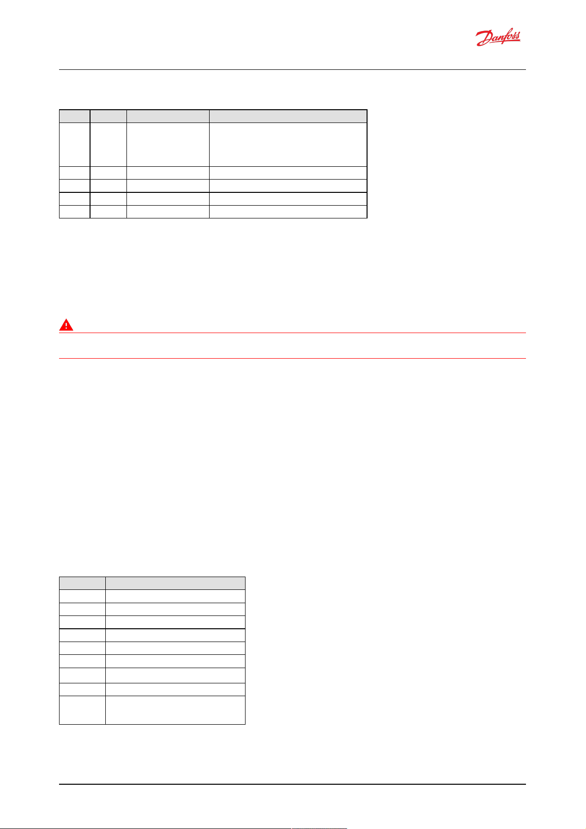
9.4.7.2 Message data
Byte no. Enco ding Value/r ange Description
0 U8 0x00: Positive
acknowledgement
0x01: Negative
acknowledgement
0x02: Access denied
Control byte
1 U8 0 Group Function Value (not used)
2...3 Set all bits to 1 Reserved
4 U8 0x00-0xFF Destination Address
5...7 U24 0x01FFFF:valid Requested PGN
9.5 Manufacturer specific PGNs
The DDP096 softw are uses several manufacturer sp ecific messages to control and re port Dig ital
Displacement® Pump functionality. These messages use the J1939 proprie tary PGNs which can operate
alongside all standardise d J1939 PGNs. The messag es used are desig ne d to op erate alongside other Danfoss
prod ucts, howeve r e quipment manufactured by other manufacture rs may use conflicting de finitions for the
prop rietary PGNs.
Warning
Danfoss manufacture r specific PGNs may conflict w ith other devices on the CAN bus. The system designer
must check for compatibility.
The PGNs are de fined in the sections below .
9.5.1 Control PGNs
The DDP096 softw are can receive control messages from a system controlle r on the CAN bus to allow the
hydraulic outputs to be controlled dynamically. Whether the data in the me ssage is used or not dep ends on
the value of the source parame ter corresponding to the control refe rence or limit in the messag e. Se e Control
config uration section for more details.
9.5.1.1 Pump setup A
The pump setup A message allow s the system controller to control whole pump feature s in the softw are. The
message must be sent by the system controller if the pump ing enable source or service configuration inde x
sourc e are set to J1939.
9.5.1.1.1 Message information
Name Pump setu p A
Priority 3
Data page 0
PDU format 0xEF
PDU specific DPC12 node ID (zz)
Source address System controller node ID (yy)
Full message ID 0x0CEFzzyy
DLC (length) 8
Direction Received by DPC12
Occurrence Repeated when PUMPING_ENABLE_SRC or
SERV_CONF_INDEX_SRC set to J1939.
Timeout 300 ms.
Software Manual
Digital Displacement® Pump Software Version 2.7.1
40 | © Danfoss | February 2022 BC404560709540en-000102
Page 41

9.5.1.1.2 Message data
Byte no. Enco ding Value/r ange Description
0...1 0xDD00 Message ID
2...3 SAEbm16 0x0000...0x00FF: Enable bitmap
0x0100...0xFDFF: Reserved
0xFExx: Error indicator
0xFFxx: Not used/not
requested
Pumping enable per service.
Service 1 by bit 0, Service 2 by bit 1. Set other bits to 0.
Also see PUMPING_ENABLE parameter.
4 SAEbs08 0...2: Index for pumplet
combination
4...253: Reserved
254: Error indicator
255: Not used/not requested
Service configuration index, see SERV_CONF_INDEX
parameter
5...7 All bits set to 1 Reserved
9.5.1.2 Displacement reference A
The d isplacement reference A messag e allows the displacement re ference to seve ral service s to be sent in
displace ment mode. The messag e must be sent by the system controller if the DDP096 software is se t up for
displace ment control over J1939 on eithe r service (see "Occurrence" in the table below).
9.5.1.2.1 Message information
Name Displacement r eference A
Priority 3
Data page 0
PDU format 0xEF
PDU specific DPC12 node ID (zz)
Source address System controller node ID (yy)
Full message ID 0x0CEFzzyy
DLC (length) 8
Direction Received by DPC12
Occurrence Repeated when either CONTROL_MODE_S1 or
CONTROL_MODE_S2 are displacement control and its
source (CONTROL_REF_SRC_S1 or
CONTROL_REF_SRC_S2) is set to J1939.
Timeout 300 ms.
9.5.1.2.2 Message data
Byte no. Enco ding Value/r ange Description
0...1 0xDD10 Message ID
2...3 SAEpc11 0%...100%: Valid
0xFExx: Error indicator
0xFFxx: Not used/not
requested
Displacement reference for service 1, see DISP_REF_S1
parameter
4...5 SAEpc11 0%...100%: Valid
0xFExx: Error indicator
0xFFxx: Not used/not
requested
Displacement reference for service 2, see DISP_REF_S2
parameter
6...7 All bits set to 1 Reserved
9.5.1.3 Pressure reference A
The pressure reference A message allows the p ressure reference to several services to be sent in pressure
control mode. The me ssage must be sent by the system controlle r if the DDP096 software is set up for
pressure control over J1939 on either service (see "Occurrence" in the table below ).
Software Manual
Digital Displacement® Pump Software Version 2.7.1
41 | © Danfoss | February 2022 BC404560709540en-000102
Page 42
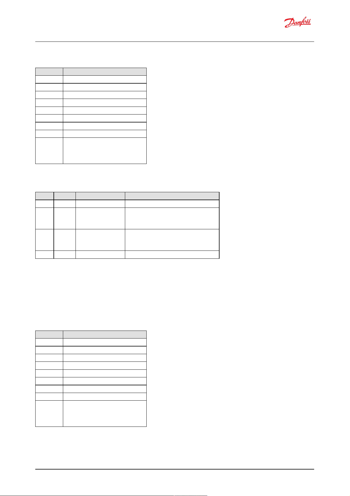
9.5.1.3.1 Message information
Name Pressu re refer ence A
Priority 3
Data page 0
PDU format 0xEF
PDU specific DPC12 node ID (zz)
Source address System controller node ID (yy)
Full message ID 0x0CEFzzyy
DLC (length) 8
Direction Received by DPC12
Occurrence Repeated when either CONTROL_MODE_S1 or
CONTROL_MODE_S2 are pressure control and its
source (CONTROL_REF_SRC_S1 or
CONTROL_REF_SRC_S2) is set to J1939.
Timeout 300 ms.
9.5.1.3.2 Message data
Byte no. Enco ding Value/r ange Description
0...1 0xDD13 Message ID
2...3 SAEpr08 0...42000 kPa (420 bar): Valid
0xFExx: Error indicator
0xFFxx: Not used/not
requested
Pressure reference for service 1, see PRESS_REF_S1
parameter
4...5 SAEpr08 0...42000 kPa (420 bar): Valid
0xFExx: Error indicator
0xFFxx: Not used/not
requested
Pressure reference for service 2, see PRESS_REF_S2
parameter
6...7 All bits set to 1 Reserved
9.5.1.4 Pressure margin reference A
The pressure margin re ference A message allows the pressure margin reference to se veral services to be sent
in load-sense mode. The me ssage must be sent by the system controller if the DDP096 softw are is se t up for
load-sense control ove r J1939 on either service (see "O ccurrence" in the table below ).
9.5.1.4.1 Message information
Name Pressu re marg in referen ce A
Priority 3
Data page 0
PDU format 0xEF
PDU specific DPC12 node ID (zz)
Source address System controller node ID (yy)
Full message ID 0x0CEFzzyy
DLC (length) 8
Direction Received by DPC12
Occurrence Repeated when either CONTROL_MODE_S1 or
CONTROL_MODE_S2 are load-sense and its source
(CONTROL_REF_SRC_S1 or
CONTROL_REF_SRC_S2) is set to J1939.
Timeout 300 ms.
Software Manual
Digital Displacement® Pump Software Version 2.7.1
42 | © Danfoss | February 2022 BC404560709540en-000102
Page 43
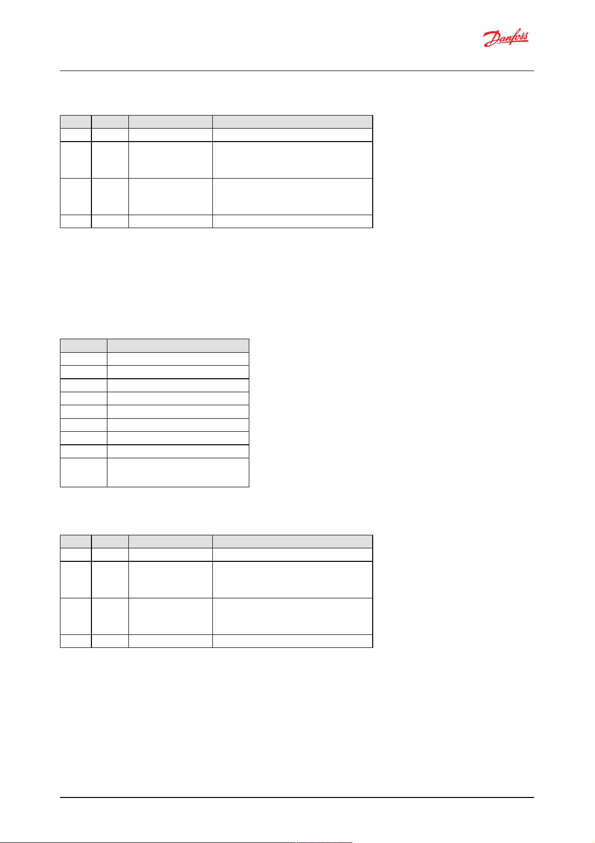
9.5.1.4.2 Message data
Byte no. Enco ding Value/r ange Description
0...1 0xDD16 Message ID
2...3 SAEpr08 0...10000 kPa (100 bar): Valid
0xFExx: Error indicator
0xFFxx: Not used/not
requested
Pressure margin reference for service 1, see
PRESS_MARGIN_REF_S1 parameter
4...5 SAEpr08 0...10000 kPa (100 bar): Valid
0xFExx: Error indicator
0xFFxx: Not used/not
requested
Pressure margin reference for service 2, see
PRESS_MARGIN_REF_S2 parameter
6...7 All bits set to 1 Reserved
9.5.1.5 Torque limit A
The torque limit A message allow s the torque limit to several services to be sent. The message must be sent
by the system controller if one of the torque limit source paramete rs is set to J1939.
9.5.1.5.1 Message information
Name Tor que limit A
Priority 3
Data page 0
PDU format 0xEF
PDU specific DPC12 node ID (zz)
Source address System controller node ID (yy)
Full message ID 0x0CEFzzyy
DLC (length) 8
Direction Received by DPC12
Occurrence Repeated when either TRQ_LIM_SRC_S1 or
TRQ_LIM_SRC_S2 are set to J1939.
Timeout 300 ms.
9.5.1.5.2 Message data
Byte no. Enco ding Value/r ange Description
0...1 0xDD40 Message ID
2...3 DDtq01 0...1500 Nm: Valid
0xFExx: Error indicator
0xFFxx: Not used/not
requested
Torque limit for service 1, see TRQ_LIM_S1 parameter
4...5 DDtq01 0...1500 Nm: Valid
0xFExx: Error indicator
0xFFxx: Not used/not
requested
Torque limit for service 2, see TRQ_LIM_S2 parameter
6...7 All bits set to 1 Reserved
9.5.1.6 Flow limit A
The flow limit A me ssag e allows the flow limit to seve ral service s to be sent. The message must be sent by the
system controller if one of the flow limit source parameters is set to J1939.
Software Manual
Digital Displacement® Pump Software Version 2.7.1
43 | © Danfoss | February 2022 BC404560709540en-000102
Page 44

9.5.1.6.1 Message information
Name Flow limit A
Priority 3
Data page 0
PDU format 0xEF
PDU specific DPC12 node ID (zz)
Source address System controller node ID (yy)
Full message ID 0x0CEFzzyy
DLC (length) 8
Direction Received by DPC12
Occurrence Repeated when either FLOW_LIM_SRC_S1 or
FLOW_LIM_SRC_S2 are set to J1939.
Timeout 300 ms.
9.5.1.6.2 Message data
Byte no. Enco ding Value/r ange Description
0...1 0xDD43 Message ID
2...3 DDfl02 0...300 L/min: Valid
0xFExx: Error indicator
0xFFxx: Not used/not
requested
Flow limit for service 1, see FLOW_LIM_S1 parameter
4...5 DDfl02 0...300 L/min: Valid
0xFExx: Error indicator
0xFFxx: Not used/not
requested
Flow limit for service 2, see FLOW_LIM_S2 parameter
6...7 All bits set to 1 Reserved
9.5.1.7 Power limit A
The power limit A message allow s the p ower limit to seve ral service s to be sent. The message must be sent
by the system controller if one of the power limit source parameters is set to J1939.
9.5.1.7.1 Message information
Name Power limit A
Priority 3
Data page 0
PDU format 0xEF
PDU specific DPC12 node ID (zz)
Source address System controller node ID (yy)
Full message ID 0x0CEFzzyy
DLC (length) 8
Direction Received by DPC12
Occurrence Repeated when either PWR_LIM_SRC_S1 or
PWR_LIM_SRC_S2 are set to J1939.
Timeout 300 ms.
Software Manual
Digital Displacement® Pump Software Version 2.7.1
44 | © Danfoss | February 2022 BC404560709540en-000102
Page 45

9.5.1.7.2 Message data
Byte no. Enco ding Value/r ange Description
0...1 0xDD46 Message ID
2...3 SAEpw08 0...500 kW: Valid
0xFExx: Error indicator
0xFFxx: Not used/not
requested
Torque limit for service 1, see PWR_LIM_S1 parameter
4...5 SAEpw08 0...500 kW: Valid
0xFExx: Error indicator
0xFFxx: Not used/not
requested
Torque limit for service 2, see PWR_LIM_S2 parameter
6...7 All bits set to 1 Reserved
9.5.2 Status PGNs
The DDP096 softw are transmits several messages to indicate the status of the software and conne cted pump
during operation. These messages may be used by a system controlle r for feedback on DDP096 pump
operation, logge d with a data acquisition syste m or inspected manually by the use r.
9.5.2.1 Pump info A
The pump info A message contains information re lating to the overall state of the DDP096 software and
pump .
9.5.2.1.1 Message information
Name Pump inf o A
Priority 3
Data page 0
PDU format 0xFF
PDU specific 0xDD (message ID MSB)
Source address DPC12 node ID (zz)
Full message ID 0x0CFFDDzz
DLC (length) 8
Direction Transmitted by DPC12
Occurrence Repeated every 100 ms
9.5.2.1.2 Message data
Byte no. Enco ding Value/r ange Description
0 0x70 Message ID (LSB)
1 All bits set to 1 Reserved
2...3 SAEvr07 -3500...3500 rpm: Valid
0xFExx: Error indicator
0xFFxx: Not used/not
requested
Actual shaft speed, see ACTL_SHAFT_SPD parameter
4 SAEtp01 -40...150°C: Valid
0xFE: Error indicator
0xFF: Not used/not requested
Actual pump temperature, see ACTL_PUMP_TEMP parameter
5 All bits set to 1 Reserved
6 bits 0...3 SAEbs04 0...4: Valid
0xFE: Error indicator
0xFF: Not used/not requested
Device state, see DEVICE_STATE parameter
6 bits 4...7 SAEbs04 0...2: Valid
0xFE: Error indicator
0xFF: Not used/not requested
Device mode, see DEVICE_MODE parameter
7 All bits set to 1 Reserved
Software Manual
Digital Displacement® Pump Software Version 2.7.1
45 | © Danfoss | February 2022 BC404560709540en-000102
Page 46
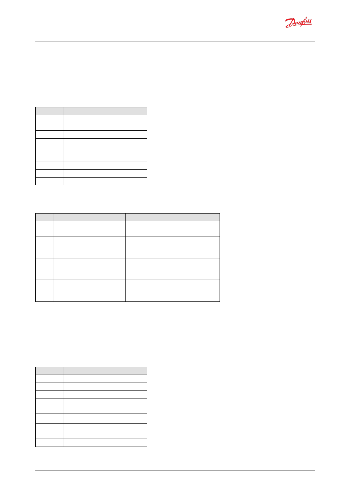
9.5.2.2 Service 1 status
The service 1 status message contains information re lating to the current operating conditions of service 1 of
the DDP096 software and pump.
9.5.2.2.1 Message information
Name Service 1 status
Priority 3
Data page 0
PDU format 0xFF
PDU specific 0xDD (message ID MSB)
Source address DPC12 node ID (zz)
Full message ID 0x0CFFDDzz
DLC (length) 8
Direction Transmitted by DPC12
Occurrence Repeated every 10 ms
9.5.2.2.2 Message data
Byte no. Enco ding Value/r ange Description
0 0x80 Message ID (LSB)
1 All bits set to 1 Reserved
2...3 SAEpc11 0...100%: Valid
0xFExx: Error indicator
0xFFxx: Not used/not
requested
Actual service displacement, see ACTL_DISP_S1 parameter
4...5 SAEpr08 0...60000 kPa (600 bar): Valid
0xFExx: Error indicator
0xFFxx: Not used/not
requested
Actual service pressure, see ACTL_PRESS_S1 parameter
6...7 SAEpr08 0...100000 kPa (1000 bar): Valid
0xFExx: Error indicator
0xFFxx: Not used/not
requested
Actual service LS pressure, see ACTL_LS_PRESS_S1
parameter
9.5.2.3 Service 2 status
The service 2 status message contains information re lating to the current operating conditions of service 2 of
the DDP096 software and pump.
9.5.2.3.1 Message information
Name Service 2 status
Priority 3
Data page 0
PDU format 0xFF
PDU specific 0xDD (message ID MSB)
Source address DPC12 node ID (zz)
Full message ID 0x0CFFDDzz
DLC (length) 8
Direction Transmitted by DPC12
Occurrence Repeated every 10 ms
Software Manual
Digital Displacement® Pump Software Version 2.7.1
46 | © Danfoss | February 2022 BC404560709540en-000102
Page 47
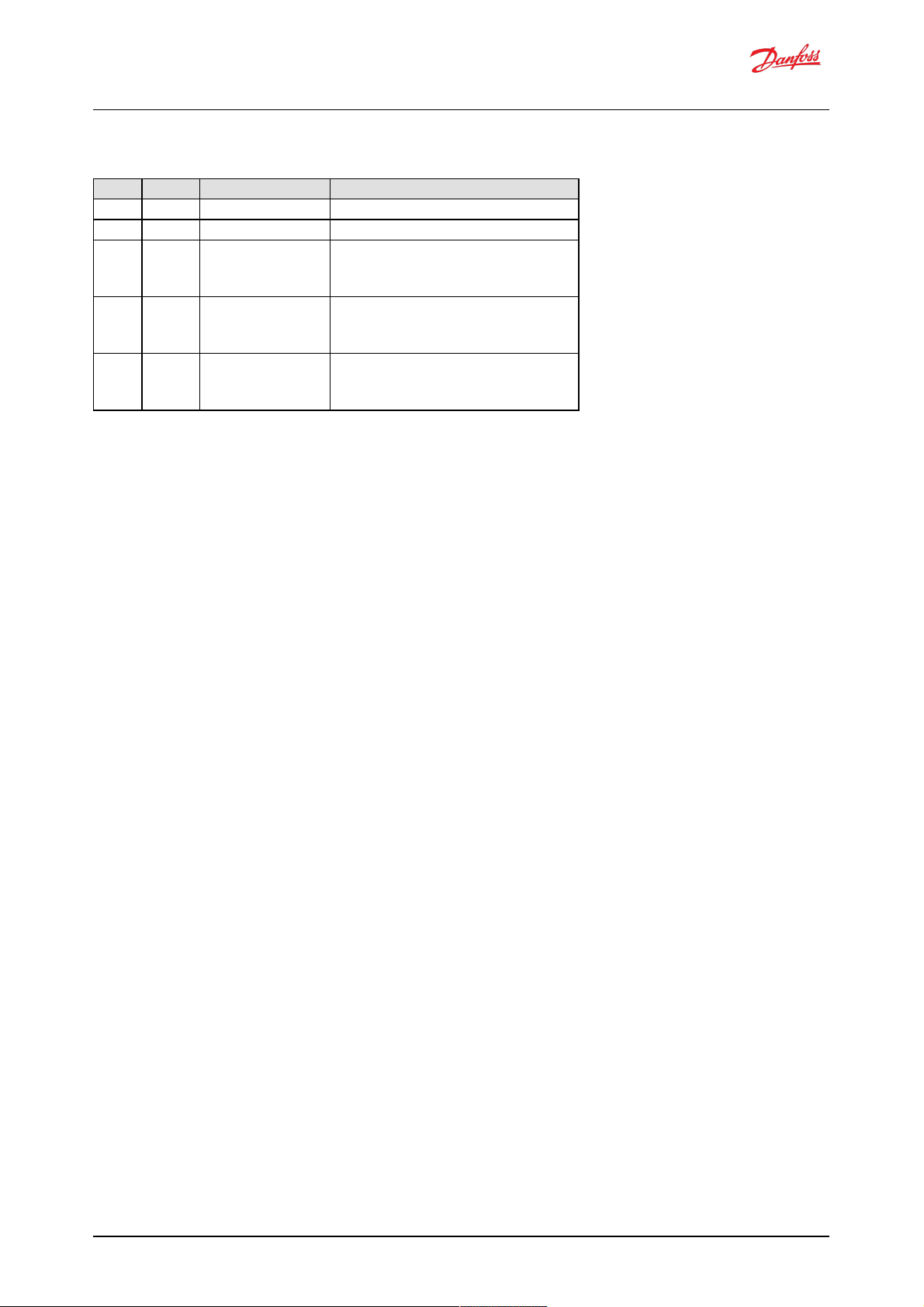
9.5.2.3.2 Message data
Byte no. Enco ding Value/r ange Description
0 0x81 Message ID (LSB)
1 All bits set to 1 Reserved
2...3 SAEpc11 0...100%: Valid
0xFExx: Error indicator
0xFFxx: Not used/not
requested
Actual service displacement, see ACTL_DISP_S2 parameter
4...5 SAEpr08 0...60000 kPa (600 bar): Valid
0xFExx: Error indicator
0xFFxx: Not used/not
requested
Actual service pressure, see ACTL_PRESS_S2 parameter
6...7 SAEpr08 0...100000 kPa (1000 bar): Valid
0xFExx: Error indicator
0xFFxx: Not used/not
requested
Actual service LS pressure, see ACTL_LS_PRESS_S2
parameter
Software Manual
Digital Displacement® Pump Software Version 2.7.1
47 | © Danfoss | February 2022 BC404560709540en-000102
Page 48

10 Updating software on the controller
The softw are on the DPC12 controller can be updated in the field by using the PLUS+1® Se rvice Tool. Ple ase
refe r to the PLUS+1® Service Tool manual for instructions on this process.
Ple ase read the relevant release notes before upd ating the software. Systems should be recommissioned
after updating to ensure the DDP096 pump functions as desired.
The parameters on the DPC12 controller should be backed up before upgrading the softw are. If the software
is upgraded to a version w ith new parameters the non-volatile memory format may be incompatible and the
parame ters reset to the ir default value. Please check all parameters after the update has been completed.
Warning
Parameters may be reset to default during a softw are upd ate.
Contact your Danfoss representative for assistance when updating if required.
Software Manual
Digital Displacement® Pump Software Version 2.7.1
48 | © Danfoss | February 2022 BC404560709540en-000102
Page 49

11 References
Dig ital Disp lacement® Pump Gen 1 DDP096 and DPC12 Technical Information
- https://www.danfoss.com/en/products/d ps/pumps/digital-d isplacement-pump s/dig ital-d isplacement-
single-and -multiple-outlet-pumps/#tab-documents
PLUS+1® Service Tool d ownload
- https://www.danfoss.com/en/products/d ps/software/softw are-and-tools/plus1-software/#tab-d ownloads
SAE J1939 Digital Annex
- https://www.sae .org /standard s/content/j1939da_202103/
Software Manual
Digital Displacement® Pump Software Version 2.7.1
49 | © Danfoss | February 2022 BC404560709540en-000102
Page 50

50 | © Danfoss | February 2022 BC404560709540en-000102
 Loading...