

Page 1
User Manual
PLUS+1® Compliant
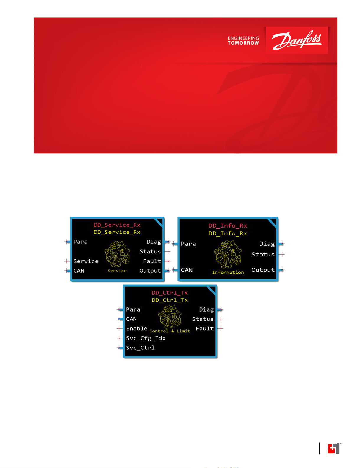
Digital Displacement (DD) Function
Blocks
www.danfoss.com
Page 2
User Manual
Digital Displacement (DD) Function Blocks
Revision history Table of revisions
Date Changed Rev
September 2021 First edition 0101
2 | © Danfoss | September 2021 BC384074844183en-000101
Page 3

User Manual
Digital Displacement (DD) Function Blocks
Contents
Introduction
DD Application Configuration
Configure the DD Information Function Block......................................................................................................................5
Configure the DD Service Function Block............................................................................................................................... 5
Configure DD Service Rx Service Screens...........................................................................................................................6
Configure the DD Control and Limit Function Block...........................................................................................................7
Configure DD Services...............................................................................................................................................................8
Using Namespaces...........................................................................................................................................................................9
Change Namespace Value.....................................................................................................................................................10
Setup Configuration Parameter Inputs..................................................................................................................................10
DD Information Function Block
DD Information Function Block Inputs.................................................................................................................................. 11
DD Information Function Block Outputs...............................................................................................................................12
DD Information Service Screen.................................................................................................................................................13
DD Service Function Block
DD Service Function Block Inputs............................................................................................................................................15
DD Service Function Block Outputs........................................................................................................................................16
DD Service Rx Service Screen.....................................................................................................................................................17
DD Control and Limit Function Block
DD Control and Limit Function Block Inputs....................................................................................................................... 19
DD Control and Limit Function Block Parameters........................................................................................................20
DD Control and Limit Function Block Outputs....................................................................................................................21
Service Configuration Items.......................................................................................................................................................22
DD Control and Limit Service Screens....................................................................................................................................23
©
Danfoss | September 2021 BC384074844183en-000101 | 3
Page 4
User Manual
Digital Displacement (DD) Function Blocks
Introduction
The Digital Displacement Function Blocks provide configuration parameters for the Digital Displacement
Pump (DDP) as well as gather and report data from the DDP. This document provides instructions for
configuring the DDPDD Function Blocks and descriptions of the parameters and signals used in the
function blocks.
For instructions on configuring a basic application for the DDP, see DD Application Configuration on page
5.
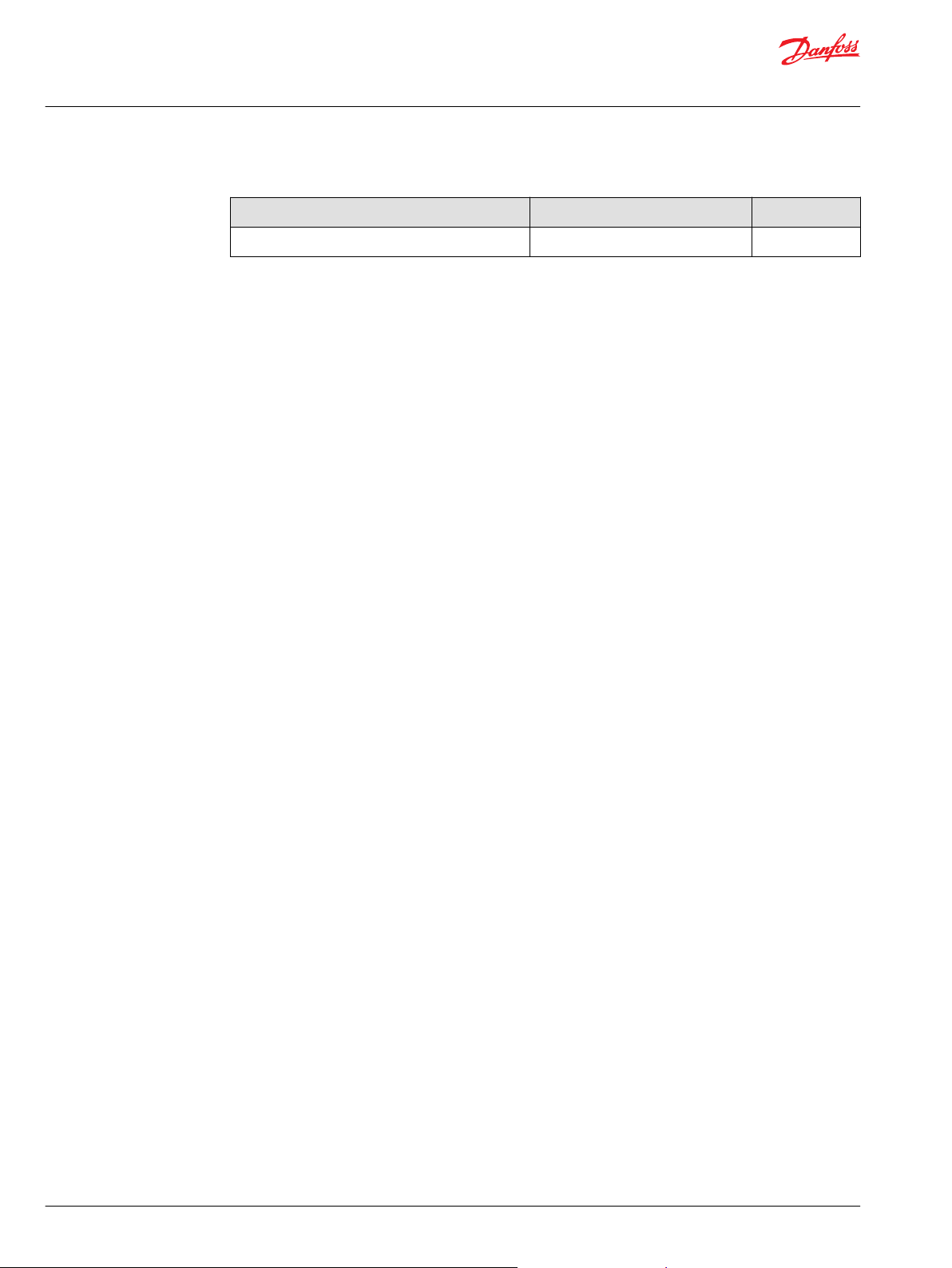
DD Information Function Block:
•
The DD Information Function Block receives data from the DDP. For more information on DD
Information Function Block parameters and settings, see DD Information Function Block on page 11.
DD Service Function Block:
•
The DD Service Function Block receives data from the selected DD service. For more information on
DD Service Function Blocks parameters and settings, see DD Service Function Block on page 15.
DD Control and Limit Function Block:
•
The DD Control and Limit Function Block configures the DDP and DD services. For more information
on DD Control and Limit Function Block parameters and settings, see DD Control and Limit Function
Block on page 19.
4 | © Danfoss | September 2021 BC384074844183en-000101
Page 5
User Manual
Digital Displacement (DD) Function Blocks
DD Application Configuration
This section provides instructions for configuring the DD Function Blocks. The instructions here describe
the basic process for configuring the function blocks for an application. Your application will require
additional configuration steps to customize the DDP for your purposes.
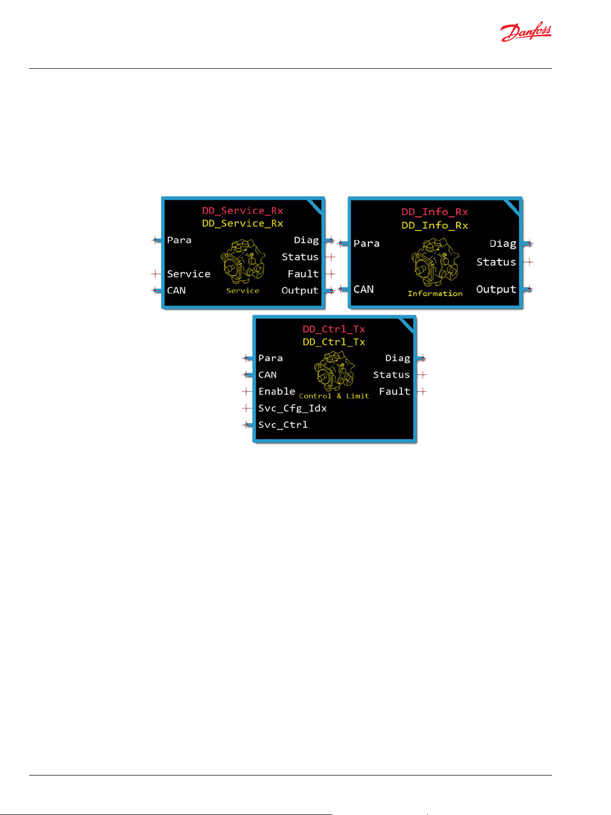
Configure the DD Information Function Block
The DD Information Function Block gathers information from the DDP. Follow these steps to configure
the DD Information Function Block. This task describes a basic configuration process. Your application
might require additional configuration steps.
1. Add the DD Information Function Block to the application.
2. Route the CAN bus on the function block to the CAN input BUS that contains CAN communication
from the DDP.
3. Enter the DDP CAN address in the value for DD_Addr if the CAN address of the DDP is different from
the default.
4. Save the project.
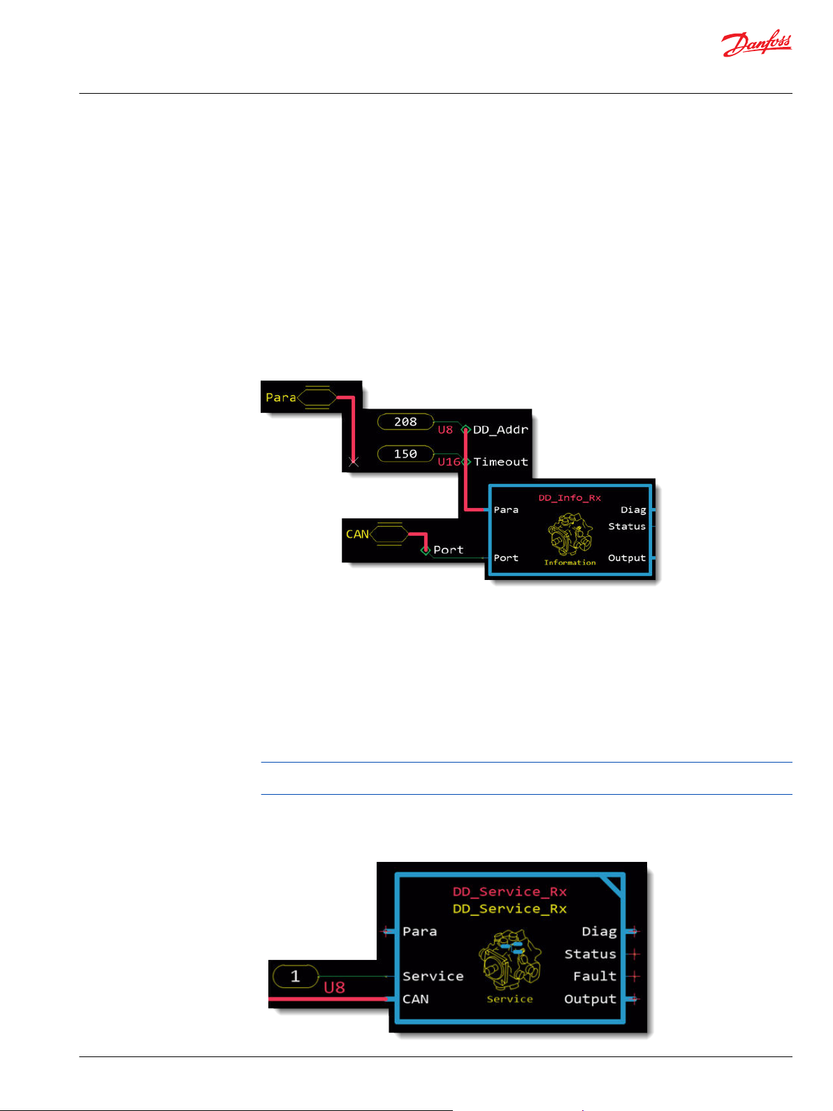
Configure the DD Service Function Block
The DD Service Function Block gathers and reports information from a DD service. Follow these steps to
configure the function block. This task describes a basic configuration process. Your application might
require additional configuration steps.
1. Add a DD Service Function Block to your application for each DD service you intend to use.
2. Modify the namespace of each function block to a unique name that indicates which DD service it
monitors.
Identical namespace values will result in errors when compiling the application. For more information
on changing the namespace, see Using Namespaces on page 9.
3. Route the CAN input BUS on the function block to the CAN input BUS that contains CAN
communication from the DDP.
4. Set a DD service number on the Service input of the function block.
©
Danfoss | September 2021 BC384074844183en-000101 | 5
Page 6
User Manual
Digital Displacement (DD) Function Blocks
DD Application Configuration
a) Add a 3 Character Typed Constant component and route it to the Service input.
b) Set the value to the number of the service configured in the DD Control and Limit Function Block.
c) Set the Type to U8.
5. Save the project.
6. Configure the service screens. For instructions, refer to Configure DD Service Rx Service Screens on page
6.
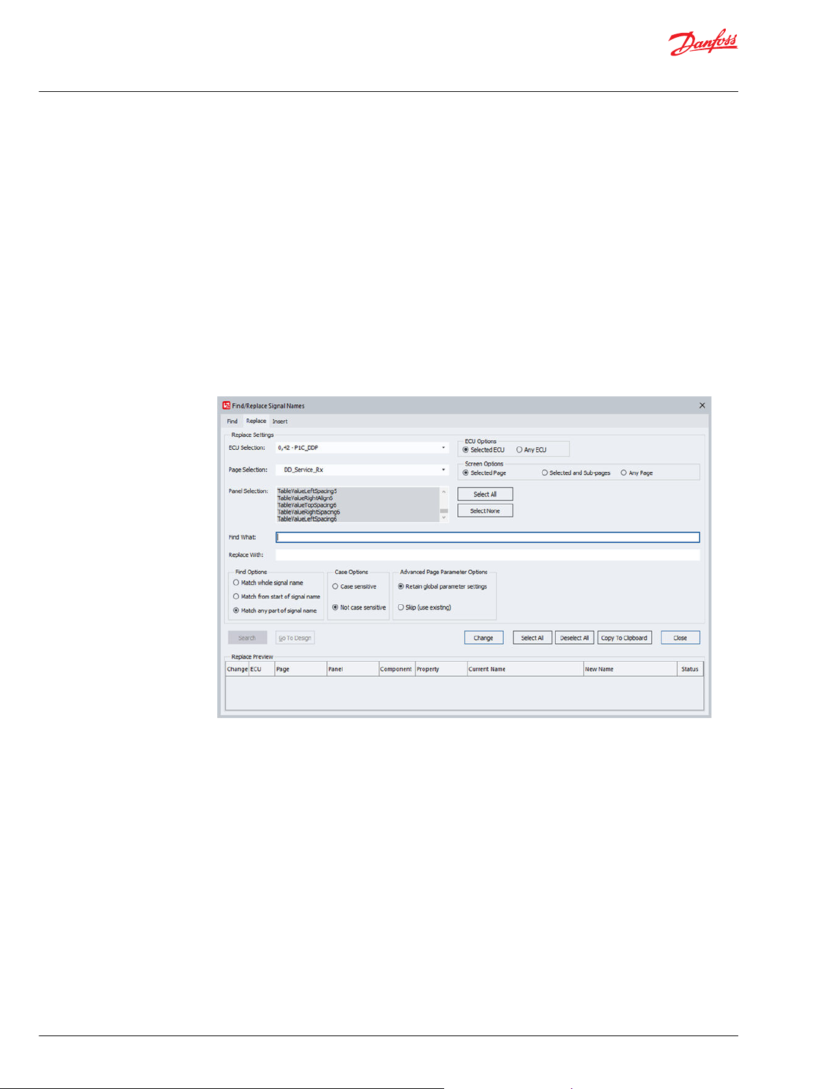
Configure DD Service Rx Service Screens
After changing the namespace for DD Service Function Blocks, you must configure the DD Service RX
Service Screens to communicate with the function blocks using the new namespace. This is not necessary
if the DDP uses only one service and the DD Service Function Block uses the default namespace.
1. Open the PLUS+1 Service Tool.
2. Add a DD Service Rx Service Screen for each DD Service Function Block.
3. Select Edit > Find/Replace Signal Names.
4. Select the Replace tab.
5. From the ECU Selection list, select the ECU for the function block.
6. From the Page Selection list, select the service screen to modify.
7. Next to the Panel Selection area, click Select All.
8. In the Find What field, enter the former function block namespace value .
9. In the Replace With field, enter the new function block namespace value.
10. Select Match any part of signal name.
11. Click Search. The PLUS+1 Service Tool finds all instances of the searched text.
12. Click Change. The PLUS+1 Service Tool replaces the former namespace with the new namespace.
13. Save the system.
14. Repeat these steps for any additional function blocks that have changed namespaces.
6 | © Danfoss | September 2021 BC384074844183en-000101
Page 7
User Manual
Digital Displacement (DD) Function Blocks
DD Application Configuration
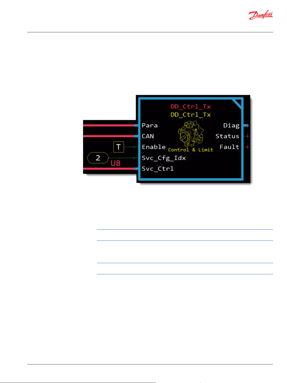
Configure the DD Control and Limit Function Block
The DD Control and Limit Function Block configures the operation of the DDP. Follow these steps to
configure the function block. This task describes a basic configuration process. Your application might
require additional configuration steps.
For more information on DD Control and Limit Function Block parameters and settings, see DD Control
and Limit Function Block on page 19.
1. Add the DD Control and Limit Function Block to the application.
2. Route the CAN input on the function block to the CAN input BUS that carries CAN communication
from the DDP.
3. Configure the Src_Addr parameter with the J1939 address of the controller.
Add a 3-Character Typed Constant component and set the address of the local controller.
•
Route it to an external input to allow an external control.
•
To prevent conflicts with other addresses, use the Address output of the AddrClaim_Tx_Rx
function block in the J1939 Function Block Library.
4. Enable the function block with the Enable input.
Add a True or False component.
•
Route it to an external input to enable or disable the function block from an external control.
•
To prevent conflicts with other addresses, use the Claimed output of the AddrClaim_Tx_Rx
function block in the J1939 Function Block Library.
5. Configure the Svc_Cfg_Idx (service configuration index) input.
Route it to an external input to allow an external input to set the service configuration index.
•
Add a 3-Character Typed Constant component and set service configuration index.
•
6. Route the Svc_Ctrl (service control) BUS to the input BUS.
7. Save the project.
8. Configure the services. For instructions, see Configure DD Services on page 8.
©
Danfoss | September 2021 BC384074844183en-000101 | 7
Page 8
User Manual
Digital Displacement (DD) Function Blocks
DD Application Configuration
Configure DD Services
The DDP can provide flow to two different hydraulic circuits. Services in the DD Control and Limit
Function Block control the functionality of the DDP for each hydraulic circuit. Follow these steps to
configure DD services.
•
Danfoss supports specific combinations of service configuration parameters. For more information on
the supported use cases, see the Digital Displacement Pump Software Manual.
•
For more information on DD service configuration items, see Service Configuration Items on page 22.
1. In the DD Control and Limit Function Block, break the link between the service pages you want to
modify.
a) Select Edit > Break Reference Link to Page.
b) Click on the service page. A confirmation dialog box opens.
c) Click Yes.
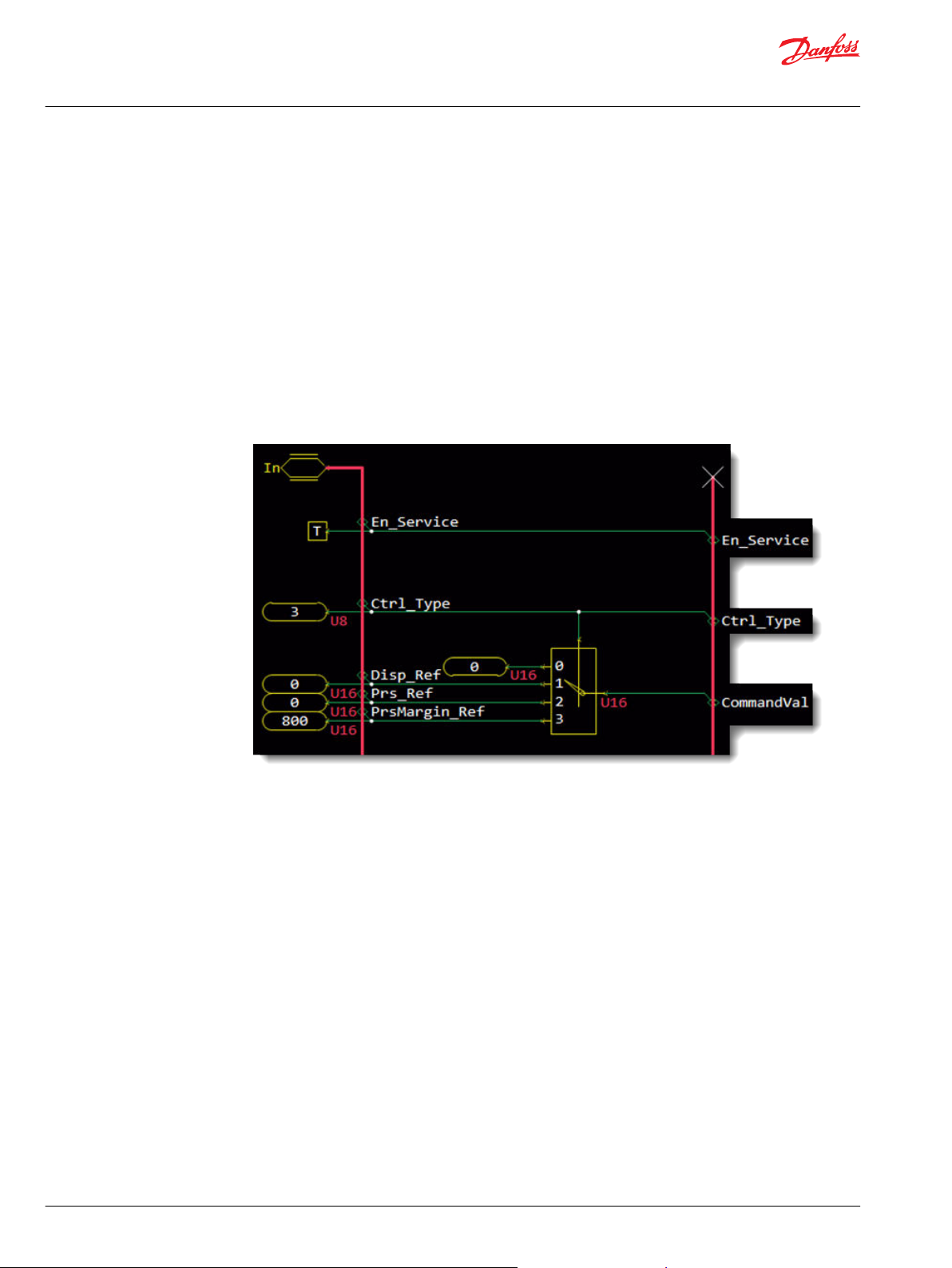
2. Enter a service page.
3. Enable the service.
Query the False constant to the En_Service signal then change the modifier to True.
•
Or, delete the False constant component to En_Service to allow an external signal to enable and
•
disable the service.
4. Set the Ctrl_Type (control type) for the service.
a) Query the typed constant component connected to the Ctrl_Type.
b) Enter a value that corresponds to the control type.
5. Configure the reference value for the selected control type.
a) Query a typed constant component connected to Disp_Ref, Prs_Ref, or PrsMargin_Ref.
b) Enter a reference value for the control type.
8 | © Danfoss | September 2021 BC384074844183en-000101
Page 9

User Manual
Digital Displacement (DD) Function Blocks
DD Application Configuration
6. Follow these steps to set a torque limit on the service.
Using Namespaces
a) Set the True/False constant component connected to En_Torq_Limit to True.
b) Query the typed constant component connected to Torq_Limit and enter a torque limit value.
7. Follow these steps to set a flow limit on the service.
a) Set the True/False constant component connected to En_Flow_Limit to True.
b) Query the typed constant component connected to Flow_Limit and enter a flow limit value.
8. Follow these steps to set a power limit on the service.
a) Set the True/False constant component connected to En_Pwr_Limit to True.
b) Query the typed constant component connected to Pwr_Limit and enter a power limit value.
9. Save the project.
Namespaces can help you successfully compile an application that uses the same function block more
than once.
Change each function block's namespace by setting its Namespace value to something unique. If you do
not change the Namespace value, you cannot compile the application.
The Namespace value adds a unique prefix to each component name.
Also, if you want to use these function blocks' companion Service Tool screens, you must include the
function block's advanced checkpoint with namespace in the application's compiled .lhx file. Use the
function block's Checkpoints page to include the checkpoint.
©
Danfoss | September 2021 BC384074844183en-000101 | 9
Page 10

User Manual
Digital Displacement (DD) Function Blocks
DD Application Configuration
Change Namespace Value
To successfully compile your application, change the namespace value for function blocks that are used
more than once in an application.
1. In the PLUS+1® GUIDE menu bar, click the Query/Change button.
2. Click on the function block whose namespace you want to set to a unique value.
The Edit Page window opens.
3. In the Edit Page window, enter a meaningful Namespace value.
Namespace values are case-sensitive.
•
To save controller memory, use a short namespace value.
•
4. Press Enter.
5. Repeat these steps to enter unique namespace values for other identical function blocks.
Setup Configuration Parameter Inputs
Use the parameter (Para) input to apply a common set of configuration parameters to multiple function
blocks. Follow these steps to setup configuration parameter inputs for the application.
1. Create a Parameters page to hold the configuration parameters the function blocks will share.
2. Connect the Parameters page to the Para input of the DD Function Block.
3. Add the configuration parameters and their values to the Parameters page.
a) Copy the configuration parameters from the function block.
b) Paste the configuration parameters into the Parameters page.
c) Route the parameters to the Para output of the Parameters page.
d) Modify the configuration parameters as needed.
4. In the function block, route each configuration parameter to the Para input bus and connect it to the
corresponding input signal.
To avoid compiler errors, ensure that the Namespace value for each function block is unique.
10 | © Danfoss | September 2021 BC384074844183en-000101
Page 11

User Manual
Digital Displacement (DD) Function Blocks
DD Information Function Block
The DD Information Function Block receives data from the DDP. This chapter provides information on
inputs, outputs, and parameters used to configure the function block for your application.
DD Information Function Block Inputs
The table below describes the inputs to the DD Information Function Block.
Item Type Range Description [Unit]
Para BUS ––
CAN BUS ––
DD_Addr U8 0–238
Timeout U16 10–1000
Port Port ––
Holds configuration values for the function block. Route
signals from the application to control the configuration
values from the application.
For information on configuring parameters for external
control, refer to Setup Configuration Parameter Inputs on
page 10.
The CAN address of the DD controller. The default value
is 208.
The time in milliseconds between messages after which a
fault is triggered. The default value is 150.
[ms]
BUS containing the port sub-signal and CAN messages.
Sets the physical CAN port on the DDP that receives data.
This variable can be found in the CAN sub-BUS if using
the Main Template.
©
Danfoss | September 2021 BC384074844183en-000101 | 11
Page 12

User Manual
Digital Displacement (DD) Function Blocks
DD Information Function Block
DD Information Function Block Outputs
The table below describes the output signals from the DD Information Function Block.
Item Type Description
Diag BUS
Status U16 Reports the status of the function block.
Output BUS Contains all of the output values for the function block.
The following table includes descriptions for sub-signals contained in the Output bus.
Output Sub-Signals
Item Type Range Description [Unit]
Act_Shaft_Spd S16 -3500–3500
Act_Pump_Temp S16 -40–150
Device_State U8 0–13
Device_Mode U8 0–13
Sig_Status BUS ––
Act_Shaft_Spd_NA
Act_Pump_Temp_NA
Device_State_NA
Device_Mode_NA
Sig_Fault BUS T/F
Act_Shaft_Spd_Flt
Act_Pump_Temp_Flt
Device_State_Flt
Device_Mode_Flt
Updated BOOL T/F
Provides diagnostic data for troubleshooting as well as all parameters and
output signals.
0x0000: Status OK.
0x8008: At least one parameter is out of range.
This output uses a bitwise-reporting scheme where multiple items can be
reported at a time.
BOOL T/F
BOOL T/F
The speed of the shaft in the DDP. Positive values
indicate clockwise rotation of the shaft. Negative values
indicate counter-clockwise rotation of the shaft.
[rpm]
The temperature of the DDP.
[°C]
The current state of the DD controller.
0: Initializing
1: Disabled
2: Active
3: Error
4: Error Hold
5–13: Reserved
The current mode of the DD controller. Options include
Normal, Limp, and Commissioning.
0: Normal
1: Limp
2: Commissioning
3–13: Reserved
Bus containing signals that indicate the availability of the
output signals from the DDP.
Indicates the availability of the specified output signal.
T: The signal is unavailable
F: The signal is available
Bus containing signals that indicate the fault status of the
output signals.
Indicates the fault status of the specified output signal.
T: The signal has a fault
F: The signal is OK and does not have a fault
Indicates that the function block received new data in the
current cycle.
T: Received new data
F: Did not receive new data
12 | © Danfoss | September 2021 BC384074844183en-000101
Page 13

User Manual
Digital Displacement (DD) Function Blocks
DD Information Function Block
Output Sub-Signals (continued)
Item Type Range Description [Unit]
NoMsgReceived BOOL T/F
MsgTimedOut BOOL T/F
DD Information Service Screen
The DD Information service screen presents information on the Digital Displacement Pump from the DD
Information Function Block. The following table describes the data provided by the DD Information
service screen.
Indicates that a message has not been received from the
device since powering it on.
T: The function block has not received a message
F: The function block received a message
Indicates that the time between messages from the
device has exceeded the Timeout value. If the timeout
has been exceeded, the function block retains the last
received values for the output signals.
T: The message timed out
F: No error
Item Description
Parameter
DD_Addr
Timeout
Outputs
Status
No Messages Received
©
Danfoss | September 2021 BC384074844183en-000101 | 13
The CAN address of the DD controller. The default value is 208.
The time in milliseconds between messages after which a fault is triggered. The default
value is 150.
Reports the status of the function block.
Indicates that a message has not been received from the device since powering it on.
Page 14
User Manual
Digital Displacement (DD) Function Blocks
DD Information Function Block
Item Description
Reception Timeout
Actual Shaft Speed
Actual Pump
Temperature
Device State
Device Mode
Output Signal Availability and Fault Statuses
Not Available
Fault
Indicates that the time between messages from the device has exceeded the Timeout
value. If the timeout has been exceeded, the function block retains the last received
values for the output signals.
The speed of the shaft in the DDP. Positive values indicate clockwise rotation of the
shaft. Negative values indicate counter-clockwise rotation of the shaft.
The temperature of the DDP.
The current state of the DD controller.
The current mode of the DD controller. Options include Normal, Limp, and
Commissioning.
Indicates the availability of the specified output signal.
Indicates the fault status of the specified output signal.
14 | © Danfoss | September 2021 BC384074844183en-000101
Page 15

User Manual
Digital Displacement (DD) Function Blocks
DD Service Function Block
The DD Service Function Block receives data from the selected DD service. This chapter provides
information on input, output, and parameter signals.
DD Service Function Block Inputs
The table below describes input signals for the DD Service Function Block.
Item Type Range Description [Unit]
Para BUS ––
CAN BUS ––
Service U8 1–8
DD_Addr U8 0–238
Timeout U16 10–1000
Port Port ––
Holds configuration values DD_Addr and Timeout.
For information on configuring parameters for external
control, refer to Setup Configuration Parameter Inputs on
page 10.
The CAN address of the DD controller. The default value
is 208.
The time in milliseconds between messages after which a
fault is triggered. The default value is 150.
[ms]
BUS containing the port sub-signal and CAN messages.
Sets which physical CAN port of the hardware to receive
data from. This variable can be found in the CAN sub-BUS
if using the Main Template.
Sets the DD service from which the function block
receives data. A DD Service Function Block can receive
data from only one DD service. To receive data from
multiple DD services, add a DD Service Function Block to
the application for each DD service.
©
Danfoss | September 2021 BC384074844183en-000101 | 15
Page 16

User Manual
Digital Displacement (DD) Function Blocks
DD Service Function Block
DD Service Function Block Outputs
The following table describes output signals for the DD Service Function Block.
Item Type Description [Unit]
Diag BUS
Status U16
Fault U16
Output BUS
Provides diagnostic data for troubleshooting as well as all
parameters and output signals.
Reports the status of the function block.
0x0000: Status OK.
0x8008: At least one parameter is out of range.
This output uses a bitwise-reporting scheme where
multiple items can be reported at a time.
Reports fault statuses for the function block.
0x0000: No fault
0x8001: Input value is too low
0x8002: Input value is too high
This output uses a bitwise-reporting scheme where
multiple items can be reported at a time.
Contains all of the output signals for the function block.
For more information on the signals contained within
Output, see Output Sub-Signals on page 16.
The following table includes descriptions for sub-signals contained in the Output bus.
Output Sub-Signals
Item Type Range Description [Unit]
Displacement U16
Prs U16
Load_Prs U32
Sig_Status BUS ––
Displacement_NA
Prs_NA
Load_Prs_NA
Sig_Fault BUS T/F
Displacement_Flt
Prs_Flt
Load_Prs_Flt
Updated BOOL T/F
BOOL T/F
BOOL T/F
0–10000 The displacement reading from the DDP.
[0.01%]
0–60000 The pressure reading from the DDP.
Displayed at a resolution of 2 kPa.
[0.01 bar/1 kPa]
0–100000 The load pressure reading from the DDP.
Displayed at a resolution of 2 kPa.
[0.01 bar/1 kPa]
Bus containing signals that indicate the
availability of the output signals from the
DDP.
Indicates the availability of the specified
output signal.
T: The signal is unavailable
F: The signal is available
Bus containing signals that indicate the
fault status of the output signals.
Indicates the fault status of the specified
output signal.
T: The signal has a fault
F: The signal is OK and does not have a
fault
Indicates that the function block received
new data in the current cycle.
T: Received new data
F: Did not receive new data
16 | © Danfoss | September 2021 BC384074844183en-000101
Page 17

User Manual
Digital Displacement (DD) Function Blocks
DD Service Function Block
Output Sub-Signals (continued)
Item Type Range Description [Unit]
NoMsgReceived BOOL T/F
MsgTimedOut BOOL T/F
DD Service Rx Service Screen
The DD Service Rx service screen displays information on the Digital Displacement PumpDD Service
Function Block. The following table describes the data provided by the DD Service Rx service screen.
Indicates that a message has not been
received from the device since powering it
on.
T: The function block has not received a
message
F: The function block received a message
Indicates that the time between messages
from the device has exceeded the
Timeout value. If the timeout has been
exceeded, the function block retains the
last received values for the output signals.
T: The message timed out
F: No error
Item Description
Input
Service #
Parameter
DD Address
Timeout
Outputs
©
Danfoss | September 2021 BC384074844183en-000101 | 17
The number of the service set on the function block.
The CAN address of the DD controller. The default value is 208.
The time in milliseconds between messages after which a fault is triggered. The default
value is 150.
Page 18

User Manual
Digital Displacement (DD) Function Blocks
DD Service Function Block
Item Description
Displacement
Pressure
Load Pressure
NoMsgReceived
MsgTimeOut
Status
Fault
Output Signal Availability and Fault Statuses
Not Available
Fault
The displacement reading from the DDP.
The pressure reading from the DDP. Displayed at a resolution of 2 kPa.
The load pressure reading from the DDP. Displayed at a resolution of 2 kPa.
Indicates that a message has not been received from the device since powering it on.
Indicates that the time between messages from the device has exceeded the Timeout
value. If the timeout has been exceeded, the function block retains the last received
values for the output signals.
Reports the status of the function block.
Reports fault statuses for the function block.
Indicates the availability of the specified output signal.
Indicates the fault status of the specified output signal.
18 | © Danfoss | September 2021 BC384074844183en-000101
Page 19

User Manual
Digital Displacement (DD) Function Blocks
DD Control and Limit Function Block
The DD Control and Limit Function Block configures the DDP and DD services. This chapter provides
information used to configure the function block.
DD Control and Limit Function Block Inputs
The following table describes input signals for the DD Control and Limit Function Block.
Item Type Range Description [Unit]
Para BUS ––
Loop_Tm U16 0–65535
CAN BUS ––
Port Port ––
Enable BOOL T/F
Svc_Cfg_Idx U8 0–15
Holds configuration values for the function block. Route
signals from the application to control the configuration
values from the application.
For more information, see DD Control and Limit Function
Block Parameters on page 20.
Sets the processing time of one program loop.
[ms]
BUS containing the port sub-signal and CAN messages.
Sets which physical CAN port of the hardware to receive
data from. This variable can be found in the CAN sub-BUS
if using the Main Template.
Enables and disables the function block.
T: Enables the function block
F: Disables the function block
Sets the Service Configuration Index or the index for
cylinder combination for service outlet. This sets the
combination of pumplets assigned to DD services.
0: Service 1 uses pumplet 1+3. Service 2 uses pumplets
•
2 and 4.
1: Service 1 uses pumplet 1+3. Service 2 uses pumplet
•
4.
2: Service 1 uses pumplet 1+3 and 2. Service 2 uses
•
pumplet 4.
3–15: Reserved
•
©
Danfoss | September 2021 BC384074844183en-000101 | 19
Page 20

User Manual
Digital Displacement (DD) Function Blocks
DD Control and Limit Function Block
Item Type Range Description [Unit]
Svc_Ctrl BUS ––
Chkpt BOOL T/F
DD Control and Limit Function Block Parameters
The following table describes parameters for the DD Control and Limit Function Block.
For information on configuring parameters for external control, refer to Setup Configuration Parameter
Inputs on page 10.
Contains controls for DD services. Default signals are
present but, by default, will not send commands. Enter
the page corresponding to the service to customize it for
your application.
For instructions, see Configure DD Services on page 8.
Enables advanced checkpoints using Namespace for
each diagnostic signal.
T: Enables advanced checkpoints.
F: Disables advanced checkpoints.
Item Type Range Description
Priority U8
TxRate_CtrlMsgs U8
0-7 Sets the priority of CAN messages from the DD controller
to the DDP.
0 is the highest priority and 7 is the lowest priority. 3 is
the default priority.
0-5 Sets the rate at which the DD controller sends control
messages to the DDP.
0: 10 ms
1: 20 ms
2: 50 ms
3: 100 ms
4: 200 ms
5: 300 ms
If this rate is less than the twice Loop_Tm, the DD
Control and Limit Function Block increases the rate to
twice Loop_Tm.
20 | © Danfoss | September 2021 BC384074844183en-000101
Page 21

User Manual
Digital Displacement (DD) Function Blocks
DD Control and Limit Function Block
Item Type Range Description
TxRate_CfgMsgs U8
DD_Addr U8
Src_Addr U8
En_SetupCmdMsg BOOL
Send_LimpCmdMsg BOOL
En_LimpMode BOOL
NotAvailable_UseZero BOOL T/F
0-5 Sets the rate at which the DD controller sends
configuration messages to the DDP.
0: 10 ms
1: 20 ms
2: 50 ms
3: 100 ms
4: 200 ms
5: 300 ms
If this rate is less than the twice Loop_Tm, the DD
Control and Limit Function Block increases the rate to
twice Loop_Tm.
0-238 The CAN address of the DD controller. The default value
is 208.
0-253 The CAN address of the device sending the
communication.
T/F Enables or disables setup command messages.
T: Enables message transmission
F: Disables message transmission
T/F Enables or disables transmission of Limp Mode
commands from the DD controller.
T: Enables command transmission
F: Disables command transmission
T/F Enables or disables Limp Mode. Used in the event of a
mechanical error, Limp Mode limits the functionality of
the DDP to prevent further damage to the DDP.
T: Enables Limp Mode
F: Disables Limp Mode
Sets how the DDP sends signal values when the signals
are unavailable.
T: Sets unavailable signals to send a value that is
functionally 0. Scaled and offset values also result in 0
values.
F: Sets unavailable signal values to 1.
DD Control and Limit Function Block Outputs
The table below describes the outputs signals for the DD Control and Limit Function Block.
Item Type Description
Diag BUS
Status U16 Reports the status of the function block.
Fault U16
©
Danfoss | September 2021 BC384074844183en-000101 | 21
Provides diagnostic data for troubleshooting as well as all parameters and
output signals.
0x0000: Status OK.
0x8008: At least one parameter is out of range.
This output uses a bitwise-reporting scheme where multiple items can be
reported at a time.
Reports fault statuses for the function block.
0x0000: No fault
0x8002: Input value is too high, transmission is interrupted
This output uses a bitwise-reporting scheme where multiple items can be
reported at a time.
Page 22

User Manual
Digital Displacement (DD) Function Blocks
DD Control and Limit Function Block
Service Configuration Items
The following table describes the items in the Service pages used to configure a DPP service.
Item Type Range Description [Unit]
En_Service BOOL T/F
Ctrl_Type U8 0-3
CommandVal U16 --
Disp_Ref U16 0-10000
Prs_Ref U16 0-42000
PrsMargin_Ref U16 0-10000
En_Torq_Limit BOOL T/F
Torq_Limit U16 0-15000
En_Flow_Limit BOOL T/F
Flow_Limit U16 0-30000
En_Pwr_Limit BOOL T/F
Pwr_Limit U16 0-50000
Enables or disables the DD service.
T: Enables the DD service
F: Disables the DD service
Sets the control type on the DD service. The control type
controls how pump operates. The following list describes
the control types.
0: No active control
1: Displacement Reference Control: The DDP maintains
a set displacement percentage during operation.
2: Pressure Reference Control: The DDP maintains a set
pressure level at its output during operation.
3: Pressure Margin Reference Control: The DDP
maintains a pressure at its output that is a set margin
greater than the pressure at the input.
Toggles between the control reference values for the
different control types.
Displacement reference for Displacement Control
Reference.
[0.01%]
Pressure reference for Pressure Reference Control.
[0.01 bar / 1 kPa]
Resolution: 2 kPa
The pressure margin reference for Pressure Margin
Reference Control.
[0.01 bar / 1 kPa]
Resolution: 2 kPa
Enables a torque limit for the DD service. After enabling,
set the torque limit using Torq_Limit.
T: Enables the torque limit
F: Disables the torque limit
Sets the torque limit after enabling En_Torq_Limit.
[0.1 Nm]
Resolution: 0.2 Nm
Enables a flow limit for the DD service. After enabling, set
the flow limit using Flow_Limit.
T: Enables the flow limit
F: Disables the flow limit
Sets the flow limit after enabling En_Flow_Limit.
[0.01 liters/min]
Resolution: 0.05 liters/min
Enables a power limit for the DD service. After enabling,
set the power limit using Pwr_Limit.
T: Enables the power limit
F: Disables the power limit
Sets the power limit after enabling En_Pwr_Limit.
[0.01 kW]
Resolution: 0.05 kW
22 | © Danfoss | September 2021 BC384074844183en-000101
Page 23

User Manual
Digital Displacement (DD) Function Blocks
DD Control and Limit Function Block
DD Control and Limit Service Screens
DD Control and Limit Function Block service screens display information provided by the function block.
DD Control Tx
The following table describes data displayed in the DD Control Tx service screen.
Item Description
Inputs
Enable Indicates that the function block is disabled or enabled.
Service Config Index
Service 1
Enable Service
Ctrl Type
Command
Enable Torque Limit
Torque Limit
Enable Flow Limit
Flow Limit
Enable Power Limit
Power Limit
All Services Click to view data from all DD services. After clicking, the PLUS=1 Service Tool loads the
Parameters
Priority
Tx Rate - Ctrl
Indicates the service configuration index that sets the cylinder combination for service
outlet from the DDP.
Indicates that the service is enabled or disabled.
The control type set on the DD service. The control type controls how service operates.
The following list describes the three control types.
Displacement Reference Control: The DDP maintains a set displacement percentage
during operation.
Pressure Reference Control: The DDP maintains a set pressure level at its output
during operation.
Pressure Margin Reference Control: The DDP maintains a pressure at its output that
is a set margin greater than the pressure at the input pressure sensor.
The control reference value type for the different control types.
Indicates that the torque limit is enabled or disabled for the service.
The torque limit value in Newton meters.
Indicates that the flow limit is enabled or disabled for the service.
The flow limit value in liters per minute.
Indicates that the power limit is enabled for the service.
The power limit value in kilowatts.
DD Control Tx - Services service screen.
Sets the priority of CAN messages from the DD controller to the DDP.
0 is the highest priority and 7 is the lowest priority. 3 is the default priority.
Sets the rate at which the DD controller sends control messages to the DDP.
©
Danfoss | September 2021 BC384074844183en-000101 | 23
Page 24

User Manual
Digital Displacement (DD) Function Blocks
DD Control and Limit Function Block
Item Description
Tx Rate - Cfg
DD Address
Src Address
Enable Setup Cmd Msg
Send Limp Cmd Msg
Enable Limp Mode
NotAvailable_UseZero
Outputs
Status
Fault
DD Control Tx - Services
The table below describes the items on the DD Control Tx - Services service screen panels.
Sets the rate at which the DD controller sends configuration messages to the DDP.
The CAN address of the DD controller. The default value is 208.
The CAN address of the device sending the communication.
Enables or disables setup command messages.
Enables or disables transmission of Limp Mode commands from the DD controller.
Enables or disables Limp Mode. Used in the event of a mechanical error, Limp Mode
limits the functionality of the DDP to prevent further damage to the DDP.
Sets how the DDP sends signal values when the signals are unavailable.
T: Sets unavailable signals to send a value that is functionally 0. Scaled and offset values
also result in 0 values.
F: Sets unavailable signal values to 1.
Reports the status of the function block.
Indicates the fault status of the specified output signal.
Item Description
Enable Service
Ctrl Type
Command
Enable Torque Limit
Torque Limit
Enable Flow Limit
Indicates that the service is enabled or disabled.
The control type set on the DD service. The control type controls how service operates.
The following list describes the three control types.
Displacement Reference Control: The DDP maintains a set displacement percentage
during operation.
Pressure Reference Control: The DDP maintains a set pressure level at its output
during operation.
Pressure Margin Reference Control: The DDP maintains a pressure at its output that
is a set margin greater than the pressure at the input pressure sensor.
The control reference value type for the different control types.
Indicates that the torque limit is enabled or disabled for the service.
The torque limit value in Newton meters.
Indicates that the flow limit is enabled or disabled for the service.
24 | © Danfoss | September 2021 BC384074844183en-000101
Page 25
User Manual
Digital Displacement (DD) Function Blocks
DD Control and Limit Function Block
Item Description
Flow Limit
Enable Power Limit
Power Limit
The flow limit value in liters per minute.
Indicates that the power limit is enabled for the service.
The power limit value in kilowatts.
©
Danfoss | September 2021 BC384074844183en-000101 | 25
Page 26

Danfoss
Power Solutions GmbH & Co. OHG
Krokamp 35
D-24539 Neumünster, Germany
Phone: +49 4321 871 0
Danfoss
Power Solutions ApS
Nordborgvej 81
DK-6430 Nordborg, Denmark
Phone: +45 7488 2222
Danfoss
Power Solutions (US) Company
2800 East 13th Street
Ames, IA 50010, USA
Phone: +1 515 239 6000
Danfoss
Power Solutions Trading
(Shanghai) Co., Ltd.
Building #22, No. 1000 Jin Hai Rd
Jin Qiao, Pudong New District
Shanghai, China 201206
Phone: +86 21 2080 6201
Products we offer:
Hydro-Gear
www.hydro-gear.com
Daikin-Sauer-Danfoss
www.daikin-sauer-danfoss.com
Cartridge valves
•
DCV directional control
•
valves
Electric converters
•
Electric machines
•
Electric motors
•
Gear motors
•
Gear pumps
•
Hydraulic integrated
•
circuits (HICs)
Hydrostatic motors
•
Hydrostatic pumps
•
Orbital motors
•
PLUS+1® controllers
•
PLUS+1® displays
•
PLUS+1® joysticks and
•
pedals
PLUS+1® operator
•
interfaces
PLUS+1® sensors
•
PLUS+1® software
•
PLUS+1® software services,
•
support and training
Position controls and
•
sensors
PVG proportional valves
•
Steering components and
•
systems
Telematics
•
Danfoss Power Solutions is a global manufacturer and supplier of high-quality hydraulic and
electric components. We specialize in providing state-of-the-art technology and solutions
that excel in the harsh operating conditions of the mobile off-highway market as well as the
marine sector. Building on our extensive applications expertise, we work closely with you to
ensure exceptional performance for a broad range of applications. We help you and other
customers around the world speed up system development, reduce costs and bring vehicles
and vessels to market faster.
Danfoss Power Solutions – your strongest partner in mobile hydraulics and mobile
electrification.
Go to www.danfoss.com for further product information.
We offer you expert worldwide support for ensuring the best possible solutions for
outstanding performance. And with an extensive network of Global Service Partners, we also
provide you with comprehensive global service for all of our components.
Local address:
Danfoss can accept no responsibility for possible errors in catalogues, brochures and other printed material. Danfoss reserves the right to alter its products without notice. This also applies to products
already on order provided that such alterations can be made without subsequent changes being necessary in specifications already agreed.
All trademarks in this material are property of the respective companies. Danfoss and the Danfoss logotype are trademarks of Danfoss A/S. All rights reserved.
©
Danfoss | September 2021 BC384074844183en-000101
 Loading...