

Page 1

MAKING MODERN LIVING POSSIBLE
Installation Guide
DHP-M
www.heating.danfoss.com
Page 2

Danfoss A/S is not liable or bound by warranty if these
instructions are not adhered to during installation or service.
The English language is used for the original instructions.
Other languages are a translation of the original instructions.
(Directive 2006/42/EC)
© Copyright Danfoss A/S
Page 3

Table of Contents
1 About documents and decals ........................................................ 4
1.1 Introduction ................................................................ 4
1.2 Symbols in documents .......................................................... 4
1.3 Symbols on decals ............................................................ 5
2 Important information/Safety instructions ............................................... 6
2.1 General safety precautions ....................................................... 6
2.2 Refrigerant ................................................................. 7
2.3 Electrical connection ........................................................... 9
2.4 Water quality ................................................................ 9
3 Transport, unpacking and setting-up ................................................... 10
3.1 Transporting the heat pump ...................................................... 10
3.2 Setting-up the heat pump ....................................................... 10
3.3 Dismantling the front cover ...................................................... 11
4 Heat pump data ................................................................. 13
5 Components .................................................................... 15
6 Piping installation ................................................................ 17
6.1 Safety valves ................................................................ 17
6.2 Heating system supply pipe and return pipe ............................................ 18
6.3 Noise information ............................................................. 18
6.4 Connection brine ............................................................. 19
7 Electrical installation .............................................................. 21
7.1 Electrical components .......................................................... 22
7.2 Fuse size ................................................................... 22
7.3 Estimated current for DHP-M XL, L, M and S ............................................ 22
7.4 Connecting external supply voltage ................................................. 24
7.5 Position and connect outdoor sensors ................................................ 25
7.6 Network connection, Online and setting up primary and secondary functionality .................... 25
7.7 Connecting bottom hot water sensor ................................................ 27
7.8 Connecting top hot water sensor ................................................... 27
7.9 Connecting system supply line sensor ............................................... 27
7.10 Connecting system pump ........................................................ 27
7.11 Connecting hot gas pump with 230 V supply ........................................... 27
7.12 Connecting exchange valve for hot water ............................................. 27
7.13 Connecting pressure sensor and/or flow sensor .......................................... 28
7.14 Connecting EVU .............................................................. 28
7.15 Connection for external sum alarm ................................................. 28
7.16 Connecting control signal (start/stop) for auxiliary heating .................................. 28
7.17 Connecting distribution circuit 1 ................................................... 29
7.18 Conversion table for sensors, PT-1000 ................................................ 30
8 Installation protocol and customer information ........................................... 31
8.1 Installation protocol ........................................................... 31
Installation Guide DHP-M
Danfoss Heating Solutions VIJSW102
3
Page 4
1 About documents and decals
1.1 Introduction
The following documents are available for this product:
▪
Installation Guide. Gives thorough information on how to install the heat pump.
Available for download, see below.
▪
The Commissioning Guide contains the required information in order to commission the heat pump and tune the heating system.
Available for download, see below.
▪
The Wiring Diagrams for the heat pump intended for fault tracing and service.
Available for download, see below.
▪
The User Guide is intended for the end user and must be handed over and gone through with the end user when installation and
commissioning is completed.
Supplied with the heat pump on delivery.
▪
The Technical Description contains information about the heat pump’s function, fault tracing and technical data.
Available for download, see below.
▪
Country specific instructions and forms are available where relevant.
Supplied with the heat pump on delivery.
▪
Self-adhesive decals with translation text. Must be placed on the manufacturing plate in conjunction with installation.
Supplied with the heat pump on delivery.
Documents not delivered with the heat pump are available for download here:
www.documentation.heatpump.danfoss.com
1.2
Symbols in documents
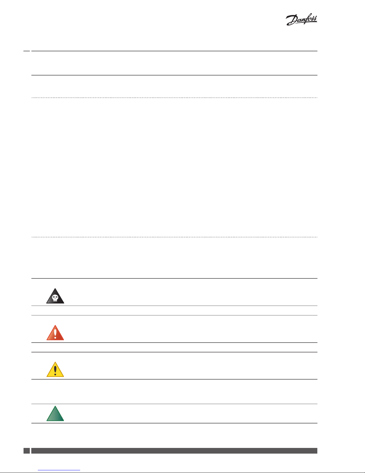
The instructions contain different warning symbols, which, together with text, indicate to the user that there are risks involved with ac-
tions to be taken.
The symbols are displayed to the left of the text and three different symbols are used to indicate the degree of danger:
Danger Indicates an immediate danger that leads to fatal or serious injury if
necessary measures are not taken.
Warning Risk of personal injury!
Indicates a possible danger that can lead to fatal or serious injury if
necessary measures are not taken.
Caution Risk of installation damage.
Indicates a possible hazard that can lead to item damage if necessary
measures are not taken.
A fourth symbol is used to give practical information or tips on how to perform a procedure.
N
Information regarding making the handling of the installation easier
or a possible operational technical disadvantage.
Installation Guide DHP-M
VIJSW102 Danfoss Heating Solutions
4
Page 5
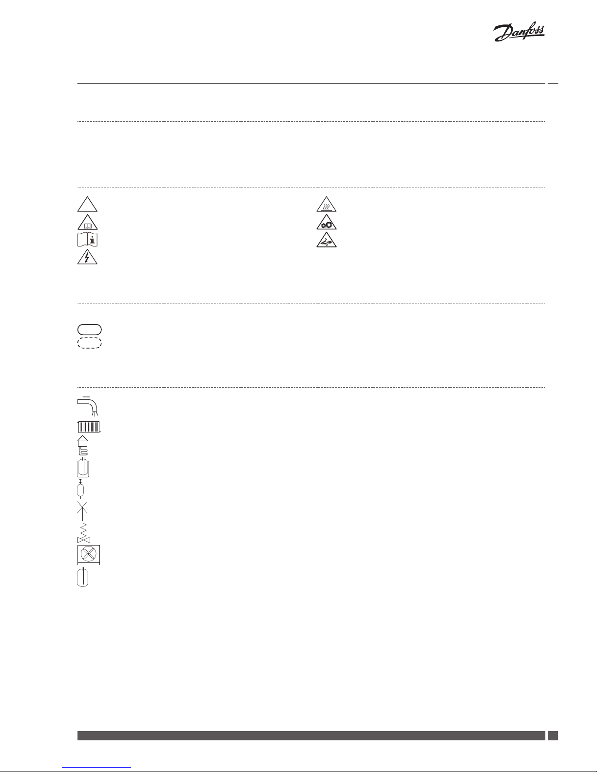
1.3 Symbols on decals
The following symbols can occur on decals on the different parts of the heat pump. Which symbols are used depends on the heat pump
model.
1.3.1 General
!
Warning, danger!
!
Read the documentation provided.
Read the documentation provided.
Warning, hazardous electrical voltage!
Warning, hot surfaces!
Warning, moving parts!
Warning, risk of crushing injury!
1.3.2 Electrical components
Explanation
Component, ordinary delivery according to proposed system solutions
Components, accessories according to proposed system solutions
1.3.3 Pipe connections
Tap water
Heating system
Brine system
Defrosting tank
Expansion tank with safety valve, brine
Air bleeding
Temperature and pressure relief valve
Outdoor unit
Water heater
Installation Guide
DHP-M
Danfoss Heating Solutions VIJSW102
5
Page 6
2 Important information/Safety instructions
2.1 General safety precautions
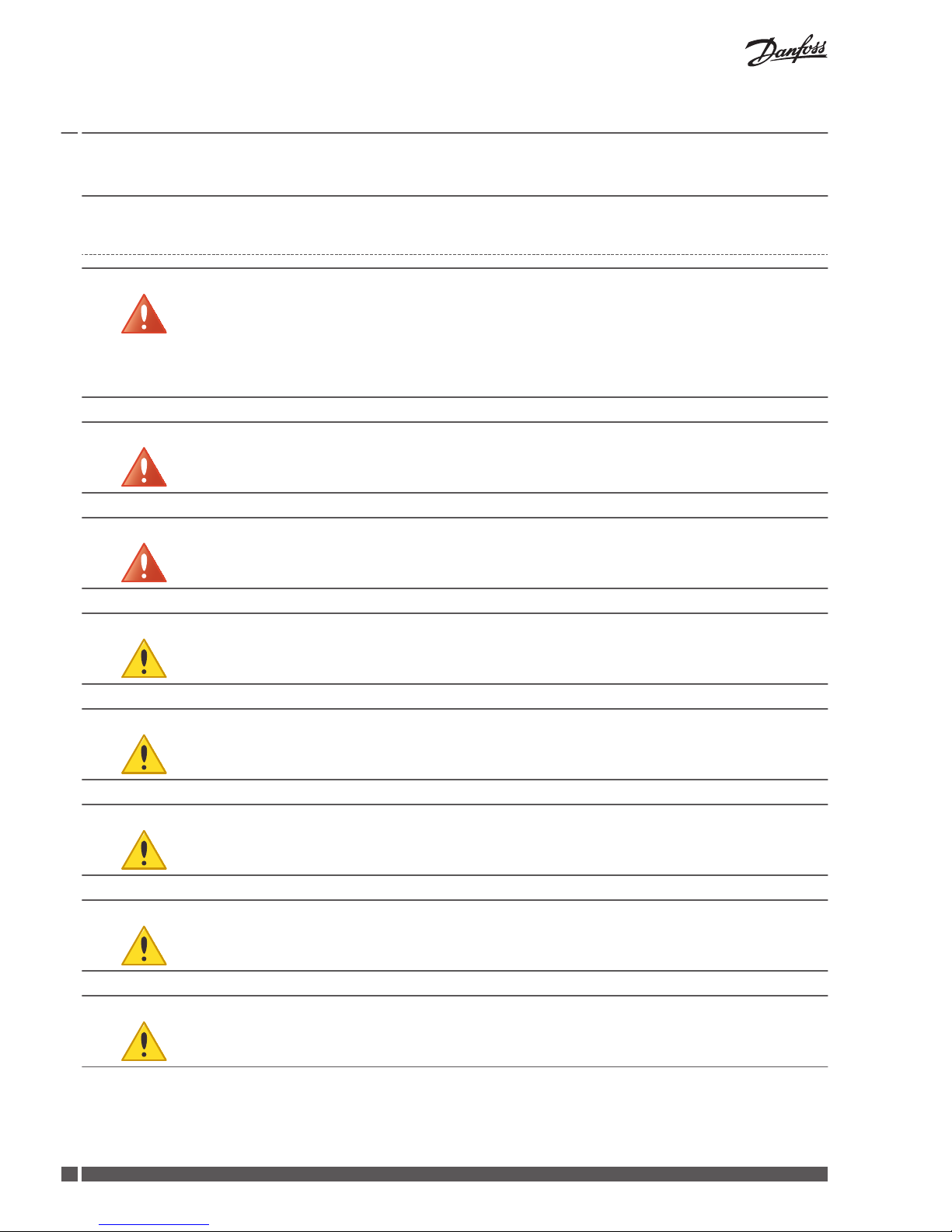
Warning This appliance can be used by children aged 8 years and above, and
by persons with reduced physical, sensory or mental capabilities or
lack of experience or knowledge, provided that they are supervised or
have been instructed in the safe use of the appliance and understand
the hazards involved. Children must not clean or carry out user maintenance on the appliance except under adult supervision.
Warning Ensure that children do not play with the product.
Warning The installation must only be carried out by a qualified installation en-
gineer, following applicable rules and regulations in addition to these
installation instructions.
Caution The heat pump must be located in a frost-free environment!
Caution Installation and connection should be carried out in accordance with
the instructions, in order to avoid subjecting local residents to noise
disturbance.
Caution The heating appliance should be placed on a stable surface that can
support the gross weight of the heating appliance.
Caution Before the heat pump is powered, you must ensure that the heating
system and coolant system, including the heat pump, are filled and
bled; otherwise, their circulation pumps may be damaged.
Caution If the electrician wishes to test the electrical connections before the
above is carried out, this should only be done after ensuring that the
heat transfer fluid pump and coolant pump are disconnected.
Installation Guide DHP-M
VIJSW102 Danfoss Heating Solutions
6
Page 7
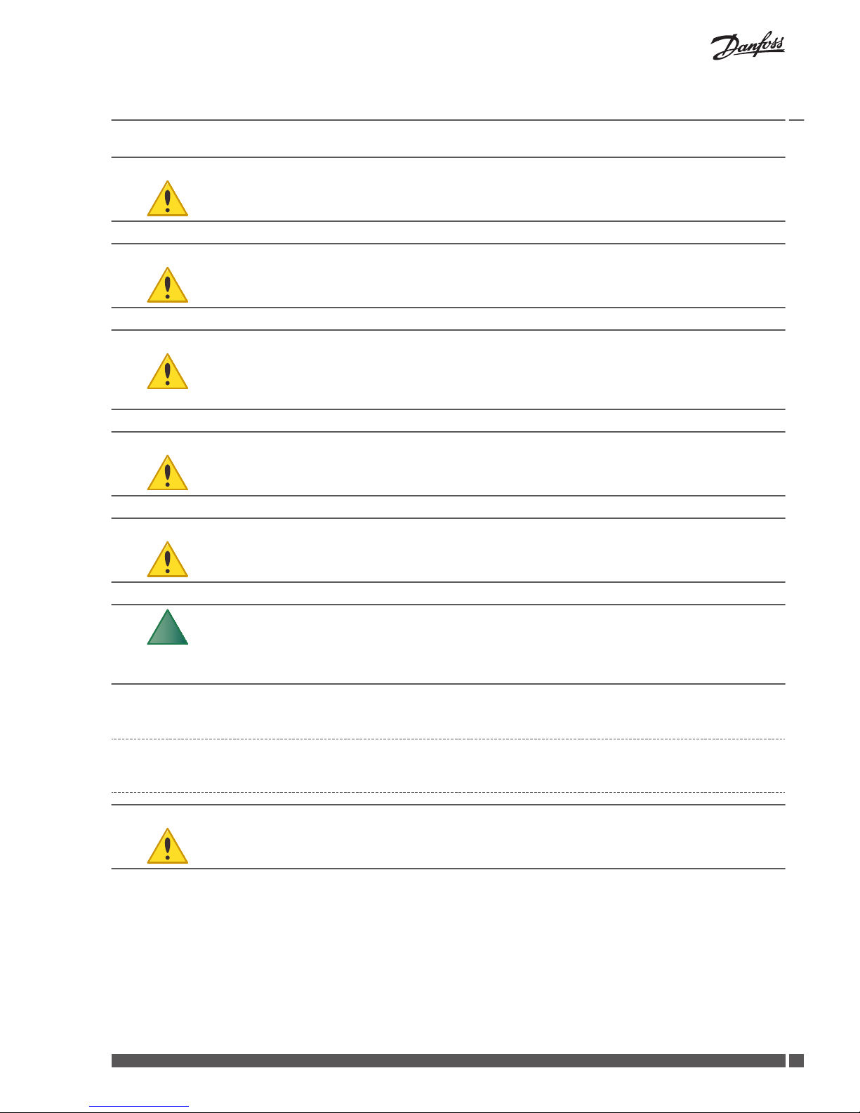
Caution When filling the coolant system the coolant pump must be operating;
you must ensure that the compressor and the heat transfer pump cannot start.
Caution This appliance is intended for use by expert or trained users in shops,
in light industry and on farms, or for commercial use by lay people.
Caution In accordance with EN60335-2-40, this product is classified as "not
available to the general public." This means that the product is designed to be handled by trained staff and installed in an engine room
or similar.
Caution Isolate the power supply to the heat pump while servicing the appli-
ance or replacing parts.
Caution Only spare parts approved by Danfoss Värmepumpar may be used for
this appliance.
N
In normal operation the heat pump generates noise and vibrations.
The appliance should be set up and connected in accordance with the
instructions in order to avoid noise being spread to noise-sensitive
areas.
2.2 Refrigerant
2.2.1 Refrigerant
Caution Work on the refrigerant circuit must only be carried out by a certified
refrigeration engineer.
Although the heat pump's refrigerant circuit is filled with a chlorine-free and environmentally-approved refrigerant that will not affect
the ozone layer, work on this system may only be carried out by authorised persons.
The refrigerant circuit is hermetically sealed and is subject to the EC regulation 517/201. According to EC regulation 517/2014, for heat
pumps containing 10 tonnes of CO2 equivalent or more, with hermetically sealed fluorinated greenhouse gases, an annual inspection of
leakage must be carried out by qualified personnel.
Installation Guide
DHP-M
Danfoss Heating Solutions VIJSW102
7
Page 8
2.2.2 Fire risk
The refrigerant is not combustible or explosive in normal conditions.
2.2.3 Toxicity
In normal use and normal conditions the refrigerant has low toxicity. Even though the toxicity of the refrigerant is low, it can cause injury
(or even death) in abnormal circumstances or if deliberately abused.
Warning Risk of personal injury! Spaces in which heavy vapor can collect below
the level of the air must be well ventilated.
Refrigerant vapour is heavier than air, and in enclosed spaces or in areas below the level of the door, for example, seepage can give rise
to high concentrations with a resultant risk of suffocation due to lack of oxygen.
Warning Risk of personal injury! Refrigerant exposed to a naked flame creates a
poisonous irritating gas. This gas can be detected by its odor even at
concentrations below its permitted levels. Evacuate the area until it
has been sufficiently ventilated.
2.2.4 Working on the refrigerant circuit
Caution When the refrigerant circuit is repaired, the refrigerant must not be re-
leased from the heat pump - it must handled appropriately.
Draining and refilling must only be carried out using new refrigerant (for the amount and type of refrigerant see manufacturer's plate)
through the service valves.
Caution All warranties will become void if a refrigerant, other than what Dan-
foss specifies, is used for refilling.
2.2.5 Scrapping
Caution When the heat pump is to be scrapped the refrigerant must be extrac-
ted for disposal. Local rules and regulations related to the disposal of
refrigerant must be followed.
Installation Guide DHP-M
VIJSW102 Danfoss Heating Solutions
8
Page 9
2.3 Electrical connection
Warning Hazardous electrical voltage! The terminal blocks are live and can
cause death through electric shock. All power supplies must be isolated before electrical installation is started. The heat pump is connected internally at the factory, for this reason electrical installation consists primarily of the connection of the power supply.
Caution Electrical installation may only be carried out by an authorized electri-
cian and must follow applicable local and national regulations.
Caution The electrical installation must be carried out using permanently rout-
ed cables and must follow applicable local and national regulations. It
must be possible to isolate the power supply using an all-pole circuit
breaker with a minimum contact gap of 3 mm.
2.4 Water quality
This heat pump and its components is developed to reliable and efficient work with water qualities in line with VDI 2035. In practice this
means that some general precautions should be taken:
As a heating system often contains small amounts of suspended solids (rust) and sludge products from calcium oxide, precaution should
be taken to ensure that the water in the heating system is as clean as possible to ensure long lasting performance and minimize the risk
of reliability issues. If magnetite can be expected in the heating system, cleaning of system and /or installation of magnetite filters
should always be considered. Any filters supplied with the heat pumps should always be installed. The dirt strainer should be fitted on
the return line from the heating system, as close to the heat pump as possible.
Chemical and/or oil contamination shall always be avoided.
In areas where there are exceptional water conditions with regards to hard water, a softening filter may be necessary to use/install (applies to heating system, hot water and brine circuit). The softening filter softens the water, cleans any impurities and prevents the buildup of calcification.
Installation Guide
DHP-M
Danfoss Heating Solutions VIJSW102
9
Page 10
3 Transport, unpacking and setting-up
3.1 Transporting the heat pump
Caution The heat pump must always be transported and stored upright in a
dry environment. Secure the heat pump so that it cannot tip over during transportation.
Caution If the heat pump is laid on the incorrect side it may become seriously
damaged, as the oil in the compressor may run out into the pressure
pipe and thereby prevent normal functioning.
3.1.1 Unpacking
1. Check that there are no transportation damages.
2. Remove the packaging.
3.1.2
Delivery check
Check that the delivery includes the following items:
Name
Quantity
Heat pump 1
Document set 1
Sound plate kit, 086L3375 (DHP-M XL and L)
Name Article number Quantity
Front and rear plate 086L3376 2
Left and right side plate 086L3377 2
Sensor kit, 086L3546 (in the electrical cabinet)
Name Article number Quantity
Outdoor sensor 086U3351 1
System supply line sensor 086L3356 1
3.2 Setting-up the heat pump
3.2.1 Recommended location
Positioning the heat pump
▪
The heat pump should preferably be placed against an outside wall (see chapter 'Heat pump data')
▪
Do not place the heat pump against walls facing noise-sensitive areas.
▪
Avoid placing the heat pump in the corner of a room.
Installation Guide
DHP-M
VIJSW102 Danfoss Heating Solutions
10
Page 11
▪
If possible, choose a location where the surfaces nearest the heat pump are soft. Avoid placing the heat pump close to large plastered or tiled areas.
▪
The heat pump is fitted with internal vibration insulation. However, the degree of vibration insulation achieved depends on the
bearing strength of the surface the heat pump stands on. In order to achieve adequate vibration insulation, the heat pump should
be placed on a concrete floor with a thickness of at least 100 mm, or another surface with equivalent characteristics.
▪
In order to minimise noise generation from the heat pump, the sound plate (included) should be fitted when the heat pump has
been put into position.
▪
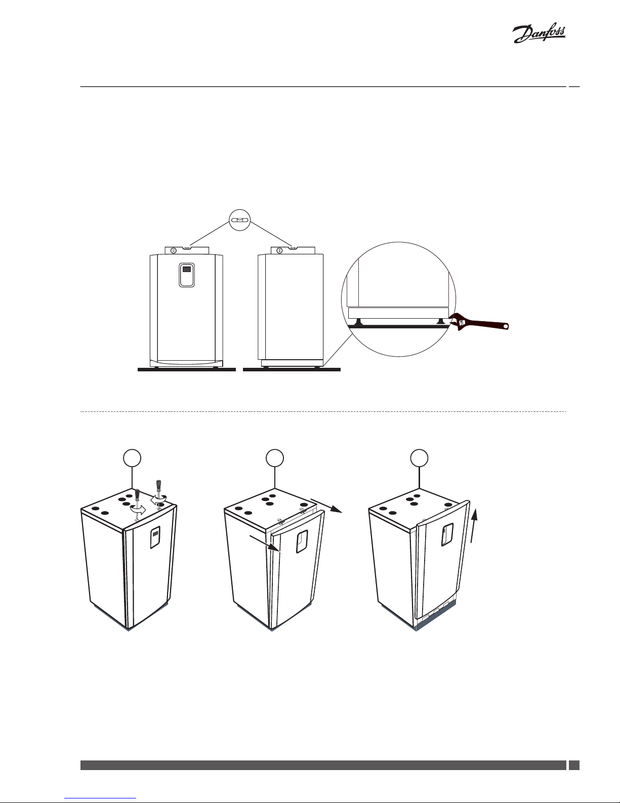
The heat pump must be level. Make sure to adjust feets in a way that the pump stands steady. If the feet is not adjusted correctly it
could cause some unwanted noise.
3.3 Dismantling the front cover
DHP-M XL and L
1 2 3
1. Turn the two locks on the top panel.
2. Push the front cover out by about 25 cm.
3. Lift the front upwards and lift off.
Installation Guide
DHP-M
Danfoss Heating Solutions VIJSW102
11
Page 12

DHP-M M and S
1
2
3
1. Press against the front cover and turn the catch 90° degrees anti-clockwise to release the front cover.
2. Tilt the front cover outwards.
3. Lift the front cover upwards to remove it from the heat pump.
Installation Guide
DHP-M
VIJSW102 Danfoss Heating Solutions
12
Page 13

4 Heat pump data
DHP-M L and XL
To facilitate the installation and subsequent testing and maintenance, there must be sufficient free space around the heat pump.
500 mm
500 mm
500 mm
500 mm
300 mm
756 mm
849 mm
686
543
488
178
129
245
50
10
10
166
181
321
656
702
314
134
761
900 mm
100 10 mm
1644 20, 0 mm
400 mm
Installation Guide DHP-M
Danfoss Heating Solutions VIJSW102
13
Page 14

DHP-M S and M
To facilitate the installation and subsequent testing and maintenance, there must be sufficient free space around the heat pump.
400
796
711
662
70 1010
692
1652
576
466
423
256
183
606
479
152
188
88
49
361,5
117,5
500 mm
500 mm
500 mm
500 mm
150 mm
Installation Guide DHP-M
VIJSW102 Danfoss Heating Solutions
14
Page 15

5 Components
DHP-M XL and L
12
13
14
15
10
16
17
18
19
20
21
22
23
24
1
2
4
6
5
3
9
8
7
11
The arrows show input to and output from the heat pump.
1. Return pipe, heating system
2. Supply pipe, heating system
3. Hot gas to water heater
4. Returning hot gas from water heater
5. Brine out
6. Brine in
7. Lead-in for incoming supply
8. Lead-ins for communication cable and sensor
9. Control panel
10. Inverter
11. Flexible hose
12. Hot gas exchanger
13. Service output, high pressure
14. High pressure transmitter
15. High pressure switch
16. Condenser pump
17. Condenser
18. Drying filter
19. Brine pump
20. Low pressure transmitter
21. Service outlet, low pressure
22. Evaporator
23. Compressor
24. Electronic expansion valve
DHP-M XL and L Connections, pipe diameter in mm
Brine Heating system Hot gas exchanger
54 42 28
Installation Guide DHP-M
Danfoss Heating Solutions VIJSW102
15
Page 16

DHP-M M and S
1
2
3
6
5
4
9
8
7
12
13
14
15
10
16
17
18
19
20
21
22
23
24
11
The arrows show input to and output from the heat pump.
1. Return pipe, heating system
2. Supply pipe, heating system
3. Hot gas to water heater
4. Returning hot gas from water heater
5. Brine out
6. Brine in
7. Lead-in for incoming supply
8. Lead-ins for communication cable and sensor
9. Control panel
10. Inverter
11. Flexible hose
12. Hot gas exchanger
13. Service output, high pressure
14. High pressure transmitter
15. High pressure switch
16. Condenser pump
17. Condenser
18. Drying filter
19. Brine pump
20. Low pressure transmitter
21. Service outlet, low pressure
22. Evaporator
23. Compressor
24. Electronic expansion valve
DHP-M M and S Connections, pipe diameter in mm
Brine Heating system Hot gas exchanger
42 35 28
Installation Guide DHP-M
VIJSW102 Danfoss Heating Solutions
16
Page 17

6 Piping installation
Caution To prevent leaks, ensure that there are no stresses in the connecting
lines
Caution Pipe installation must be carried out by an authorised installer
Caution Ensure that the pipe installation is carried out in accordance with the
dimensions and connection diagrams
Caution Bleed valves should be fitted if necessary
6.1 Safety valves
Warning Radiator systems with a closed expansion tank must also be equipped
with an approved manometer and safety valve. The safety valve
should be to a minimum of DN 20 and have a maximum of 6 bar opening pressure, or according to country-specific requirements.
Warning The overflow pipes from the safety valve must not be closed off. The
pipes should discharge into an outlet in a frost-free area.
Warning The connecting pipe between the expansion tank and the safety valve
must slope continuously upwards. A continuous upwards slope means
that the pipe must not slope downwards from the horizontal at any
point.
Caution Cold and hot water pipes and overflow pipes from safety valves must
be made of heat-resistant and corrosion-resistant material, e.g. copper.
Installation Guide DHP-M
Danfoss Heating Solutions VIJSW102
17
Page 18

6.2 Heating system supply pipe and return pipe
▪
Install a filter (max mesh size 0.7 mm) in the heating system's return pipe to protect the unit against foreign particles.
▪
Install the supply line with all the accompanying components.
▪
Ensure that the correctly dimensioned system pump is connected to the heating system's supply line, and connect the system
pump's control cables to the correct terminal block (see connection of system pump).
▪
Install the return line with all the accompanying components.
▪
Insulate the supply and return lines.
6.3 Noise information
To prevent disturbing noise from the heat pump the following recommendations should be observed:
▪
The heat pump's pipe connections cause vibration. In order to prevent this vibration spreading to the heating system and frame,
the pipes should be connected and laid with particular care.
▪
The brine and heat transfer fluid should normally be connected to the heat pump by means of a flexible hose.
▪
Pipes must not be attached to roofs or walls facing noise-sensitive areas.
▪
In cases where attachment of pipes to sensitive construction elements cannot be avoided, special elastic pipe attachments should
be used.
▪
Not correctly adjusted feet, can cause unwanted noise.
Installation Guide
DHP-M
VIJSW102 Danfoss Heating Solutions
18
Page 19

6.4 Connection brine
6.4.1 Drill holes for brine pipes
Caution Ensure that the holes for the insert pipes are positioned so that there is
room for the other installations.
Caution The brine pipes shall have separate lead-ins. If the wall lead-ins are be-
low the highest ground water level watertight lead-ins must be used.
The brine pipes must be insulated from the heat pump, through the walls and outside the house all the way to the collector so as to
avoid condensation and prevent heat loss.
If the brine pipes are to be routed above ground, drill holes in the walls for them.
If the brine pipes are to be routed below ground see the instructions below.
1
1
2
3
3
4
1. Insert pipe
2. Brine pipe
3. Mortar
4. Sealant
1. Drill holes in the wall for the insert pipes (1) for the brine pipes. Follow the dimension and connection diagrams. If there is any risk
of groundwater infiltration at brine pipe lead-ins, watertight grommets must be used.
2. Position the insert pipes (1) in the holes sloping downwards. The inclination must be at least 1cm every 30 cm. Cut them at an angle
(as illustrated) so that rain water cannot get into the pipes.
3. Insert the brine pipes (2) into the insert pipes in the installation room.
4. Fill in the holes around the lines with mortar (3).
5. Ensure that the brine pipes (2) are centered in the insert pipes (1) so that the insulation is distributed equally on all sides.
6. Seal the insert pipes (1) with a suitable sealant (foam) (4).
Installation Guide
DHP-M
Danfoss Heating Solutions VIJSW102
19
Page 20

6.4.2 Connection brine
DHP-M
▪
Install a filter (max. mesh size 0.7 mm) in the incoming brine pipe to protect the unit against foreign particles.
▪
Install the incoming brine pipe with all the accompanying components.
▪
Install the outgoing brine pipe with all the accompanying components.
▪
Fit both pipes with anti-diffusion condensation insulation.
▪
The expansion tank for brine is dimensioned in accordance with the manufacturer's instructions.
▪
Max. working pressure of heat source: 6 bar.
Installation Guide DHP-M
VIJSW102 Danfoss Heating Solutions
20
Page 21

7 Electrical installation
This equipment complies with IEC 61000-3-12 provided that the short-circuit power Ssc is greater than or equal to, see table, at the interface point between the user´s supply and the public system.
It is the responsibility of the installer or user of the equipment to ensure, by consultation with the distribution network operator if necessary, that the equipment is connected only to a supply with a short-circuit power Ssc greater than or equal to see table.
S
SC
S M L XL
MVA 2.1 2.1 2.4 3.2
The heat pump is connected internally at the factory, for this reason electrical installation consists mainly of the connection of the power
supply.
Danger Electrical voltage!
The terminal blocks are live and can be highly dangerous.
All power supplies must be switched off before the electrical installation is started.
Warning The electrical installation may only be carried out by an authorized
electrician and must follow applicable local and national regulations.
Warning The power cable may only be connected to the terminal block inten-
ded for this purpose.
No other terminal blocks may be used!
Caution The electrical installation must be carried out using permanently rout-
ed cables and must follow applicable local and national regulations.
Isolate the power supply using an all-pole circuit breaker with a minimum contact gap of 3 mm.
Installation Guide DHP-M
Danfoss Heating Solutions VIJSW102
21
Page 22

7.1 Electrical components
2
4
5
7
6
1
3
1. Terminal block row X1
2. Fuse F1
3. Fuse F2
4. EMC filter
5. Transformer
6. Terminal block row X2
7. I/O card
7.2
Fuse size
DHP-M
Heat pump
Unit S M L XL
400 V 3-N 50 Hz heat pump A C32 C40 C50 C63
7.3 Estimated current for DHP-M XL, L, M and S
Rad out oC
Estimated current (A) for XL
65 oC
* * * 51,4 51,8 52,3 *
60 oC
* * 52,5 53,1 53,5 54,0
54,2
1
55 oC
* 47,6 48,2 48,7 49,1 49,5 49,7
50 oC
42,9 43,7 44,2 44,7 45,0 45,4 45,7
45 oC
39,5 40,2 40,7 41,2 41,6 42,0 42,3
40 oC
36,6 37,3 37,9 38,3 38,8 39,3 39,7
35 oC
34,4 35,2 35,8 36,3 36,9 37,6 38,1
30 oC
33,1 33,9 34,6 35,3 36,0 36,9 37,5
Brine in oC
-10 -5 0 5 10 15 20
Installation Guide DHP-M
VIJSW102 Danfoss Heating Solutions
22
Page 23

1) Highest current
Rad out oC
Estimated current (A) for L
65 oC
* * * 38,9 39,4 39,4 *
60 oC
* * 38,5 39,4
39,8
1
39,8 39,5
55 oC
* 35,1 36,0 36,7 37,1 37,1 36,8
50 oC
32,2 32,9 33,6 34,2 34,5 34,6 34,4
45 oC
30,3 30,7 31,3 31,8 32,2 32,3 32,2
40 oC
28,4 28,7 29,2 29,7 30,1 30,4 30,4
35 oC
26,6 26,8 27,2 27,7 28,3 28,8 29,0
30 oC
25,0 25,0 25,4 26,0 26,8 27,5 27,9
Brine in oC
-10 -5 0 5 10 15 20
1) Highest current
Rad out oC
Estimated current (A) for M
65 oC
* * * 28,6 29,0 29,0 *
60 oC
* * 28,3 28,9
29,3
1
29,2 29,0
55 oC
* 25,7 26,4 26,9 27,2 27,2 27,0
50 oC
23,5 24,0 24,6 25,0 25,3 25,3 25,1
45 oC
22,0 22,4 22,8 23,2 23,5 23,6 23,5
40 oC
20,6 20,9 21,2 21,6 21,9 22,1 22,2
35 oC
19,3 19,4 19,7 20,1 20,5 20,9 21,1
30 oC
18,0 18,1 18,4 18,8 19,4 19,9 20,2
Brine in oC
-10 -5 0 5 10 15 20
1) Highest current
Rad out
o
C
Estimated current (A) for S
65 oC
* * * 24,9
25,2
1
25,2
1
24,8
60 oC
* * 22,8 23,2 23,4 23,3 23,0
55 oC
* 20,8 21,3 21,6 21,7 21,7 21,4
50 oC
19,0 19,5 19,9 20,1 20,3 20,3 20,1
45 oC
17,9 18,3 18,6 18,8 19,0 19,0 18,9
40 oC
16,9 17,1 17,4 17,6 17,8 18,0 18,0
35 oC
15,8 16,0 16,3 16,6 16,8 17,1 17,3
30 o C
14,8 15,0 15,2 15,6 15,9 16,3 16,8
Brine in oC
-10 -5 0 5 10 15 20
1) Highest current
Installation Guide
DHP-M
Danfoss Heating Solutions VIJSW102
23
Page 24

7.4 Connecting external supply voltage
7.4.1 Connect external supply voltage
Danger Electrical voltage! The power cable may only be connected to the ter-
minal block intended for this purpose. No other terminal block may be
used.
Caution A 400V heat pump can not be wired to work on a 230V power grid,
and vice versa. Make sure you follow the right wiring instructions, or it
can result in critical material damage.
The frequency converter has a high leakage current and must be earthed appropriately for safety reasons according to EN 61800-5-1.
The earth leakage current from the frequency converter exceeds 3,5 mA. Therefore is a good mechanical connection from the earth
cable to the earth connection important, the cross-section for the protective earthing conductor must be at least 10 mm ².
If the heat pump is connected to mains via a residual-current circuit breaker (RCCB). The RCCB should be of type B.
1. Remove the front cover from the heat pump.
2. Route the power cable through the opening in the top panel of the heat pump to the terminal blocks.
3. Localise terminal block row X1
4. Connect the power cables as follows.
7.4.2
Connection 400 V, 3-phase models
Isolator switch Terminal block X1 heat pump
Incoming cable
2
1
4
3
6
5
PE N L3 L2 L1
Installation Guide DHP-M
VIJSW102 Danfoss Heating Solutions
24
Page 25

7.5 Position and connect outdoor sensors
Recommended location -->
Unsuitable location -->
The outdoor sensor is connected by a two core cable. A maximum cable length of 50 m applies for a cross section of 0.75 mm2. For
greater lengths a cross section of 1.5 mm2 is used, up to a maximum of 120 m.
N
For high buildings, the sensor should be positioned between the second and third storeys. Its location must not be completely protected
from the wind but not in a direct draft. The outdoor sensor should not
be placed on reflective panel walls.
N
The sensor must be positioned at least 1 m from openings in the walls
that emit hot air.
N
If the sensor cable is connected through a pipe, the pipe must be
sealed so that the sensor is not affected by outgoing air.
N
The outdoor sensor must be of PT1000 type.
1. Position the outdoor sensor on the north or north west side of the house.
2. Connect the sensor to the heat pump’s control system.
50
8 9
7.6
Network connection, Online and setting up primary and secondary functionality
Danfoss Online
The heat pump is factory prepared for monitoring (and as an additional service being operated) remotely via internet. (Danfoss Online)
Installation Guide
DHP-M
Danfoss Heating Solutions VIJSW102
25
Page 26

In order to use the Danfoss Online service:
▪
Make sure that there is an available internet connection (router or equivalent) in the building
▪
An account and registration is required to use the Danfoss Online service.
For more information, see:
www.documentation.heatpump.danfoss.com
▪
Make a note of the heat pump MAC-address. The MAC-address is available in the Network menu in the display
Bear in mind that firewalls, deficient connections etc. can cause problems that will prevent desired functionality. Some operators, municipal networks etc. does not allow traffic through their firewalls.
Contact the internet service provider or network administrator if there are any such problems.
Connecting to internet
Connect the commissioned heat pump to an existing internet connection (router or equivalent). Use the RJ45 connection placed below
the display (CM module) behind the front panel. Use a patch cable (not cross over cable).
Example below with no external network connection (for installations with only one secondary unit):
(This solution will NOT provide internet functionality. See next example if internet functionality, or router solution, is desired)
Ethernet cable: Standard Cat 5 network cable, RJ 45.
1 2
1. Primary (controlling) heat pump with IP address e.g. 192.168.0.100
2. Secondary heat pump with IP address e.g. 192.168.0.101
Example below with external network connection (for installations with one or more secondary units):
3 4 5 6
1
2
8
7
1 Router/Switch
2 Possibility of internet access via router
3 Primary (controlling) heat pump with IP address e.g.
192.168.0.100
4 Secondary heat pump with IP address e.g. 192.168.0.101
5 Secondary heat pump with IP address e.g. 192.168.0.102
6 Secondary heat pump with IP address e.g. 192.168.0.103
X Secondary heat pump with IP address e.g. 192.168.0.XXX
7 Online Web server and database
8 Online web browser
Installation Guide
DHP-M
VIJSW102 Danfoss Heating Solutions
26
Page 27

7.7 Connecting bottom hot water sensor
53
16 17
7.8 Connecting top hot water sensor
55
18 19
7.9 Connecting system supply line sensor
51
10 11
The system supply sensor must always be installed on the system's supply line after the auxiliary heating. The sensor must be positioned
so that the hot water has been able to mix properly.
7.10 Connecting system pump
36
39 N
230 VAC
Start/stop of building's system pump 230 VAC.
7.11
Connecting hot gas pump with 230 V supply
34
48 49
34
48 49
Potential-free relay output, or connect jumper between terminal blocks 49-50, connect pump to terminal blocks 49, N and PE.
7.12
Connecting exchange valve for hot water
77
51 53 N
M
1
2
N
230 VAC
Installation Guide DHP-M
Danfoss Heating Solutions VIJSW102
27
Page 28

7.13 Connecting pressure sensor and/or flow sensor
436
26 27
7.14 Connecting EVU
437
28 29
7.15 Connection for external sum alarm
344
36 37
Potential-free relay output.
7.16 Connecting control signal (start/stop) for auxiliary heating
117
34 35
Potential-free relay output.
Connection 0-10V
72
24 25
▪
24V: Connect control signal to terminal block 24 and GND to terminal block 25. Power supply is drawn from terminal blocks 54-55,
56-57 or 58-59.
▪
230V: Power supply is drawn from terminal blocks 50 and N.
Installation Guide
DHP-M
VIJSW102 Danfoss Heating Solutions
28
Page 29

7.17 Connecting distribution circuit 1
107
22 23
Example 4-wire heat shunt and 3-wire heat shunt:
54 55 54 55
*When 55 is connected to G0, the 55 must be connected to G0 for all applications.
Installation Guide
DHP-M
Danfoss Heating Solutions VIJSW102
29
Page 30

7.18 Conversion table for sensors, PT-1000
When reading the resistance of the sensors, the sensor leads must first be disconnected from the control equipment. First measure the
sensor and cable. Then measure the sensor only.
°C ohms
-30 882
-20 921
-10 960
0 1000
10 1039
20 1078
30 1117
40 1155
50 1924
60 1232
70 1270
80 1309
90 1347
100 1385
110 1422
120 1460
130 1497
Installation Guide DHP-M
VIJSW102 Danfoss Heating Solutions
30
Page 31

8 Installation protocol and customer information
After installation and test operation, the customer must be informed about their new heat pump installation. In the User guide there is a
checklist regarding the information that the installer must give the customer.
N
The serial number must always be given for warranty matters.
Always make a note of the serial number in the installation protocol in
the User Guide.
8.1 Installation protocol
Fill in the Installation protocol in the User Guide.
Installation Guide
DHP-M
Danfoss Heating Solutions VIJSW102
31
Page 32

Installation Guide DHP-M
VIJSW102 Danfoss Heating Solutions
32
Page 33

Installation Guide DHP-M
Danfoss Heating Solutions VIJSW102
33
Page 34

Installation Guide DHP-M
VIJSW102 Danfoss Heating Solutions
34
Page 35

Installation Guide DHP-M
Danfoss Heating Solutions VIJSW102
35
Page 36

Installation Guide DHP-M
Danfoss Heat Pumps
Box 950
SE 671 29 ARVIKA
Phone +46 570 81300
E-mail: dhpinfo@danfoss.com
Internet: www.heating.danfoss.com
Danfoss can accept no responsibility for possible errors in catalogues, brochures and other printed material. Danfoss reserves the right to alter its products without notice. This also applies to products
already on order provided that such alterations can be made without subsequential changes being necessary in specifications already agreed. All trademarks in this material are property of the respective
companies. Danfoss Heating Solutions and the Danfoss Heating Solutions logotype are trademarks of Danfoss A/S. All rights reserved.
VIJSW102 Produced by Danfoss Heating Solutions © 2017
 Loading...