


MAKING MODERN LIVING POSSIBLE
Installation Guide
DHP-iQ
www.heating.danfoss.com

Danfoss A/S is not liable or bound by warranty if these
instructions are not adhered to during installation or service.
The English language is used for the original instructions.
Other languages are a translation of the original instructions.
(Directive 2006/42/EC)
© Copyright Danfoss A/S

Table of Contents
1 About documents and decals ........................................................ 5
1.1 Introduction ................................................................ 5
1.2 Symbols in documents .......................................................... 5
1.3 Symbols on decals ............................................................ 6
1.3.1 General .................................................................... 6
1.3.2 Electrical components .......................................................... 6
1.3.3 Pipe connections ............................................................. 6
2 Important information/Safety regulation ................................................ 7
2.1 General safety precautions ....................................................... 7
3 Heat pump data ................................................................. 11
3.1 Heat pump data, dimensions and connections .......................................... 11
3.1.1 Description outdoor unit ........................................................ 11
3.1.2 Description indoor unit ......................................................... 12
3.1.3 Technical data, outdoor unit, ..................................................... 12
3.1.4 DHP-iQ System solution ......................................................... 14
4 Transporting, unpacking and setting-up ................................................ 20
4.1 Transporting the heat pump ...................................................... 20
4.2 Unpacking ................................................................. 20
4.2.1 Unpack the heat pump ......................................................... 20
4.2.2 Delivery check ............................................................... 21
4.3 Installing the unit ............................................................. 21
4.3.1 Check list before installing ....................................................... 22
4.3.2 Heat pump foundation ......................................................... 23
4.3.3 Outdoor unit support .......................................................... 23
4.3.4 Drain work ................................................................. 24
4.3.5 Select a location in windy areas .................................................... 27
4.4 Outdoor unit installation ........................................................ 27
4.5 Noise information ............................................................. 28
4.5.1 Installation of the heat pump ..................................................... 28
4.5.2 Flexible hoses ............................................................... 28
4.6 Positioning the heat pump ....................................................... 28
4.6.1 Space requirements for outdoor unit ................................................. 30
4.7 Removing the front cover ........................................................ 33
5 Piping installation ................................................................ 34
5.1 Water volume in heating system ................................................... 35
5.1.1 Flow switch installation ......................................................... 35
5.1.2 Charging water .............................................................. 36
5.2 Minimum flow in the heating system ................................................ 37
5.3 Safety valves ................................................................ 38
5.4 Connection heating and hot water .................................................. 38
5.4.1 Connect cold and hot water lines ................................................... 38
5.4.2 Connect the heating system supply and return lines ....................................... 38
5.5 Piping work ................................................................. 39
5.5.1 Flushing and air-purging ........................................................ 39
5.5.2 Pressure relief valve ............................................................ 40
5.5.3 Filter / Strainer ............................................................... 40
5.5.4 Piping insulation .............................................................. 40
5.6 Water quality ................................................................ 40
6 Electrical Installation .............................................................. 42
6.1 How to unmount the outdoor unit electrical cabinet ...................................... 44
6.2 Electrical connection points ...................................................... 45
6.3 Flow switch connection ......................................................... 45
6.4 Indoor unit ................................................................. 46
6.4.1 Installation ................................................................. 46
6.4.2 DHP-iQ Mini electrical components in the indoor unit ...................................... 46
6.4.3 DHP-iQ Maxi electrical components in the indoor unit ..................................... 46
6.5 Cable connections ............................................................ 47
6.7 Supply and return pipe sensor connection ............................................. 47
Installation Guide DHP-iQ
Danfoss Heating Solutions VIJSS102
3

6.8 Supply line sensor distribution circuit 1 connection ....................................... 47
6.9 Sensors to external water heater connection ............................................ 48
6.10 Room sensor connection ........................................................ 48
6.11 System circulation pump connection ................................................ 48
6.12 Circulation pump and distribution circuit 1 connection ..................................... 48
6.13 Communication cable connection .................................................. 49
6.14 Power supply connection ........................................................ 49
6.15 Swimming pool sensor connection .................................................. 50
6.16 Distribution circuit 2 sensor connection ............................................... 50
6.17 Wiring .................................................................... 50
6.17.1Between indoor unit and outdoor unit connection cable specifications (Common in use) ............... 51
6.17.21 Phase terminal block spec ...................................................... 51
6.17.33-phase terminal block spec ...................................................... 52
6.17.4Connecting the power terminal .................................................... 52
7 Check list ...................................................................... 53
7.1 Checking the piping installation .................................................... 53
7.1.1 Check list before commissioning the unit .............................................. 54
7.2 Checking the electrical installation .................................................. 54
Installation Guide DHP-iQ
VIJSS102 Danfoss Heating Solutions
4
1 About documents and decals
1.1 Introduction
The following documents are available for this product:
▪
The Installation Quick Guide is an illustrated step-by-step guide on how to install the heat pump.
Supplied with the heat pump on delivery.
▪
Installation Guide. Complements the Installation Quick Guide and gives thorough information on how to install the heat pump.
Available for download, see below.
▪
The Commissioning Guide contains the required information in order to commission the heat pump and tune the heating system.
Available for download, see below.
▪
The Wiring Diagrams for the heat pump intended for fault tracing and service.
Available for download, see below.
▪
The User Guide is intended for the end user and must be handed over and gone through with the end user when installation and
commissioning is completed.
Supplied with the heat pump on delivery.
▪
Country specific instructions and forms are available where relevant.
Supplied with the heat pump on delivery.
▪
Self-adhesive decals with translation text. Must be placed on the manufacturing plate in conjunction with installation.
Supplied with the heat pump on delivery.
Documents not delivered with the heat pump are available for download here:
www.documentation.heatpump.danfoss.com
1.2
Symbols in documents
The instructions contain different warning symbols, which, together with text, indicate to the user that there are risks involved with actions to be taken.
The symbols are displayed to the left of the text and three different symbols are used to indicate the degree of danger:
Danger Indicates an immediate danger that leads to fatal or serious injury if
necessary measures are not taken.
Warning Risk of personal injury!
Indicates a possible danger that can lead to fatal or serious injury if
necessary measures are not taken.
Caution Risk of installation damage.
Indicates a possible hazard that can lead to item damage if necessary
measures are not taken.
A fourth symbol is used to give practical information or tips on how to perform a procedure.
N
Information regarding making the handling of the installation easier
or a possible operational technical disadvantage.
Installation Guide DHP-iQ
Danfoss Heating Solutions VIJSS102
5
1.3 Symbols on decals
The following symbols can occur on decals on the different parts of the heat pump. Which symbols are used depends on the heat pump
model.
1.3.1 General
!
Warning, danger!
!
Read the documentation provided.
Read the documentation provided.
Warning, hazardous electrical voltage!
Warning, hot surfaces!
Warning, moving parts!
Warning, risk of crushing injury!
1.3.2 Electrical components
Explanation
Component, ordinary delivery according to proposed system solutions
Components, accessories according to proposed system solutions
1.3.3 Pipe connections
Tap water
Heating system
Expansion tank with safety valve, brine
Air bleeding
Temperature and pressure relief valve
Outdoor unit
Water heater
Installation Guide
DHP-iQ
VIJSS102 Danfoss Heating Solutions
6
2 Important information/Safety regulation
2.1 General safety precautions
Carefully follow the precautions listed as below because they are essential to guarantee the safety of Danfoss product. Store the manual
in a safe place in order to be able to use it as reference after installation. Remember to hand it over to the new owner if the heat pump
unit is sold or transferred. To prevent serious damage on the system and injuries to users, precautions and other notices shall be observed.
Danger Risk of personal injury! Children are not permitted to play with the
product.
Danger Always disconnect a power supply of heat pump before servicing it or
accessing components inside the unit. (Have in mind that electrical
current is stored for a while in the condensator after you disconnect
the power supply)
Warning Verify that installation and testing operations must be performed by
qualified personnel.
Caution This manual explains how to install the air/water heat pump. The use
of other types of units with different control systems may damage the
units and invalidate the warranty. The manufacturer shall not be responsible for damages arising from the use of non compliant units.
Warning The manufacturer shall not be responsible for damage originating
from unauthorized changes or the improper connection of electric
and hydraulic lines. Failure to comply with these instructions or to
comply with the requirements set forth in the “Operating limits” table,
included in the manual, shall immediately invalidate the warranty.
Warning Do not use the units if you see some damages on the units, hear loud
noise, or the smell of burning.
Warning If the unit produces smoke, is very noisy or if any of the cables are hot
or damaged, always use the protection switch to turn off the unit and
contact the heat pump supplier.
Installation Guide DHP-iQ
Danfoss Heating Solutions VIJSS102
7
Warning Always remember to inspect the unit, electric connections, refrigerant
tubes and protections regularly. These operations shall be performed
by qualified personnel only.
Warning The unit contains moving parts and electrical parts, which should al-
ways be kept out of the reach of children.
Warning Do not attempt to repair, move, alter or reinstall the unit by unauthor-
ized personnel, these operations may cause product damage, electric
shocks and fires.
Warning Do not touch the internal parts (water pipes, refrigerant pipes, heat ex-
changers, etc) while running the units. And if you need to adjust and
touch the units, have enough time for the unit to be cooled off and be
sure to wear protective gloves.
Warning In case of refrigerant leakage, try to avoid getting in contact with the
refrigerant because this could result in severe wounds.
Caution Inspect the product shipped and check if damaged during transport. If
the product has some damages, DO NOT INSTALL and immediately
discuss about the damages with the carrier or retailer (if the installer or
the authorized technician has collected the material from the retailer.)
Caution Always make sure that the power supply is compliant with local safety
standards.
Caution Install the power cable and communication cable of the indoor and
outdoor unit at least 1m away from the electric appliance.
Caution Protect the unit from rats or small animals. If an animal makes a con-
tact with the electric parts, it can cause malfunctions, smoke or fire.
Please instruct the customer to keep the area around the unit clean.
Installation Guide DHP-iQ
VIJSS102 Danfoss Heating Solutions
8
Caution Do not disassemble and alter the heater at your own discretion.
Caution For the UK market only:
Read the UK-specific appendix to Installation instructions before starting
any installation work!
Caution The heat pump must be installed by authorised installation engineers
and the installation must follow the applicable local rules and regulations as well as these installation instructions.
Caution This appliance can be used by children aged from 8 years and above
and persons with reduced physical, sensory or mental capabilities or
lack of experience and knowledge if they have been given supervision
or instruction concerning use of the appliance in a safe way and understand the hazards involved. Cleaning and user maintenance shall
not be made by children without supervision.
Caution Make sure you wait before performing any work in the heat pump af-
ter turning off the power, because the unit contains capacitors which
may be charged.
Caution If there is a water heat tank it must be placed in an area with a floor
drain.
Caution The heat pump must be located on a stable base. The floor must be
able to support the gross weight of the heat pump with filled hot water tank. (DHP-iQ Maxi)
N
It is important that the heating system is bled after installation.
N
Bleed valves must be installed where necessary.
Installation Guide DHP-iQ
Danfoss Heating Solutions VIJSS102
9
Caution The hot water tank must be equipped with an approved safety valve.
(DHP-iQ Maxi)
Caution Heating systems with closed expansion tanks must also be supplied
with approved pressure gauges and safety valves.
Caution Cold and hot water pipes and overflow pipes from safety valves must
be made of heat resistant and corrosion-resistant material, for example copper. The safety valve overflow pipes must have an open connection to the drain and visibly flow into this in a frost-free environment.
Caution Do not start the unit ( DHP-iQ Maxi) if there is a possibility of frozen
water in the immersion heater.
Caution When cooling, it is important to limit the lowest flow line temperature
to prevent condensation.
Installation Guide DHP-iQ
VIJSS102 Danfoss Heating Solutions
10
3 Heat pump data
3.1 Heat pump data, dimensions and connections
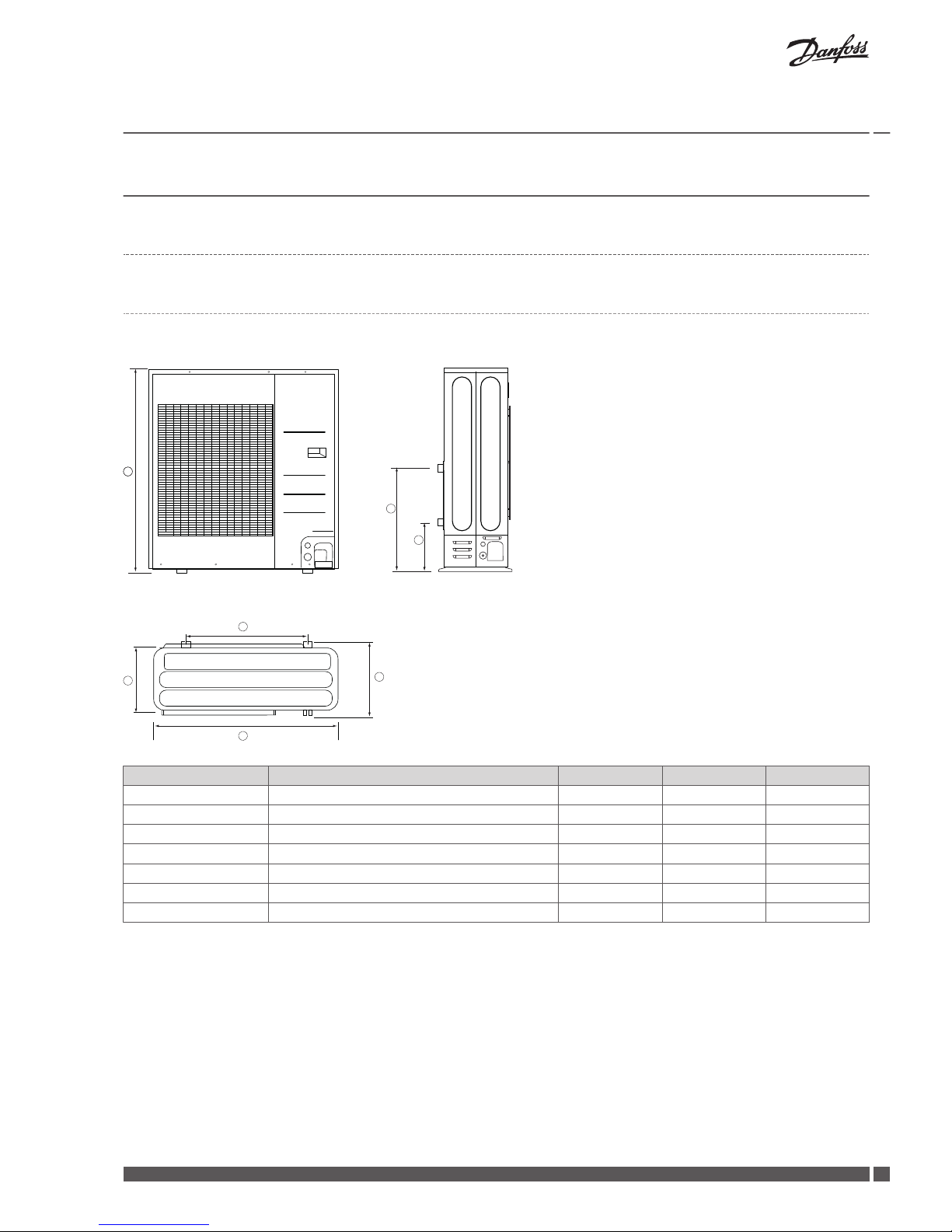
3.1.1 Description outdoor unit
DHP-iQ
6
5
7
2
3
1
4
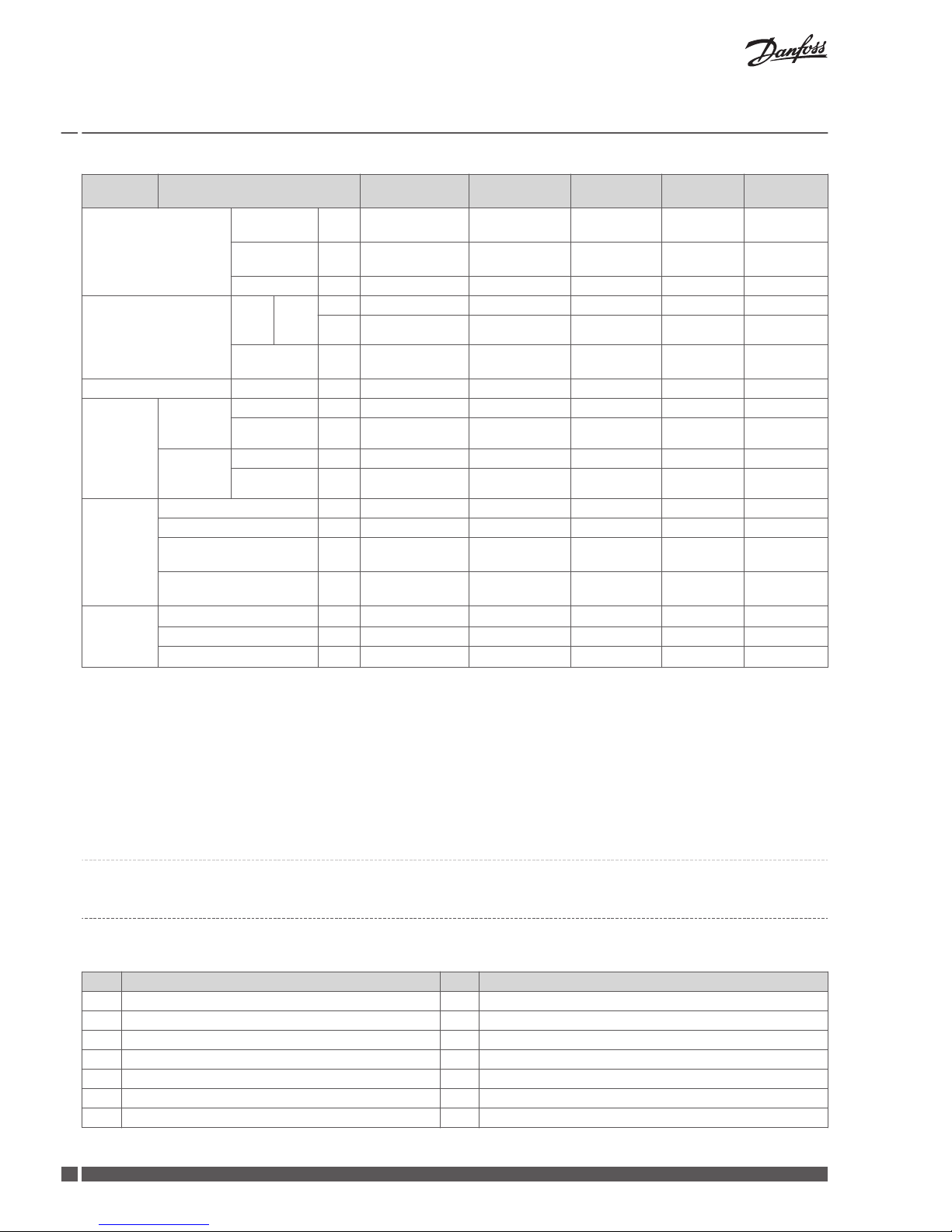
Position Description outdoor unit 5kW 9 kW 16kW
1 Width 880 mm 940 mm 940 mm
2 Depth 310 mm 330 mm 330 mm
3 Distance between feets 660 mm 620 mm 620 mm
4 Height
798
mm
998 mm 1420 mm
5 Height to supply line pipe 497 mm 513,4 mm 151,5 mm
6 Height to return line pipe 227 mm 244,4 mm 83,5 mm
7 Depth with protruding feets 364 mm 384 mm 384 mm
Installation Guide DHP-iQ
Danfoss Heating Solutions VIJSS102
11
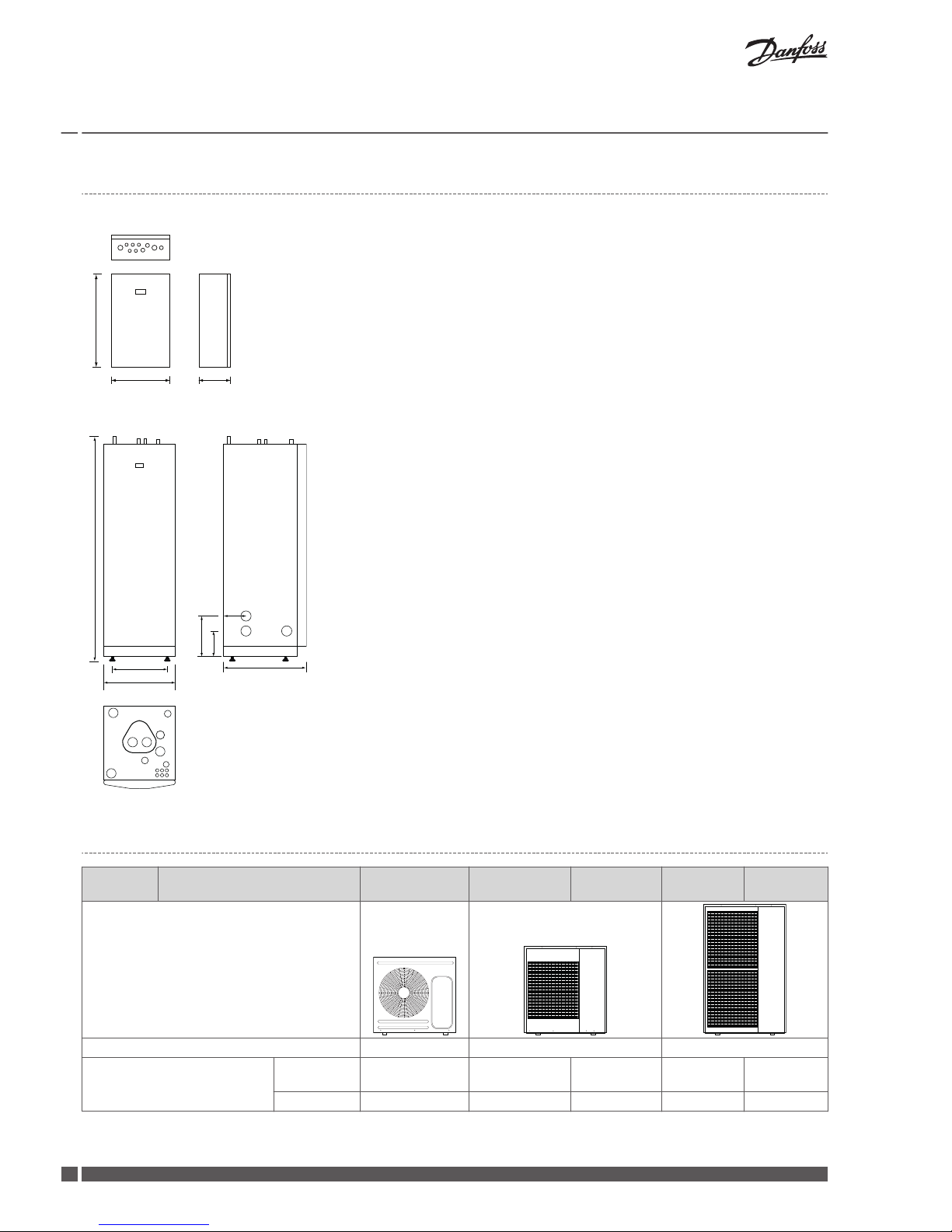
3.1.2 Description indoor unit
Indoor unit DHP-iQ Mini
600
380
204
1
1. Lead-in for supply, sensor and communication cables
Indoor unit DHP-iQ Maxi
1845 ±10
596
455
690
1
2
3
4
5
125
210
330
6
7
8
9
10
1. Supply line heating system,28 mm Cu
2. Return line heating system,28 mm Cu
3. Connection for bleed valve,22 mm Cu
4. Hot water line,22 mm Cu
5. Cold water line,22 mm Cu
6. Lead-in for supply, sensor and communication cables
7. Supply or return line heat pump
8. Supply or return line heat pump
9. Extra knock-out
10. Safety valve for temperature and pressure (only applies to certain models)
Position 7 and 8 can be connected to either the left or right-hand side or at the bottom of the
control unit.
3.1.3
Technical data, outdoor unit,
Item
1phase 5kW 1phase 9kW 3phase 9kW 1phase
16kW
3phase 16kW
Outdoor unit
Mode Heat Pump (A2W) Heat Pump (A2W) Heat Pump (A2W)
Water heater energy efficiency
(Average climate A +7 )
Energy class,
XL cycle A A A A A
NWH (%) 108 89 89 80 80
Installation Guide DHP-iQ
VIJSS102 Danfoss Heating Solutions
12

Item
1phase 5kW 1phase 9kW 3phase 9kW 1phase
16kW
3phase 16kW
Performance (A7/
W35)
*1
Nominal
Capacity
(Min/Std/
Max)
Heating kW 1.667 / 5.00 / 5.00 2.20 / 9.00 / 9.00 2.20 / 9.00 /
9.00
3.75 / 16.00 /
16.00
3.75 / 16.00 /
16.00
Btu/h 5,700 / 17,100 /
17,100
7,500 / 30,700 /
30,700
7,500 /
30,700 /
30,700
12,800 /
54,600 /
54,600
12,800 /
54,600 /
54,600
Cooling kW 1.625 / 5.00 / 5.00 1.75 / 7.50 / 7.50 1.75 / 7.00 /
7.00
3.30 / 14.00 /
14.00
3.30 / 14.00 /
14.00
Btu/h 5,500 / 17,100 /
17,100
6,000 / 25,600 /
25,600
6,000 /
23,900 /
23,900
11,300 /
47,800 /
47,800
11,300 /
47,800 /
47,800
Power Input(Nominal)
(Min/Std/
Max)
Heating kW 0.348 / 1.06 / 1.06 0.49 / 2.14 / 2.14 0.49 / 2.14 /
2.14
0.809 / 3.80 /
3.80
0.809 / 3.80 /
3.80
Cooling 0.438 / 1.21 / 1.21 0.48 / 1.95 / 1.95 0.48 / 1.92 /
1.92
0.853 / 3.84 /
3.84
0.853 / 3.84 /
3.84
Current Input(Nominal)
(Min/Std/
Max)
Heating A 1.6 / 5.1 / 5.1 2.3 / 9.2 / 9.2 0.8 / 3.5 / 3.5 3.7 / 17.1 /
17.1
1.3 / 5.7 / 5.7
Cooling 2.0 / 5.7 / 5.7 2.2 / 9.0 / 9.0 0.8 / 3.2 / 3.2 3.9 / 17.3 /
17.3
1.3 / 5.8 / 5.8
COP (Nominal Heating) 4.72 4.21 4.21 4.21 4.21
EER (Nominal Cooling) 4.13 3.85 3.65 3.65 3.65
SCOP (35℃) 4,50 4.41 4.41 4.41 4.41
ESEER 5,29 5.07 4.69 4.92 4.92
Performance (A2/
W35)
*2
Capacity Heating W 4,500 7,000 7,000 12,500 12,500
COP 3.46 3.00 3.00 3.10 3.10
Performance (A-7/
W35)
*3
Capacity Heating W 7,700 7,600 7,600 13,400 13,400
COP 2,69 2.39 2,39 2.47 2.47
Field Wiring
Power Source Wire ㎡ L<10m, 2.5↑
10m<L<20m, 4.0↑
4.0↑ 1.5↑ 6.0↑ 1.5↑
Transmission Cable ㎡ 0.75↑ 0.75↑ 0.75↑ 0.75↑ 1.5↑
Water Connections
Water Flow Rate (Heating/
Cooling)
LPM 14.5/14.5 26/22 26/21 46/40 46/40
Water Pressure (Max) bar 3 3 3 3 3
Water Pipe Inlet Φ,
inch
BSPP male 1" BSPP male 1" BSPP male 1" BSPP male 1" BSPP male 1"
Outlet Φ,
inch
BSPP male 1" BSPP male 1" BSPP male 1" BSPP male 1" BSPP male 1"
Leaving
Water Temperature
Heating °C 25~55 25~55 25~55 25~55 25~55
Cooling °C 5~25 5~25 5~25 5~25 5~25
Refrigerant
Type (GWP 2088)
*8
- R410A R410A R410A R410A R410A
Control Method - EEV INCLUDED EEV INCLUDED EEV INCLUDED EEV INCLU-
DED
EEV INCLUDED
Factory Charging (CO2
equivalent)
g 1150 (2401) 1400 (2923) 1500 (3132) 2600 (5428) 2600 (5428)
Power Supply
Φ, #,
V, Hz
E(220~240V,
50Hz, 1Ф)
E(220~240V,
50Hz, 1Ф)
G(380~415V,
50Hz, 3Ф)
E(220~240V,
50Hz, 1Ф)
G(380~415V,
50Hz, 3Ф)
Installation Guide DHP-iQ
Danfoss Heating Solutions VIJSS102
13
Item
1phase 5kW 1phase 9kW 3phase 9kW 1phase
16kW
3phase 16kW
Compressor
Type BLDC Twin Rotary BLDC Twin Rota-ryBLDC Twin Ro-
tary
BLDC Twin
Rotary
BLDC Twin
Rotary
Model UG4TH200FUAE4 UG8TH8265FJW UG8T300FUC-JUUG5T450FU UG5T450FU
Oil POE POE PVE PVE PVE
Fan
Air
Flow
Rate
Cooling
CMM 51 66 66 118 118
l/s 850 1100 1100 1967 1967
Number of
Unit
EA 1 1 1 2 2
Base Heater W N/A 150 150 150 150
Sound
*4
4A
Sound
Pressure
Level
Heating dB(A) 45 48 48 52 52
Cooling dB(A) 45 48 48 54 54
4B
Sound
Power Level
Heating dB 61 63 63 66 66
Cooling dB 62 64 64 69 69
External Dimension
Net Weight kg 59 76.0 76.0 108.0 108.0
Shipping Weight kg 63 84.0 84.0 118.0 118.0
Net Dimensions (WxHxD) mm 880 x 798 x 310 940 x 998 x 330 940 x 998 x
330
940 x 998 x
330
940 x 998 x
330
Shipping Dimensions
(WxHxD)
mm 1,023 x 904 x 413 995 x 1,178 x
426
995 x 1,178 x
426
995 x 1,178 x
426
995 x 1,178 x
426
Operating
Temp.
Range
Heating
*5
℃ -25~35 -25~35 -25~35 -25~35 -25~35
Cooling ℃ 10~46 10~46 10~46 10~46 10~46
DHW Tank
*6
℃ -25~35 -25~35 -25~35 -25~35 -25~35
*1)
A2W Condition #1 : (Heating) Water In/Out 30°C/35°C, Outdoor Air DB/WB 7°C/6°C; (Cooling) Water In/Out 23°C/18°C, Outdoor Air DB 35°C.
*2)
A2W Condition #2 : (Heating) Water In/Out */
35°C, Outdoor Air DB/WB 2°C/1°C
*3)
A2W Condition #3 : (Heating) Water In/Out */35°C, Outdoor Air DB/WB -7°C/-8°C
*4)
A) Sound Pressure was acquired in an anechoic room. Thus actual noise
level may be different depending on the installation conditions. B) Sound Power Level, Nominal operation.
*5)
At the temperature -25°C ~ -20°C, operation is available but capacity cannot be
guaranteed.
*6)
Heat pump operating range of DHW : -25°C ~ 35°C.
*7)
These products contain R410A which is fluorinated greenhouse gas.
*8)
According to F-gas directive EC 517/2014
※ Heat Exchanger type : Condensor - Fin & Tube (Fin : Al, Tube : Cu), Plate Heat Exchanger(PHE) (STS)
3.1.4
DHP-iQ System solution
Symbol key
The following symbol key applies to all system solutions:
Pos
Description Pos Description
5 Heat pump unit 83 Non-return valve
10 Supply line 85 Air bleeding valve
11 Return line 87 Safety valve (9 bar, WW)
12 Cold water 91 Dirt strainer with shut-off valve
13 Hot water 96 Flexible hose
18 Hot water storage tank 100 Security valve (1.5 bar)
21 Volume tank 101 Reversing valve pool
Installation Guide DHP-iQ
VIJSS102 Danfoss Heating Solutions
14
Pos Description Pos Description
33 Circulation pump (shunt additional heater) 103 Pool heater exchanger
36 System circulation pump 107 Shunt valve (distribution circuit 1)
40 Control unit 108 Supply line sensor (distribution circuit 1)
50 Outdoor sensor 109 Circulation pump (distribution circuit 1)
51 System supply line sensor 112 Expansion vessel (hot gas)
52 Return line sensor 114 Immersion heater
55 Hot water sensor top TWC 117 External auxiliary heater
60 Sensor pool 120 Fan coil
62 Room sensor 133 Shunt valve (distribution circuit 2)
71 Flow switch 134 Supply line sensor (distribution circuit 2)
72 Shunt for additional heat 135 Circulation pump (distribution circuit 2)
77 Diverting valve hot water 170 System circulation pump A
79 Reversing valve cooling tank 405 Heating out sensor
80 Shut-off valve
Installation Guide DHP-iQ
Danfoss Heating Solutions VIJSS102
15

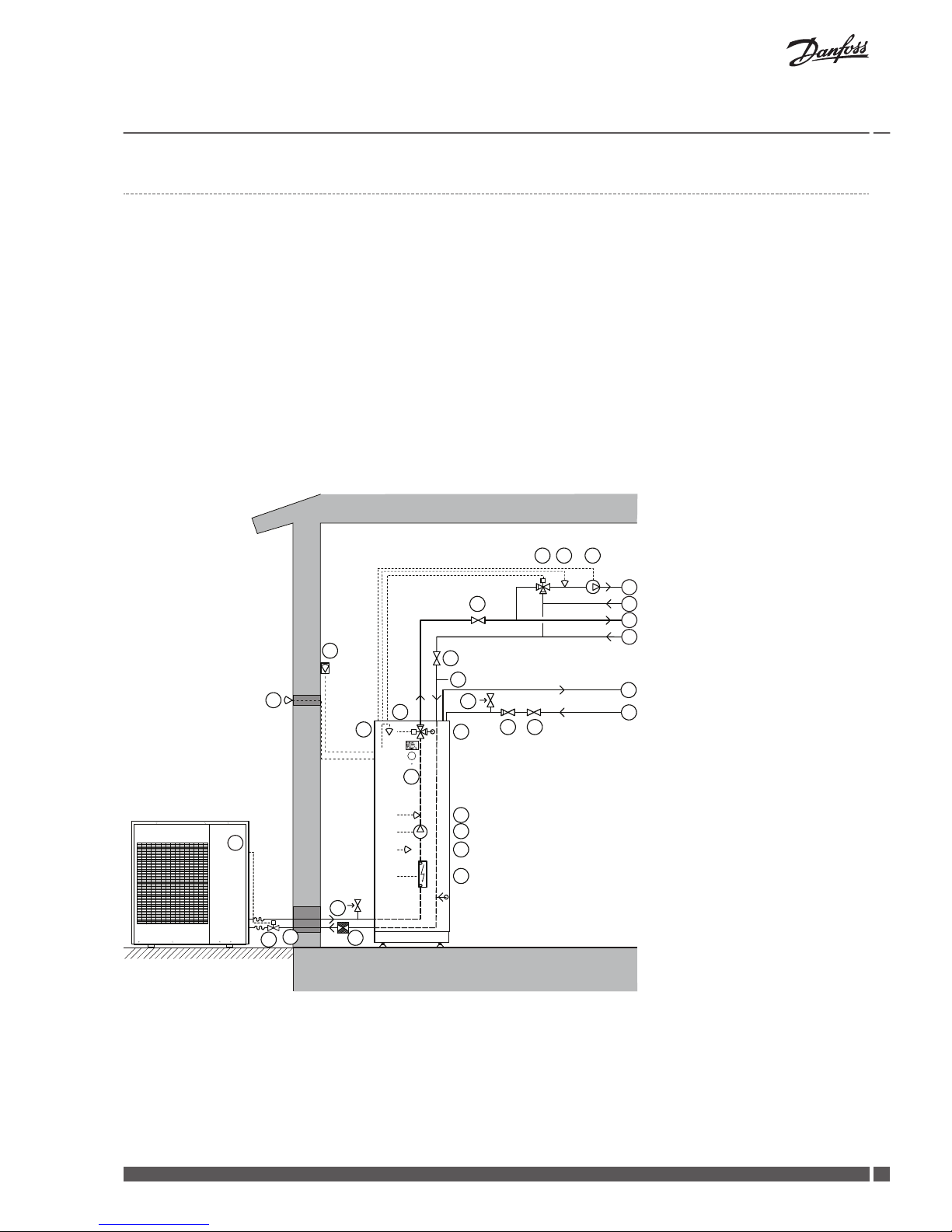
System solution DHP-iQ Mini
DHP-iQ Mini includes the control module with supply and return line sensors. The heat pump produces only heat or cooling. Two heat-
ing circuits can be connected, one using a shunt. The shunt is controlled by the heat pump control system. The flow line temperature is
controlled with reference to the outside temperature following a set heat curve. The additional heater starts automatically on demand.
Buffer tank is installed for equalisation of the temperature for the heating system and to guarantee sufficient energy when defrosting.
The buffer tank volume must be 20 l/kW heat pump output (for systems without water heaters).
During cooling, the shunt groups are controlled in the same manner in system solutions both with and without a buffer tank.
An addition to the system circuit is also implemented.
The by-pass valve for active cooling and buffer tank is controlled as follows:
When active cooling is activated, the valve does not release if heating of the buffer tank is required. Instead, the heat is sent to the
cooling circuit.
DHP-iQ Mini does not contain a water heater. Water heater is included in DHP-iQ Maxi.
For position explanations, see the chapter Symbol Key.
96
5
71
91
114
100
170
405
50
40
112
80
62
80
10
11
10
11
21
107
108
109
Installation Guide
DHP-iQ
VIJSS102 Danfoss Heating Solutions
16
System solution DHP-iQ Maxi
DHP-iQ Maxi includes the control module with supply and return pipe sensors, circulation pump, 3-way valve, electric auxiliary heater
and water heater. The heat pump produces heat, cooling and hot water.
Production of heating and hot water cannot occur at the same time because the exchange valve for heating and hot water is positioned
after the heat pump and the auxiliary heater. Hot water production is prioritised ahead of heat and cooling. Two heating circuits can be
connected, one using a shunt. The shunt is controlled by the heat pump control system.
The flow line temperature is controlled with reference to the outside
temperature following a set heat curve. The additional heater starts automatically on demand. The auxiliary heater carries out peak heating charging (anti-legionella function) in those operating modes that permit auxiliary heat.
Buffer tank is installed for equalisation of the temperature for the heating system and to guarantee sufficient energy when defrosting.
The buffer tank volume must be 10 l/kW heat pump output (for systems with water heaters).
For postition explanations, see the chapter Symbol Key.
96
91
114
100
170
405
50
40
112
80
80
10
11
10
11
53
55
77
87
83 80
13
12
18
62
107
108
109
71
5
Installation Guide
DHP-iQ
Danfoss Heating Solutions VIJSS102
17

System solution DHP-iQ Maxi with cooling and swimming pool
With two distribution circuits and external heater with a shunt. There are two accessories, a cooling system and a swimming pool.
For position explanations, see the chapter Symbol Key.
96
91
114
100
170
405
50
80
83
10
11
10
11
53
55
77
87
83 80
13
12
18
62
107
108
109
133
134
135
101 103
112
10
11
117
10
11
40
79
60
120
72 51 36
71
5
System solution intermediate exchanger
To safeguard against the pipes freezing an intermediate exchanger can be installed indoors. In such cases one must use glycol intended
for refrigerant applications in the circuit to the heat pump unit and an extra circulation pump.
Follow the supplier's instructions for mixing, but if none is given 35% is the lowest concentration recommended. To order and for more
information about the intermediate exchanger and the circulation pump, contact Danfoss.
Caution No glycol mixtures may be used in systems with hot zinc dipped pipes
or components.
Installation Guide DHP-iQ
VIJSS102 Danfoss Heating Solutions
18

71
96
100
112
82 38
65
5
Position Name Position Name
5 Heat pump unit 82 Adjustment valve
38 Circulation pump 96 Flexible hose
65 Intermediate exchanger 100 Safety valve (1.5 bar)
71 Flow sensor 112 Expansion vessel, closed
Installation Guide DHP-iQ
Danfoss Heating Solutions VIJSS102
19

4 Transporting, unpacking and setting-up
4.1 Transporting the heat pump
Caution During transportation and lifting of the entire heat pump, the front
panel must always be in place as it locks the other panels in position.
Caution The heat pump must always be transported and stored upright in a
dry environment. Secure the heat pump so that it cannot tip over during transportation.
Caution The heat pump must not be tilted more than 30° in any direction.
If the heat pump is tilted more, it may become seriously damaged as
the oil in the compressor can run out in the pressure pipe and therefore prevent normal function.
4.2 Unpacking
4.2.1 Unpack the heat pump
Warning Wear protective gloves to unpack, move, install, and service the unit to
avoid your hands being injured by the edge of the parts.
Caution Make sure to safely dispose of packing materials. Packing materials,
such as nails and other metal or wooden pallets may cause children
get injured.
N
All the materials used for the manufacture and packaging of the air to
water heat pump are recyclable.
Installation Guide DHP-iQ
VIJSS102 Danfoss Heating Solutions
20

4.2.2 Delivery check
Check that the delivery contains the following components:
Quantity Heat pump (Outdoor unit) Indoor unit DHP-iQ Mini Indoor unit DHP-iQ Maxi
1 Document set 1 Outdoor sensor (NTC) 1 Outdoor sensor (NTC)
1 Package (drain plug, rubber leg) 3 Pipe sensors (NTC) 2 Rubber sleeves
1 Flow switch (black screw nut)
1 Filter ball
Tab. 1: 5 kW
1
1. You will find the accessory parts in this box.
Quantity
Heat pump (Outdoor unit) Indoor unit DHP-iQ Mini Indoor unit DHP-iQ Maxi
1 Document set 1 Outdoor sensor (NTC) 1 Outdoor sensor (NTC)
1 Package (drain plug, rubber leg, drain
caps)
3 Pipe sensors (NTC) 2 Rubber sleeves
1 Flow switch (red screw nut)
1 Filter ball DN25 086L0401
1 Rubber bushing M32 086L3147
1 Rubber bushing M20 086U0144
Tab. 2: 9 and 16 kW
1
2
1
2
1. Pull the side of the cover downward, after loosen the screws.
2. Pull the smaller cover straight up after loosen the screw and
you will find the accessory parts behind the cover.
4.3 Installing the unit
Moving the unit
▪
Do not slant the product more than 30˚when carrying it. (do not lay the product down sideways)
▪
Select the moving route in advance.
Installation Guide DHP-iQ
Danfoss Heating Solutions VIJSS102
21

▪
Be sure that moving route is safe from weight of the outdoor unit.
▪
The surface of the heat exchanger is sharp. Be carefule not to be injured while moving and installing.
Moving the outdoor unit by wire rope
▪
Fasten the outdoor unit by two 8m or longer wire ropes as shown at the figure. To prevent from damage or scratches, insert a piece
of cloth between the outdoor unit and rope, then move the unit.
1
2
1. Wire rope
2. Plate protection cloth
Moving the outdoor unit with a fork lift
▪
Insert the fork into the wooden pallet at the bottom of the outdoor unit carefully. Be careful that the fork does not damage the
outdoor unit.
1
2
1. Fork lift
2. Wooden pallet
4.3.1
Check list before installing
N
Before installing the unit, make sure to check the following points :
▪
The maximum water pressure of the unit is 2.8 bar static pressure.
▪
The operating range of leaving water temperature is 25~55˚C at heating conditions and 5~25˚C at cooling conditions.
▪
The minimum required water flow for operation is 7 liters/min for 5kW and 16 Liters/min for 9kW and 16 kW. At all times the required water flow-rates should remain. Otherwise, the unit can stop due to a lack of water.
▪
Water quality must be according to VDI 2035.
▪
If the unit and the pipes are exposed to freezing temperature, It can cause damage to the hydraulic system. Special care must be
taken to prevent freezing of the total water system.
▪
The unit is designed to be used in a closed-loop system. Do not use any other components which are designed only for a open-loop
system.
▪
Never use Zn-coated parts in the water circuit.
Installation Guide
DHP-iQ
VIJSS102 Danfoss Heating Solutions
22

▪
All hydraulic parts including field piping must be insulated to reduce heat loss and condensation.
▪
It is recommended to install the make-up water assembly to feed small quantities of water to the system automatically, replacing
the minor water losses and maintaining the system pressure.
▪
Drain taps must be provided at all low points of the system to permit complete drainage of the circuit for maintenance use.
▪
Make sure that the check valves are correctly installed in the system (field supply).
▪
Flush pipes out with clean water to remove contaminants in pipes during installation.
▪
The strainer(water filter) must be cleaned after flushing the pipes, and it should be cleaned periodically. Replace strainer when necessary.
▪
Charging : Charge the water until a pressure of 1.5~2.0bar by using make-up water assembly(Field supply). (The water pressure
indicated on the manometer will vary depending on the water temperature) The nominal water pressure in the system should remain about 1.0 bar at all times to avoid air entering the water system.
▪
Air purging; Make sure that air should be vented from the system at start-up or after installing/ servicing. The air vent valve must be
opened during charging the water (at least 2 turns) in order to remove all air in the circuit, and a make-up water assembly allows
water into the system continuously.
▪
In case that the water piping would be located in a higher position than the air vent of the unit, it is necessary to add an additional
ones in the highest position of water circuit. The air vent should be located both where water temperatures are the highest and
where the height of pipes are the highest.
▪
Always use materials which are compatible with water used in the system and with the materials used on the indoor unit.
▪
Select piping diameter in relation to required water flow and available external static pressure of the pump.
▪
Use chemical cleaning agents(Begin with acid , finish with alkali).
▪
Do not operate the system with closed valves because it results in damaging the heat pump.
4.3.2
Heat pump foundation
▪
The heat pump must be positioned outdoors on a stable base that can take the total weight of the heat pump.
▪
Secure all four mounting points on a stable base, for example a cast foundation.
N
Check with a spirit level that the heat pump is installed horizontally.
Caution The unit with water heater must be placed indoors, in an area with a
floor drain.
4.3.3 Outdoor unit support
Outdoor unit installed on the wall by rack
▪
Ensure the wall will be able to suspend the weight of rack and outdoor unit.
▪
Install the rack close to the column as much as possible.
▪
Install proper grommet in order to reduce noise and residual vibration transferred by outdoor unit towards wall.
Installation Guide
DHP-iQ
Danfoss Heating Solutions VIJSS102
23

Caution When installing air guide duct: Check and make sure that screws do
not damage the copper pipe. Secure air guide duct on guard fan.
5
6
20mm
1
2
3
4
1. Anchor bolt
2. Outdoor unit
3. Outdoor unit support
4. Base surface
5. Designed to cut off residual vibration from outdoor unit to rack. (not supplied with product)
6. Soft rubber designed to cut off vibration from rack to wall. (not supplied with product)
4.3.4
Drain work
Caution Make sure that the condensed water runs well out of the unit at low
ambient temperature. Drain pipe and cond heater can frost/ice can
not grow. If drain work is not effective for releasing condensed water,
it can make the units get damaged by massive ice and system can be
stop , covered by ice.
N
When operating the unit in a low outdoor ambient temperature, be
sure to follow the instructions described below.
Caution If drain work isn't adequate, it can lead to system performance degra-
dation and system damages.
N
In areas with heavy snow fall, piled snow could block the air intake. To
avoid this incident, install a frame that is higher than estimated snow
fall. In addition, install a snow-proof hood to avoid snow from piling
on the outdoor unit.
N
If you don't have a good enough drain work, ice accumulates on the
base, it may cause critical damage to the product. (e.g., a lakeside in a
cold area, the seashore, an alpine region, etc )
Installation Guide DHP-iQ
VIJSS102 Danfoss Heating Solutions
24

N
In a heavy snowfall area, do not install the drain plug and drain cap
into the outdoor unit. It may cause frozen ground, therefore take appropriate measures to prevent it.
General area
While the heat pump is running in heating mode, ice can begin to accumulate on the surface of condenser. To prevent ice from growing,
the system goes into defrost mode and the ice on the surface turns to water. Dripping water from condenser must be eliminated
through running drain holes, to prevent ice growing at low temperature.
▪
In case there isn't enough space for drainage out of the unit, additional drain work are required. Follow the description as below.
▪
Make space more than 100 mm between the bottom of the outdoor unit and the ground for installation of the drain hose.
▪
Connect the drain hose to the drain plug.
▪
Make sure the drain hose stays free from dust and small branches
Installation Guide DHP-iQ
Danfoss Heating Solutions VIJSS102
25
5 kW
16 kW
100 mm
9 kW
100 mm 50 mm
5 kW 9kW, 16kW
1 Drain hole ø 20 x4 x4
2 Drain plug x1
x1
3 Air discharge side - 4 Drain cap
x5
x3
1. Prepare a water drainage channel around the foundation, to drain waste water away from around the unit.
2. Make sure the installation of the outdoor unit is made in such a way so that the drainage functions satisfactorily. This could entail
that you have to build up the unit from its foundation, so you can lead waste water away from the vicinity.
3. When installing the unit in a place frequently exposed to snow, pay special attention to elevate the foundation as high as possible.
1
3
30 mm
13 mm
22
3
4
4
9kW & 16 kW5kW
538
310
37
267
40
53
228
281
547.5
330
35.5
300
233
50
29
1

4. If you install the unit on a building frame, please install a waterproof plate (field supply) (within 150mm of the underside of the unit)
in order to avoid the drain water dripping. (See figure)
5. In heavy snowfall areas it is very important to select an installation site where the snow will not affect the unit. If lateral snowfall is
possible, make sure that the heat exchanger coil is not affected by the snow (If necessary construct a lateral canopy)
Example of solutions in snowy areas
1
2
1. Construct a large canopy.
2. Construct a pedestal. Install the unit high enough off the ground to prevent it being buried under snow.
1
2
3
4
If you install the unit on a frame, please install a waterproof plate within 150 mm of the underside of the unit
in order to prevent the invasion of water from the lower direction.
1. Snow-proof hood
2. Frame
3. Estimated snow fall
4. Ground
Heavy snow fall area (Natural drainage)
▪
When using the application in the heating mode, ice may accumulate. During defrosting, the condensed water must be drained off
safely. Follow the instructions below, to make the heat pump work satisfactory. Make space more than 80mm between the bottom
of the outdoor unit and the ground for installation.
80 mm
▪
If the product is installed in a region of heavy snow, allow enough separation distance between the product and the ground.
▪
When installing the product, make sure that the rack is not placed under the drain hole.
▪
Ensure that the drained water runs off correctly and safely.
Installation Guide
DHP-iQ
VIJSS102 Danfoss Heating Solutions
26

4.3.5 Select a location in windy areas
To prevent exposure to wind, install the unit with its suction side facing the wall. The outdoor unit should be installed with consideration
of the direction of strong winds. These can make the unit turn over, so the side of the unit should be set to face the wind, not the front of
the unit.
1 1
2
1. Strong wind
2. Blown air
4.4 Outdoor unit installation
The outdoor unit must be installed on a rigid and stable base to avoid any increase in the noise level and vibration, particularly if the
outdoor unit is to be installed in a location exposed to strong winds or at a height, the unit must be fixed to an appropriate support(wall
or ground).
▪
Fix the outdoor unit with anchor bolts.
N
The anchor bolt must be 20 mm or higher from the base surface.
Caution When tightening the anchor bolt, tighten the rubber washer to pre-
vent the outdoor unit bolt connection part from corroding. Make a
drain outlet around the base for outdoor unit drainage.
620
940
328
344
384
1
660
880
310
340
364
1
5kW
9-16kW
1. Anchor bolt hole
Installation Guide
DHP-iQ
Danfoss Heating Solutions VIJSS102
27

4.5 Noise information
4.5.1 Installation of the heat pump
To prevent disturbing noise from the heat pump the following recommendations should be observed:
▪
In the event the heat pump is positioned on a vibration sensitive base, vibration dampers should be used. The vibration dampers
must be correctly dimensioned with regard to the heat pump's weight so that static spring depression of at least 2 mm is obtained
in all mounting components.
▪
Connection of the heat transfer fluid to the heat pump must be made using a flexible hose to prevent transmission of vibration to
building construction and the pipe system, see Flexible hoses.
▪
Do NOT install expansion vessel on the connection for the bleed valve.
▪
Ensure that pipes at lead-ins are not lying against the walls.
▪
Ensure that the electrical supply cable does not provide a path for vibration because it is overstretched.
▪
In cases where attachment of pipes to sensitive construction elements cannot be avoided, special elastic pipe attachments should
be used.
4.5.2
Flexible hoses
All pipes should be routed in such a way that vibrations cannot be transmitted from the heat pump through the piping and out into the
building. This also applies to the expansion pipe. We recommend that flexible hoses are used for all pipe connections to avoid the transmission of vibrations. Flexible hoses are available to purchase as accessories. The figures below show how appropriate and inappropriate
installations look using this type of hose.
4.6
Positioning the heat pump
Decide the installation location regarding the following condition and obtain the user’s approval. The location of the outdoor unit is
chosen so that neither the own living environment or adjoining properties are exposed to noise interference.
▪
The outdoor unit must not be placed on its side or upside down, as the compressor lubrication oil will run into the cooling circuit
and seriously damage the unit.
▪
Choose a location that is dry and sunny, but not exposed to direct sunlight or strong winds.
▪
Do not block any passageways or thoroughfares.
Installation Guide
DHP-iQ
VIJSS102 Danfoss Heating Solutions
28

▪
Choose a location where the noise of the heat pump when running and the discharged air do not disturb any neighbours.
▪
Choose a position that enables the pipes and cables to be easily connected to the other hydraulic system.
▪
Install the outdoor unit on a flat, stable surface that can support its weight and does not generate any unnecessary noise and vibration.
▪
Position the outdoor unit so that the air flow directly stream towards the open area.
▪
Place the outdoor unit where there are no plants and animals because they may cause malfunction of outdoor unit.
▪
Maintain sufficient clearance around the outdoor unit, especially from a radio, computer, stereo system, etc.
▪
When installing the outdoor unit near seashore, make sure it is not directly exposed to sea breeze. If you can not find an adequate
place without direct sea breeze, make sure to apply anti-corrosion coating on the heat exchanger.
Install the outdoor unit in a place (such as near buildings etc.) where it can be prevented from sea breeze which can damage the
outdoor unit.
If you cannot avoid installing the outdoor unit by the seashore, construct a protection wall around to block the sea breeze.
▪
Protection wall should be constructed with a solid material such as concrete to block the sea breeze and the height and the width
of the wall should be 1.5 times larger than the size of the outdoor unit. Also, secure over 700mm between the protection wall and
the outdoor unit for exhausted air to ventilate.
1
3
2
3
2
1
4
3
2
1
1. Sea
2. Sea breeze
3. Outdoor unit
4. Protection wall
Install the outdoor unit in a place where water can drain smoothly.
▪
Make sure to clean the sea water and the dust on the outdoor unit heat exchanger and spread corrosion inhibitor on heat exchanger.(At least one time per one year.)
The device is, to advantage, placed in an environment with lush trees and shrubs with grass surface. Large hard asphalt surfaces and
stone or brick walls around the heat pump should be avoided since they effectively reflect the sound.
Caution Depending on the condition of power supply, unstable power or volt-
age may cause malfunction of the parts or control system.
Avoid locating the outdoor unit:
▪
Close to windows or walls to bedrooms etc.
▪
Facing nearby neighbours.
▪
In an inner corner of the building. It gives a very large effect on the direction of sound propagation.
Installation Guide
DHP-iQ
Danfoss Heating Solutions VIJSS102
29

Do not install the heat pump in following places:
▪
The place where there is mineral oil or arsenic acid. There is a chance that parts may get damaged due to burned resin. The capacity
of the heat exchanger may reduce or the Air to Water Heat pump may be out of order.
▪
The place where corrosive gas such as sulfurous acid gas generates from the vent pipe or air outlet. The copper pipe or connection
pipe may corrode and refrigerant may leak.
▪
The place where there is a danger of existing combustible gas, carbon fiber or flammable dust. The place where thinner or gasoline
is handled.
N
Adhere to national regulations regarding noise interference.
Caution This device must be installed according to the national electrical rules.
With an outdoor unit having net weight upper than 60kg, we suggest
do not install it suspended on wall, but considering floor standing one
If the outdoor unit is installed at a height, ensure that its base is firmly fixed in position. Make sure that the water dripping from the drain
hose runs away correctly and safely.
When you install the outdoor unit at wayside, you should install it above 2m height or make sure that the heat from the outdoor unit
shouldn't be in direct contact with passersby. (The ground for application :The revision of regulation for facility in building by the law of
the Ministry of Construction and Transportation.
4.6.1
Space requirements for outdoor unit
Space requirements for positioning one outdoor unit
Our units shall be installed in compliance with the spaces described in the installation manual, to ensure accessibility from both sides
and allow repairs or maintenance operations to be carried out. If the units installed without complying with procedures described in
manual, additional expenses can be asked because special harnesses, ladders, scaffolding or any other elevation system for repair service will NOT be considered part of the warranty and will be charged to the end customer.
N
The heat pump should not be enclosed.
Caution Incorrect positioning of the heat pump risks reduction of performance.
Caution The units must be installed according to distances declared, in order
to permit accessibility from each side, either to guarantee correct operation of maintenance or repairing products. The unit’s parts must be
reachable and removable completely under safety condition (for people or things).
Installation Guide DHP-iQ
VIJSS102 Danfoss Heating Solutions
30

300
When the air outlet is opposite the wall. (300 mm or more)
300
300
600
When 3 sides of the outdoor unit are blocked by the wall (300/600 mm or more)
600
300
The upper part of the outdoor unit and the air outlet is opposite the wall (300/600 mm or
more)
1500
When the air outlet is towards the wall: (1500 mm or more)
1500
2000
The upper part of the outdoor unit and the air outlet is towards the wall (1500/2000 mm
or more)
1500 300
When front and rear side of the outdoor unit is towards the wall (300/1500 mm or more)
Installation Guide DHP-iQ
Danfoss Heating Solutions VIJSS102
31

Space requirements for positioning more than one outdoor unit (mm)
500
500
300
300
The upper part of the outdoor unit and the air outlet is opposite the wall (300/500 mm)
1500
When the air outlet is towards the wall. (1500 mm or more)
300
300 600 600 600
When 3 sides of the outdoor unit are blocked by the wall (300/600 mm or more)
300 1500
600 600
When front and rear side of the outdoor unit is towards the wall (300/600/1500 mm or
more)
3000 300
1500 600
3000
When front and rear side of the outdoor unit is towards the wall (300/600/1500/3000 mm
or more)
Installation Guide DHP-iQ
VIJSS102 Danfoss Heating Solutions
32

4.7 Removing the front cover
Caution Do not damage the electrical wiring for the display when the front
cover is removed!
1
2
3
1. Press against the front cover and turn the catch 90° degrees anti-clockwise to release the front
cover.
2. Tilt the front cover outwards.
3. Lift the front cover upwards to remove it from the heat pump.
Installation Guide DHP-iQ
Danfoss Heating Solutions VIJSS102
33

5 Piping installation
Caution Piping installation must be carried out in accordance with applicable
local rules and regulations. The hot water tank must be equipped with
an approved safety valve. Follow applicable local and national regulations.
N
In addition to applicable local rules and regulations the installation
should be carried out in a manner that prevents vibrations from the
heat pump being transmitted into the house causing noise.
Caution To prevent leaks, ensure that there are no stresses in the connecting
pipes!
Caution It is important that the heating system is bled after installation. Bleed
valves must be installed where necessary.
N
If there is any risk of groundwater infiltration at wall lead-ins for water
pipes, watertight grommets must be used.
Caution There is a risk of the pipes to the heat pump freezing when water cir-
culation through the heat pump stops when outdoor temperatures
fall below freezing.
Normally the integrated flow sensor gives an alarm if there is low flow (assumes that there is current to the heat pump), for example
when the radiator pump has stopped. In the event of longer flow stops, for example in case of power failure or if the plant is OFF, there
is however an obvious risk of freezing. By installing a stop cock on the inside of the house wall it is possible to drain the part of the
system that goes out to the heat pump if necessary. Another way of ensuring against freezing is to install an intermediate exchanger
indoors. In such cases one must use glycol intended for refrigerant applications in the circuit to the heat pump unit and an extra circulation pump, see System solution intermediate exchanger. Another option is to fill the heating system with anti-freeze.
Caution Heating systems with closed expansion tanks must also be supplied
with approved pressure gauges and safety valves.
Caution Cold and hot water pipes and overflow pipes from safety valves must
be made of heat resistant and corrosion-resistant material, e.g. copper.
The safety valve overflow pipes must have an open connection to the
drain and visibly flow into this in a frost-free environment.
Installation Guide DHP-iQ
VIJSS102 Danfoss Heating Solutions
34

Caution The connecting pipe between the expansion tank and the safety valve
must slope continuously upwards. A continuous upwards slope means
that the pipe must not slope downwards from the horizontal at any
point.
N
Ensure that the pipe installation is carried out in accordance with the
dimensions and connection diagrams.
5.1 Water volume in heating system
In order to secure the defrosting of the outdoor unit, a minimum amount of water must be contained in the heating system. This is
shown in the table below. If the heating system itself holds the amount of water described in the table, a volume tank is not needed, but
recommended.
N
If the amount of water in the heating system is not sufficient, Low
Pressure alarms may occur.
Volume tank table Unit 5 kW 9 kW 16 kW
Min water volume in heating system. DHP-iQ Mini l 120 180 320
Min water volume in heating system. DHP-iQ Maxi l 60 90 160
5.1.1 Flow switch installation
Flow switch is not integrated part in outdoor unit. But the installation is essential to operate the outdoor unit. The flow switch is
provided in the delivery of the heat pump.
Before installing, make sure you have the proper flow switch for your outdoor unit. The flow switch must be installed horizontal.
Make sure to insulate the flow switch thoroughly, to protect it from outdoor weather conditions.
Caution The flow switch must be installed described in the installation guide of
DHP-iQ. All electric wiring works shall be implemented by manuals
which Danfoss provides . Before completing the installation works,
make sure to check if the flow switch is installed horizontal and if flow
direction is in parallel with pipe direction. (Straight length of In and
Out pipe of flow switch shall have 5 times length in diameter)
Caution Install the flow switch before you turn the power on. If the outdoor
unit, anyway, has been powered, turn it off and wait for a while before
installing the flow switch, due to excess current in the outdoor unit
Installation Guide DHP-iQ
Danfoss Heating Solutions VIJSS102
35

It is crucial that the flow switch follows the direction of the water flow in order to operate the heat pump. So make sure you pay
attention on which way the arrow on the flow switch is pointing! Connect the wire of the flow switch into the outdoor unit.
1
4
2
3
1. Arrow showing in which direction to mount the flow switch on to the pipe.
2. The direction of the water flow.
3. House
4. Straight length of the in and out pipe of the flow switch shall five 5 times
length in diameter (125 mm).
5kW
9 and 16 kW
CN4
CN3
RED
CN2
BLK
CN4
CN3
RED
CN2
BLK
5.1.2 Charging water
After installation is completed, the following procedures shall be used to charge water into the Outdoor Unit.
▪
Connect water lines to water connections of the heat pump.
▪
Air vent valve must be open at least 2turns so that air can be eliminated in the system.
▪
Open the shut-off & drain valve in the water supply connection.
▪
Water pressure of supply line must over 2.0 bar for good charging work.
▪
Stop water supply when the pressure indicates around 2.0 bar.
16 kW9 kW
5kW
1
2
1
2
1
2
1. Water outlet
2. Water inlet
Installation Guide DHP-iQ
VIJSS102 Danfoss Heating Solutions
36

Caution Water pipe and connections shall be cleaned by using water or cleaner
before operating the unit at first time.
Caution Considering external static pressure and water pump performance, se-
lect water plumbing specification and under floor loofs.
Caution Make sure to calculate the total resistance of piping system and deter-
mine the size of pipes before selecting the required head of pumps. If
the pressure loss of total water system is over than designed pressure,
an external water pump shall be installed on piping system in series.
Caution When initial installation or re-installation is required, remove air by air
vent valve in water plumbing which are installed by local installers to
prevent air trap in the system while charging water.
Caution Make sure that back flow preventer (check valves) shall be installed on
main supply line to prevent from contaminating the city water.
Caution There shall be enough space for Service works. It is recommended to
install the make-up water assembly to prevent from contaminating
the city water. - Check valves in the make-up water assembly can prevent running water inside Outdoor Unit from contaminating water
supplies during installation or maintenance works.
5.2 Minimum flow in the heating system
Make sure that the dimensioning of the piping in the heating system is sufficient to get the minimum flow presented below:
HP Size
5kW 9kW 16kW
l/min 7 16 16
N
Insufficient flow in the system may result in high pressure-, or low heat
circulation flow alarms.
Installation Guide DHP-iQ
Danfoss Heating Solutions VIJSS102
37

5.3 Safety valves
Warning The water heater tank in Danfoss SP (1-phase) heat pumps are equip-
ped with a factory fitted temperature and pressure relief valve, (10 bar
90-95°C).
The connection from this valve must not be used for other purposes other than discharge pipe connection.
Warning Radiator systems with a closed expansion tank must also be equipped
with an approved manometer and safety valve, minimum DN 20, 1.5
bar opening pressure, or according to country specific requirements.
Warning Cold and hot water pipes and overflow pipes from safety valves must
be made of heat resistant and corrosion-resistant material, e.g. copper.
The safety valve overflow pipes must have an open connection to the
drain and visibly flow into this in a frost-free environment.
Warning The connecting pipe between the expansion tank and the safety valve
must slope continuously upwards. A continuous upwards slope means
that the pipe must not slope downwards from the horizontal at any
point.
5.4 Connection heating and hot water
5.4.1 Connect cold and hot water lines
1. Connect the cold water and hot water pipes with all the necessary components according to the connection diagram for the relevant system.
5.4.2
Connect the heating system supply and return lines
For information on how flexible hoses should be installed, see Flexible hoses.
1. Connect the supply pipe with a flexible hose connection and with all the necessary components.
2. Connect the return pipe with a flexible hose connection and with all the necessary components including a filter.
3. Insulate the supply and return lines.
4. Connect the bleed valve to the outlet (22mm) on the top of the hot water tank.
Installation Guide
DHP-iQ
VIJSS102 Danfoss Heating Solutions
38

5.5 Piping work
N
The unit is only to be used in a closed water system. If applications are
in open water circuit, it will generate heat exchanger's fouling, corrosion, leak.
Caution Be careful not to deform the unit piping by using excessive force when
connecting the piping.
Deformation of the piping can cause the unit to malfunction. Always use two wrenches (spanners) for tightening or loosening the water
connections, and tighten connections with a torque wrench as specified in below table. If not, connections and parts can be damaged
and leaks.
Water connections must be made in accordance with the outlook diagram delivered with the unit, respecting the water in- and outlet. If
air, moisture or dust gets in the water circuit, problems may occur. Therefore, always take into account the following when connecting
the water circuit:
▪
Use clean pipes only.
▪
Hold the pipe end downwards when removing burrs.
▪
Cover the pipe end when inserting it through a wall so that no dust and dirt enter.
▪
Use a good thread sealant for the sealing of the connections. The sealing must be able to withstand the pressures and temperatures of the system.
▪
When using non-brass metallic piping, make sure to insulate both materials from each other to prevent galvanic corrosion.
▪
Because brass is a soft material, use appropriate tooling for connecting the water circuit. Inappropriate tooling will cause damage
to the pipes.
5.5.1 Flushing and air-purging
When filling water, the following start-up procedure should be followed.
1. All system components and pipes must be tested for the presence of leaks.
2. Preparation of a make-up water assembly or flushing unit is recommended for installation and service.
3. Before connecting pipes to the Outdoor Unit, flush water pipes clean to remove contaminants using a flushing unit or
tap water pressure if it is adequate (at 2 to 3 bar)
4. Fill water into the Outdoor Unit by opening shut-off & drain valve.
5. Purge the air. (Fill with a flushing unit with sufficient capacity: avoid aerating the water)
6. Circulate for long enough to ensure that all air has been bled from the complete water piping system.
Installation Guide DHP-iQ
Danfoss Heating Solutions VIJSS102
39

Caution After installations, commissioning should be performed by qualified
representatives. Unless flushing and air-purging works are performed
adequately, it might result in malfunctions.
5.5.2 Pressure relief valve
The outdoor unit does not have a pressure relief valve. The valve shall prevent abnormal water pressure from damaging the system by
opening at 3.0 bar.
Caution Make certain that the discharged water out of drain pan does not af-
fect other elements.
5.5.3 Filter / Strainer
Installation of Filter / Strainer is mandatory for water system. The Filter or Strainer shall be located in front of inlet pipe of PHE. While
operating the system, some dust and foreign materials can circulate the system and can make the whole system not work well due to
blockage of heat exchangers and corrosion in some components. Filter mesh : #50
5.5.4
Piping insulation
The complete water circuit, inclusive all piping, must be insulated to prevent condensation during cooling operation and reduction of
the heating and cooling capacity as well as prevention of freezing of the outside water piping during winter time. The thickness of the
sealing materials must be at least 9 mm with (0.035 W/mK) in order to prevent freezing on the outside water piping.
If the temperature is higher than 30°C and the humidity is higher than RH 80%, then the thickness of the sealing materials should be at
least 20 mm in order to avoid condensation on the surface of the sealing.
5.6
Water quality
This heat pump and its components is developed to reliable and efficient work with water qualities in line with VDI 2035. In practice this
means that some general precautions should be taken:
As a heating system often contains small amounts of suspended solids (rust) and sludge products from calcium oxide, precaution should
be taken to ensure that the water in the heating system is as clean as possible to ensure long lasting performance and minimize the risk
of reliability issues. If magnetite can be expected in the heating system, cleaning of system and /or installation of magnetite filters
should always be considered. Any filters supplied with the heat pumps should always be installed. The dirt strainer should be fitted on
the return line from the heating system, as close to the heat pump as possible.
Chemical and/or oil contamination shall always be avoided.
In areas where there are exceptional water conditions with regards to hard water, a softening filter may be necessary to use/install (applies to heating system, hot water and brine circuit). The softening filter softens the water, cleans any impurities and prevents the buildup of calcification.
Installation Guide
DHP-iQ
VIJSS102 Danfoss Heating Solutions
40

1. Fill the system with water by opening the filler valve, that is on the valve pipe, to a pressure of 1 bar.
2. Open all radiator valves fully.
3. Bleed all radiators.
4. Bleed the system. The outdoor unit is not equipped with a bleeding valve, so it is recommended to install one at the highest point
on the incoming pipes to the heat pump.
5. Refill the heating system to a pressure of min. 1 bar.
6. Repeat the procedure until all air has been removed.
7. Check the system for leakage.
N
The system must be filled with antifreeze protection when the outdoor unit is operating in cooling mode under a set temperature value
under (< 15°C ). The reason is to avoid the potential risk of freezing of
the outdoor unit.
N
Leave all radiator valves fully open.
Installation Guide DHP-iQ
Danfoss Heating Solutions VIJSS102
41

6 Electrical Installation
The heat pump is connected internally at the factory, for this reason electrical installation consists mainly of the connection of the power
supply.
Warning Hazardous electrical voltage! The terminal blocks are live and can
cause death through electric shock. All power supplies must be isolated before electrical installation is started. The heat pump is connected internally at the factory, for this reason electrical installation consists primarily of the connection of the power supply.
Danger Electrical voltage!
The terminal blocks are live and can be highly dangerous.
All power supplies must be switched off before the electrical installation is started.
Warning The electrical installation may only be carried out by an authorized
electrician and must follow applicable local and national regulations.
Warning The power cable may only be connected to the terminal block inten-
ded for this purpose.
No other terminal blocks may be used!
Caution The electrical installation must be carried out using permanently rout-
ed cables and must follow applicable local and national regulations.
Isolate the power supply using an all-pole circuit breaker with a minimum contact gap of 3 mm.
(The maximum load for externally connected units is 2A).
N
Verify that the voltage and frequency of the power supply comply
with the specifications and input power is sufficient to ensure the operation of any other domestic appliance connected to the same electric lines. Always verify that the cut-off and protection switches are
suitably selected.
N
Always verify that electric connections (cable entry, section of leads,
protections…) are compliant with the electric specifications and with
the instructions provided in the wiring scheme. Always verify that all
connections comply with the standards applicable to the installation
of air to water heat pumps. Devices disconnected from the power supply should be completely disconnected in the condition of overvoltage category.
Installation Guide DHP-iQ
VIJSS102 Danfoss Heating Solutions
42

N
Be sure to install both an earth leakage detector and circuit breaker
with specified capacity in accordance with relevant local and national
regulations. -If it is not installed properly, it may cause electric shocks
and fire.
6.1 Fuse table
Outdoor Unit Mains
Supply
Fuse size
5kW 9kW 16kW
230V 1-N, 50Hz 16 A 16 A 25 A
400V 3-N, 50Hz - 10 A 16 A
Tab. 3: Fuse table
Indoor Unit
Mains Supply
DHP-
iQ
Mini
Fuse
size
DHP-iQ Maxi (including immersion heat-
er) Fuse size
3kW 6kW 9kW 12kW 15kW
230V 1-N,
50Hz
10 A 16 A 32 A 50 A - -
400V 3-N,
50Hz
- 10 A 16 A 16 A 20 A 25 A
Installation Guide DHP-iQ
Danfoss Heating Solutions VIJSS102
43

6.1 How to unmount the outdoor unit electrical cabinet
Follow the instructions in the images below to proceed:
For the 5kW outdoor unit, loosen the one screw on the lower part of
the hatch on the side of the unit, as shown in the image.
For the 9kW outdoor unit, loosen the three screws, as shown in the
image. Then pull the side of the cover downward, as shown by the arrows in the image.
For the 16kW outdoor unit, loosen the three screws, as shown in the
image. Then pull the side of the cover downward, as shown by the arrows in the image.
Installation Guide DHP-iQ
VIJSS102 Danfoss Heating Solutions
44

6.2 Electrical connection points
This table shows how different electrical equipment should be connected. The positions in the table refers to the system solutions.
Pos Description Connect to
5 Heat pump unit
33 Circulation pump (shunt additional heater) 101.2 and N
36 Circulation pump (system) 101.1 and N
40 Control unit
50 Outdoor sensor
51 System supply line sensor
53 Hot water starting sensor
55 Hot water sensor top TWC
60 Sensor pool 208.1 and Com
62 Room sensor DC to 121.1 A to 121.3 Gnd to Gnd B to 121.5
63 Shunt valve (additional heater) +102.3 -102.4 and N
64 Supply line sensor, mixing valve 118.2 and Com
71 Flow switch
79 Reversing valve cooling tank M3.3 to L1:1 M3.6 to 101.6 M3.2 to N
101 Reversing valve pool M3.3 to L1:1 M3.6 to 201.1 M3.2 to N
107 Shunt valve (distribution circuit 1) +102.5 - 102.6 and N
108 Supply line sensor (distribution circuit 1) 118.3 and Com
109 Circulation pump (distribution circuit 1) 101.3 and N
114 Immersion heater L1, L2 and N
117 Additional heater 101.4 and N 230Vac
Alternative: Pot free relay max in 250V 8A connect in 101.8
out 101.16
120 Fan coil
133 Shunt valve (distribution circuit 2) +202.1 - 202.2 and N
134 Supply line sensor (distribution circuit 2) 208.3 and Com
135 Circulation pump (distribution circuit 2) 201.5 and N
355 Connecting self-regulating heating cable for draining L1.1, PE and N
6.3 Flow switch connection
Connect the flow switch to the yellow connector.
5kW
9 and 16 kW
CN4
CN3
RED
CN2
BLK
CN4
CN3
RED
CN2
BLK
Installation Guide DHP-iQ
Danfoss Heating Solutions VIJSS102
45

6.4 Indoor unit
6.4.1 Installation
The indoor unit contains the necessary components for voltage supply, control systems and operation.
Caution The indoor unit must be installed in a frost-free environment.
6.4.2 DHP-iQ Mini electrical components in the indoor unit
4
3
1
5
6
Fig. 1: Indoor unit
Position Description
1 Terminal block
3 Hub card
4 Space for expansion card (accessory)
5 Space for communications card (accessory)
6 Space for terminal block for expansion card
(accessory)
6.4.3 DHP-iQ Maxi electrical components in the indoor unit
2
3
4
1
5
6
7
Fig. 2: Indoor unit
Position
Description
1 Terminal block
2 Terminal block for internal electrical auxiliary
heater (IH)
3 Hub card
4 Space for expansion card (accessory)
5 Space for communications card (accessory)
6 Space for terminal block for expansion card
(accessory)
7 Overheating protection
Installation Guide DHP-iQ
VIJSS102 Danfoss Heating Solutions
46

6.5 Cable connections
N
Laying electrical wiring can also cause noise so this installation must
be carried out appropriately.
An appropriate installation is where there is approximately 300 mm free cable between the heat pump and the building. It is inappropriate to bolt trunking between the heat pump and the wall. This is because vibrations can then be transmitted from the heat pump
through the trunking to the walls of the house.
UV resistant cable must be used for outdoor power cables. Cable choice must follow applicable local and national regulations. UV resistant, twinned pair data/telephone cable must be used for outdoor communication cables. The cable must be screened with the one end
of the screening (it does not matter which end) earthed in a ground block. The cable section area must be a minimum of 0.25 mm2.
When the power cable is to be connected to the terminal block a screwdriver is used to open the terminal block.
6.7 Supply and return pipe sensor connection
DHP-iQ Mini - no sensors connected upon delivery.
DHP-iQ Maxi - both sensors connected upon delivery.
com
110
-B8
51
Fig. 4: Connect supply line sensor
6.8 Supply line sensor distribution circuit 1 connection
com
118.3
-B24
108
Fig. 5: Connect supply line sensor distribution circuit 1
Installation Guide DHP-iQ
Danfoss Heating Solutions VIJSS102
47

6.9 Sensors to external water heater connection
com
113
-B20
55
Fig. 6: Connect hot water sensor top
-B21
com
114
53
Fig. 7: Connect hot water sensor start
6.10 Room sensor connection
DC
A
GND
B
62
-B27
-E3
121.1
121.3
121.4
121.5
40
Fig. 8: Connect room sensor
6.11 System circulation pump connection
PE
101.1
N
M
-M4
36
Fig. 9: Connect system circulation pump
116.1
com
116.2
com
0 - 10 V
-2
-4
-1
-3
-M4
36
Fig. 10: Connect control signal to circulation pump with variable speed
6.12 Circulation pump and distribution circuit 1 connection
PE
101.3
N
M
-M21
Fig. 11: Connect circulation pump distribution circuit 1
102.5
102.6
N
107
Fig. 12: Connect circulation pump distribution circuit 1 230VAC
Installation Guide DHP-iQ
VIJSS102 Danfoss Heating Solutions
48

6.13 Communication cable connection
UV-resistant twisted pair data /telephone cable for outdoor use. Maximum cable length is 30 meter.
5
F1
F2
GN
D
Fig. 13: Connect to the heat pump, outdoor unit
40
BUS_B
BUS_A
GND
Fig. 14: Connect to the indoor unit
6.14 Power supply connection
Connect power cable to heat pump unit and to terminal block in control centre as below.
Danger Electrical current! The power cable may only be connected to the ter-
minal block intended for this purpose.
No other terminal blocks may be used!
Caution You should connect the power cable into the power cable terminal
and fasten it with a clamp.
Caution The unbalanced power must be maintained within 2% of supply rat-
ing. If the power is unbalanced greatly, it may shorten the life of the
compressor. If the unbalanced power is exceeded over 4% of supply
rating, the control kit is protected, stopped and the error mode indicates.
Caution To protect the product from water and possible shock, you should
keep the power cable and the connection cord of the indoor unit and
outdoor units within ducts. (with appropriate IP rating and material selection for your application)
Caution
Devices disconnected from the power supply should be completely
disconnected with a circuit breaker according to over voltage
category 3.
Caution Keep distances of 50mm or more between power cable and communi-
cation cable..
Installation Guide DHP-iQ
Danfoss Heating Solutions VIJSS102
49

N
L3(T)
L2(S)
L1(R)
2(N)1(L)
Fig. 15: Connect 400V 3-N
N
L
2(N)1(L)
Fig. 16: Alternative connect 230V 1-N
6.15
Swimming pool sensor connection
com
208.1
-B28
423
60
Fig. 17: Connect swimming pool sensor
6.16 Distribution circuit 2 sensor connection
com
208.3
-B29
428
134
Fig. 18: Connect sensor distribution circuit 2
6.17 Wiring
Two electronic cables must be connected to the outdoor unit.
▪
The connection cord between indoor unit and outdoor unit.
▪
The power cable between outdoor unit and auxiliary circuit breaker.
▪
Specially for Russian and European market, before installation, the supply authority should be consulted to determine the supply
system impedance to ensure compliance.
Installation Guide DHP-iQ
VIJSS102 Danfoss Heating Solutions
50

N
During the unit installation make first refrigerant connections and
then electrical connections. If unit is uninstalled first disconnect electrical cables, then refrigerant connections.
N
Connect the Air to water heat pump to grounding system before performing the electrical connection.
N
When installing the unit, you shouldn't use inter connection wire.
6.17.1 Between indoor unit and outdoor unit connection cable specifications (Common in use)
Communication cable Home server
0.75mm², 2wires 0.75mm², 2wires
▪
For the power Cable, use the grade H07RN-F or H05RN-F materials.
When installing the indoor unit in a computer room or network room, use the double shielded (Tape aluminum / polyester braid + cop-
per ) cable of FROHH2R type.
6.17.2
1 Phase terminal block spec
5 kW
N
L
2(N)1(L)
11.4 10.1
10.1
11.4
AC power : M5 screw Communication : M4 screw
Installation Guide DHP-iQ
Danfoss Heating Solutions VIJSS102
51

9 kW and 16 kW
N
L
2(N)1(L)
15 12
9.95
AC power : M5 screw Communication : M4 screw
6.17.3 3-phase terminal block spec
9 kW and 16 kW
N
L3(T)
L2(S)
L1(R)
2(N)1(L)
9.95 11.55
9.95
AC power : M4 screw Communication : M4 screw
6.17.4 Connecting the power terminal
▪
Connect the cables to the terminal board using the compressed ring terminal.
▪
Cover a solderless ring terminal and a connector part of the power cable and then connect it.
1
1. Silver solder
Installation Guide DHP-iQ
VIJSS102 Danfoss Heating Solutions
52

7 Check list
7.1 Checking the piping installation
Before filling the heating system, check the piping installation according to the checklist below.
For further information, also see the Installation Quick Guide.
Warning Make sure there is a flow switch installed! Otherwise the system will
not be able to function at all.
Piping checklist OK Not OK
Is there a flow switch installed?
Are the pipe connections in accordance with the connection diagram?
If flexible hoses are used, are they installed on the supply and return lines on the outdoor unit?
Is the strainer on return line mounted? See figure 1
Is an expansion vessel installed?
Is a valve-pipe with safety valve and manometer installed?
Is a volume tank installed? See Volume tank table below
Is a filler cock with non-return valve heating system installed?
A
D
C
B
Fig. 19: Strainer
A: Stopcock
B: Cover
C: Strainer
D: O-ring
Warning In order to secure the defrosting of the outdoor unit, a minimum
amount of water must be contained in the heating system. This is
shown in the table below.
If the heating system itself holds the amount of water described in the table, a volume tank is not needed, but recommended.
Volume tank table
Unit 5 kW 9 kW 16 kW
Min water volume in heating system. DHP-iQ Mini l 120 180 320
Min water volume in heating system. DHP-iQ Maxi l 60 90 160
N
If the amount of water in the heating system is not sufficient, alarms
may occur.
Installation Guide DHP-iQ
Danfoss Heating Solutions VIJSS102
53

For DHP-iQ Maxi, also check:
Water heater checklist OK Not OK
Bleed valve installed
For DHP-iQ Mini, also check:
External Water heater checklist OK Not OK
Exchange valve installed
7.1.1 Check list before commissioning the unit
Caution Before commissioning the unit, make sure to check the following
points :
▪
The operating range of leaving water temperature is 25~55˚C at heating conditions and 5~25˚C at cooling conditions.
▪
The minimum required water flow for operation is 7 liters/min. At all times the required water flow-rates should remain. Otherwise,
the unit can stop due to a lack of water.
▪
Do not operate the system with closed valves because it results in damaging the heat pump.
7.2
Checking the electrical installation
Before turning on electrical power, check the electrical installation according to the checklist below
Electrical installation checklist
OK Not OK
Are circuit-breakers installed?
One for indoor unit and one for outdoor unit (not included in the delivery)
Are correct fuses installed? See fuse table below
Positioning of the outdoor sensor. See image below
Is the communication cable between the outdoor unit and the indoor unit connected? See Installation Quick
Guide.
Especially check the shield connection.
N
Communication cable must be 2 pair shielded Twisted
Pair and UV resistant for outdoor use.
Installation Guide DHP-iQ
VIJSS102 Danfoss Heating Solutions
54

Installation Guide DHP-iQ
Danfoss Heating Solutions VIJSS102
55

Installation Guide DHP-iQ
Danfoss Heat Pumps
Box 950
SE 671 29 ARVIKA
Phone +46 570 81300
E-mail: dhpinfo@danfoss.com
Internet: www.heating.danfoss.com
Danfoss can accept no responsibility for possible errors in catalogues, brochures and other printed material. Danfoss reserves the right to alter its products without notice. This also applies to products
already on order provided that such alterations can be made without subsequential changes being necessary in specifications already agreed. All trademarks in this material are property of the respective
companies. Danfoss Heating Solutions and the Danfoss Heating Solutions logotype are trademarks of Danfoss A/S. All rights reserved.
VIJSS102 Produced by Danfoss Heating Solutions © 2016 Oct
 Loading...