

Page 1

Installation instructions
DHP-AQ
VMGFD102
Page 2

If these instructions are not followed during installation and
service, Danfoss A/Sliability according to the applicable warranty
is not binding. Danfoss A/S retains the right to make changes to
components and specifications without prior notice.
© 2010 Copyright Danfoss A/S.
The Swedish language is used for the original instructions. Other
languages are a translation of original instructions.
(Directive 2006/42/EG)
Page 3

Contents
1 About documents and decals ...................................................... 3
1.1
Introduction .................................................................................... 3
1.2 Symbols in documents ................................................................ 3
1.3 Symbols on decals ........................................................................ 3
1.4 Terminology .................................................................................... 5
2 Important information .................................................................... 6
2.1 General safety precautions ........................................................ 6
2.2 Refrigerant ....................................................................................... 6
2.3 Electrical connection .................................................................... 7
2.4 Water quality ................................................................................... 7
2.5 Commissioning .............................................................................. 8
3 Transport, unpacking and positioning ...................................... 9
3.1 Transporting heat pump ............................................................ 9
3.2 Unpacking heat pump ................................................................ 9
3.3 Positioning the heat pump ........................................................ 9
4 The heat pump ................................................................................ 13
4.1 Dimensions and connections ................................................. 13
4.2 Components ................................................................................. 15
4.3 Principle description .................................................................. 17
4.4 Heating ........................................................................................... 17
4.5 Hot water function ..................................................................... 18
4.6 Defrost function .......................................................................... 19
4.7 Cooling function ......................................................................... 20
4.8 Check and safety functions ..................................................... 21
5 System solution ............................................................................... 24
5.1 System solution DHP-AQ Mini ............................................... 24
5.2 System solution DHP-AQ Midi ............................................... 24
5.3 System solution DHP-AQ Maxi ............................................... 25
5.4 System solution intermediate exchanger .......................... 27
6 Piping installation .......................................................................... 29
6.1 Pipe connection .......................................................................... 29
6.2 Connecting cold and hot water lines .................................. 29
6.3 Connecting the heating system supply and
return lines ..................................................................................................... 29
6.4 Noise and vibrations .................................................................. 30
7 Electrical Installation ..................................................................... 32
7.1 Control centre .............................................................................. 32
7.2 Electrical cabinet in heat pump ............................................. 33
7.3 Cable connection ........................................................................ 33
7.4 Position and connect outdoor sensors ............................... 34
7.5 Connecting supply and return pipe sensors ..................... 34
7.6 Connect hot water sensor to external heater ................... 35
7.7 Connecting circulation pump ................................................ 35
7.8 Connect heating cable driptray ............................................. 35
7.9 Connect the communication cable ...................................... 35
7.10 Connecting the power supply ............................................. 36
8 Operator panel ................................................................................ 37
8.1 Manage operator panel ............................................................ 37
8.2 Operating modes ........................................................................ 38
8.3 Symbols .......................................................................................... 38
8.4 Operational information .......................................................... 39
8.5 Important parameters ............................................................... 39
9 Information menu .......................................................................... 47
9.1 Menu overview ............................................................................ 47
9.2 OPERAT. .......................................................................................... 47
9.3 HEATING ......................................................................................... 47
9.4 DISTRIBUTION CIRCUIT 1 - 2 .................................................... 48
9.5 HOT WATER ................................................................................... 49
9.6 COOLING ........................................................................................ 49
9.7 POOL ................................................................................................ 50
9.8 BUFFER TANK ............................................................................... 50
9.9 OP. DATA ........................................................................................ 51
9.10 OPERAT. TIME ............................................................................ 51
9.11 DEFROST ...................................................................................... 52
9.12 CALENDAR .................................................................................. 52
9.13 ALARM .......................................................................................... 53
9.14 LANGUAGE ................................................................................. 53
10 Service menu ................................................................................. 54
10.1 Menu overview ......................................................................... 54
10.2 HOT WATER ................................................................................ 54
10.3 HEATING ...................................................................................... 55
10.4 COOLING ..................................................................................... 56
10.5 AUX. HEATER .............................................................................. 56
10.6 MANUAL TEST ............................................................................ 57
10.7 INSTALLATION ........................................................................... 58
10.8 DEFROST ...................................................................................... 60
10.9 OPTIMUM .................................................................................... 61
10.10 BUFFER TANK .......................................................................... 62
11 Commissioning ............................................................................. 65
11.1 Filling and bleeding the hot water heater
and heating system ..................................................................................... 65
11.2 Checking the pipes and electrical installation ............... 65
11.3 Configuration of control system ......................................... 66
11.4 Manual test ................................................................................. 67
11.5 Start-up and commissioning ................................................ 69
11.6 Installation protocol ................................................................ 70
11.7 Customer information ............................................................ 70
12 Technical data ............................................................................... 71
12.1 Working range compressor operation ............................. 73
VMGFD102 – 1
Page 4

Page 5
www.documentation.heatpump.danfoss.com
1 About documents and decals
1.1
Introduction
The following documents are available for this product:
Installation instructions containing information to install and commission a heat pump installation, and infor-
•
mation about the heat pump’s function, accessories and technical data. Supplied with the heat pump on delivery.
Service instructions that contain information about fault tracing. The service instructions are available for
•
download as below.
The electrical instructions that contain the wiring diagram for the heat pump intended for fault tracing and
•
service. The electrical instructions are available for download as below.
The maintenance instructions must handed over and gone through with the end customer. Supplied with the
•
heat pump on delivery.
Country specific instructions and forms are available where relevant. Supplied with the heat pump on delivery.
•
Sheet with adhesive decals that will be used as translation for the existing English language type plates.
•
The Service instructions and Electrical instructions are available for download here:
1.2 Symbols in documents
The instructions contain different warning symbols, which, together with text, indicate to the user that there are
risks involved with actions to be taken.
The symbols are displayed to the left of the text and three different symbols are used to indicate the degree of
danger:
DANGER! Indicates an immediate danger that leads to fatal or serious injury if necessary measures are not
taken.
Warning! Risk of personal injury! Indicates a possible danger that can lead to fatal or serious injury if
necessary measures are not taken.
Caution! Risk of installation damage. Indicates a possible hazard that can lead to item damage if necessary
measures are not taken.
A fourth symbol is used to give practical information or tips on how to perform a procedure.
Note! Information regarding making the handling of the installation easier or a possible operational
technical disadvantage.
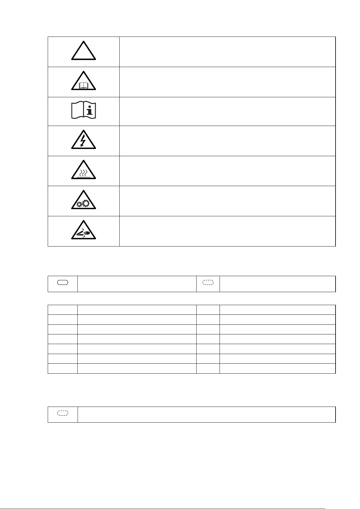
1.3 Symbols on decals
The following symbols can occur on decals on the different parts of the heat pump. Which symbols are used
depends on the heat pump model.
Installation instructions VMGFD102 – 3
Page 6
!
!
406
Warning symbols
Warning, danger!
Read the documentation provided.
Read the documentation provided.
Warning, hazardous electrical voltage!
Warning, hot surfaces!
Warning, moving parts!
Warning, risk of crushing injury!
Electrical components
Component, normal Component, accessory
3 Outdoor unit 362 Shunt valve
50 Outdoor sensor 363 Exchange valve hot water
54 Hot water sensor 365 Supply line sensor
55 Sensor hot-water top 366 Return line sensor
71 Flow sensor 406 Room sensor
304 Circulation pump 408 EVU
353 Drip tray 417 Defrost sensor
Example:
Room sensor
4 – Installation instructions VMGFD102
Page 7

Pipe connections
Bleeding
Defrosting tank
Expansion tank with safety valve, brine
Brine
Temperature and pressure relief valve
1.4 Terminology
Term Meaning
Heating system/Heat transfer fluid
circuit
Supply line The heating system’s supply line with flow direction from the heat pump to radiators/
Return line The heating system’s return line with flow direction from radiators/under floor heating
Circulation pump Circulation pump for heating system.
Refrigerant circuit The energy carrying circuit between the outdoor air and heating system.
Refrigerant The gas/liquid that circulates in the refrigerant circuit.
Tap water
Outdoor unit
Water heater
Heating system
The circuit that generates heat to the property or to the water heater.
under floor heating or water heater.
or water heater to the heat pump.
Installation instructions VMGFD102 – 5
Page 8
2 Important information
2.1
General safety precautions
Warning! Risk of personal injury! Children are not permitted to play with the product.
Caution! The heat pump must be installed by authorised installation engineers and the installation must
follow the applicable local rules and regulations as well as these installation instructions.
Caution! This product is not intended for persons (including children) with reduced physical, sensory or
psychological capacity, or who do not have knowledge or experience, unless supervised or they have
received instructions on how the apparatus functions from a safety qualified person.
Caution! When cooling it is important to limit the lowest flow line temperature to prevent condensation.
2.2 Refrigerant
2.2.1
2.2.2 Toxicity
2.2.3 Work on the refrigerant circuit
Fire risk
The refrigerant is not combustible or explosive in normal conditions.
In normal use and normal conditions the refrigerant has low toxicity. However, although the toxicity of the refrigerant is low, it can cause injury (or be highly dangerous) in abnormal circumstances or where deliberately abused.
Warning! Risk of personal injury! Spaces in which heavy vapour can collect below the level of the air must
be well ventilated.
Refrigerant vapour is heavier than air and, in enclosed spaces below the level of a door for example, and in the
event of leakage, concentrations can arise with a resultant risk of suffocation due to a lack of oxygen.
Warning! Risk of personal injury! Refrigerant exposed to a naked flame creates a poisonous irritating gas.
This gas can be detected by its odour even at concentrations below its permitted levels. Evacuate the area
until it has been sufficiently ventilated.
Caution! Work on the refrigerant circuit must only be carried out by a certified engineer!
Caution! When repairing the refrigerant circuit, the refrigerant must not be released from the heat pump it must dealt with in the appropriate way.
6 – Installation instructions VMGFD102
Page 9
Refilling must only be carried out using new refrigerant (for the amount and type of refrigerant see manufacturer’s
plate) through the service valves.
Caution! All warranties from Danfoss are void if, when filling with refrigerant other than Danfoss A/S
specified refrigerant, if there has not been written notification that the new refrigerant is an approved
replacement refrigerant together with other remedies.
2.2.4 Scrapping
Caution! When the heat pump is to be scrapped the refrigerant must be extracted for disposal. Local rules
and regulations related to the disposal of refrigerant must be followed.
2.3 Electrical connection
DANGER! Hazardous electrical voltage! The terminal blocks are live and can be highly dangerous due to
the risk of electric shock. All power supplies must be isolated before electrical installation is started. The
heat pump is connected internally at the factory, for this reason electrical installation consists mainly of
the connection of the power supply.
Warning! Electrical installation may only be carried out by an authorised electrician and must follow
applicable local and national regulations.
Warning! The electrical installation must be carried out using permanently routed cables. It must be
possible to isolate the power supply using a multi-pole circuit breaker with a minimum contact gap of 3
mm.
2.4 Water quality
Caution! A normal heating system always contains a certain amount of corrosion particulates (rust) and
sludge products from calcium oxide. This comes from acid that is naturally occurring in the fresh water
that the system is filled with. It is not good practice to have to fill the heating system regularly which is
why any leakage in the heating system should be repaired immediately. Normal filling should occur only
once or twice a year. The water in the heating system should be as clean as possible, always position the
dirt filter on the return line from the heating system to the heat pump, as close to the heat pump as
possible.
Caution! Hard water; Normally it is not a problem installing a heat pump in areas with hard water because
the normal operating temperature for the hot water does not exceed 60°C. In areas where there are
exceptional prevailing conditions with the water one can install a softening filter, which softens the water,
cleans any impurities and prevents the build up of calcification.
Installation instructions VMGFD102 – 7
Page 10

2.5 Commissioning
Caution! The installation may only be commissioned if the heating system is filled and bled. Otherwise the
circulation pump can be damaged.
Caution! If the installation is only to operate using an auxiliary heater during the installation, ensure that
the heating system is filled and bled and that the compressor cannot be started. This is carried out by
setting the operating mode to AUX. HEATER.
8 – Installation instructions VMGFD102
Page 11
3 Transport, unpacking and positioning
3.1
Transporting heat pump
Caution! The heat pump must always be transported and stored standing and in a dry environment. If the
heat pump is laid on the incorrect side it may become seriously damaged as the oil in the compressor can
run out in the pressure pipe and therefore prevent normal function.
Caution! Always secure the heat pump so that it cannot tip over during transportation.
3.2 Unpacking heat pump
3.2.1
Delivery check
1. Check that there is no transport damage.
Remove the packaging and check that the delivery contains the following components.
2.
Table 1. Supplied contents
Quantity Name
1 Heat pump
1 Control unit
1 Document set
1 Package (1 x shut-off valve with filter, 1 x outdoor sensor)
3.3 Positioning the heat pump
3.3.1
Recommended location
When positioning the heat pump, note the following:
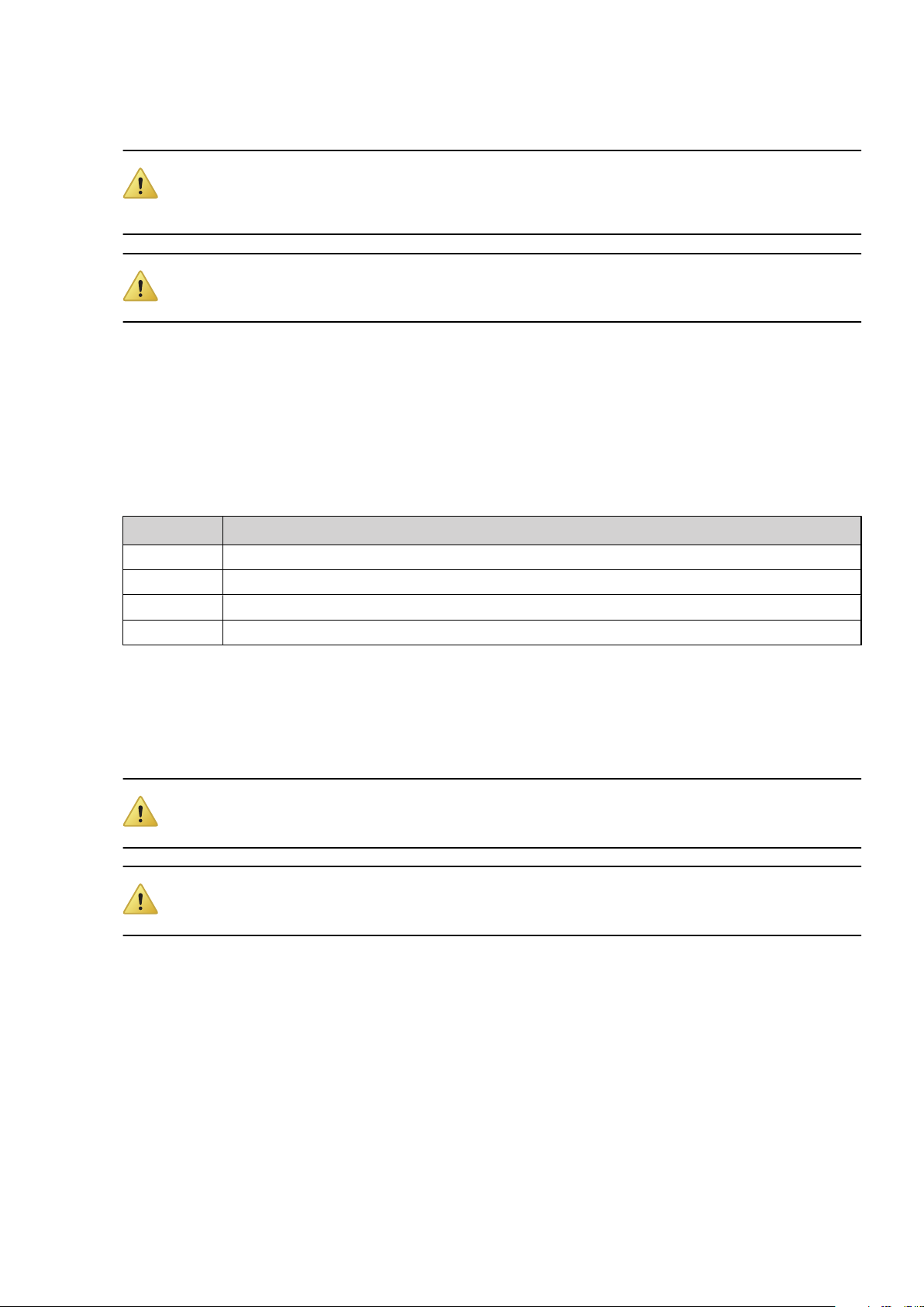
Caution! The heat pump must be positioned outdoors on a stable base. The floor must be able to support
the gross weight of the heat pump. (see Technical data)
Caution! The heat pump must be secured on a stable base, for example a cast foundation. All four
mounting points must be secured to the base.
Installation instructions VMGFD102 – 9
Page 12
100 mm
~900 mm
b
c
a
7
5
4
3
6
1
8
2
Position Description
a Drainage hole
b Foundation
c Gravel
Meas-
6-9 kW 11-13 kW 16-18 kW
urements
1 450 mm 470 mm 710 mm
2 424 mm 480 mm 480 mm
3 618 mm 672 mm 857 mm
4 130 mm 190 mm 145 mm
5 61 mm 65 mm 65 mm
6 ~1,000 mm ~1,200 mm ~1300 mm
7 ~650 mm ~720 mm ~720 mm
8 Ø 65 mm Ø 65 mm Ø 65 mm
Bolt size
6-9 kW 11-13 kW 16-18 kW
M10 (4x) M12 (4x) M12 (4x)
10 – Installation instructions VMGFD102
Page 13
Caution! A driptray is installed with the purpose of gathering and draining away melt water during
defrosting. Connect a hose or pipe along with a heat trace cable between the outlet of the drip tray and a
drain or a free draining piece of ground. The heat cable must be connected to the terminal provided and
is necessary to prevent ice blockage.
Caution! Check with a spirit level that the heat pump is installed horizontally.
Caution! Incorrect positioning of the heat pump risks reduction of performance.
Caution! The unit with water heater must be placed indoors, in an area with a floor drain.
Caution! The unit with water heater must be placed indoors, on a stable surface. The floor must be able to
support the gross weight of the unit with filled water tank (see Technical data).
Note! Avoid placing the heat pump near windows or walls to noise sensitive areas.
Note! Ensure that there is sufficient distance to neighbouring properties so that they are not exposed to
noise. Applicable local regulations must be followed.
Note! The heat pump should not be enclosed.
Note! Keep the heat pump and its immediate area free of snow, ice, leaves etc.
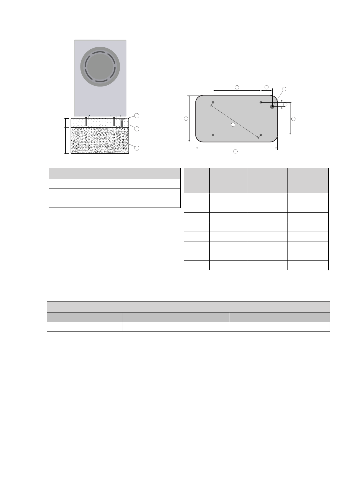
Note! Remember that the heat pump must have a certain amount of space in order to function and for
servicing. Otherwise there is a risk that the air will recirculate from exhaust to intake. Avoid this by
following the dimensions given below.
Installation instructions VMGFD102 – 11
Page 14
>
2
0
0
0
m
m
>
2
0
0
0
m
m
>1500
m
m
>
300
m
m
>
2
000
mm
1
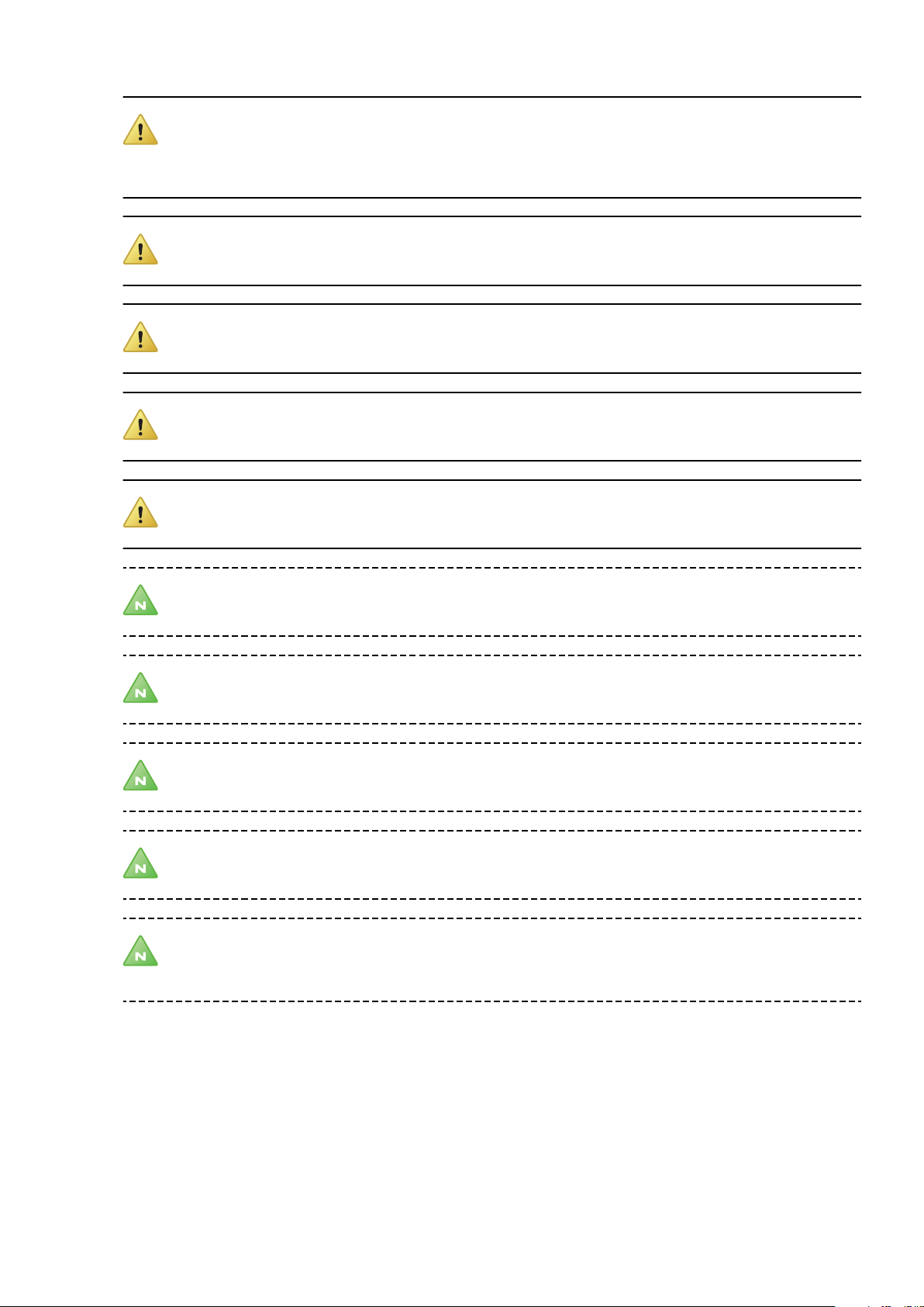
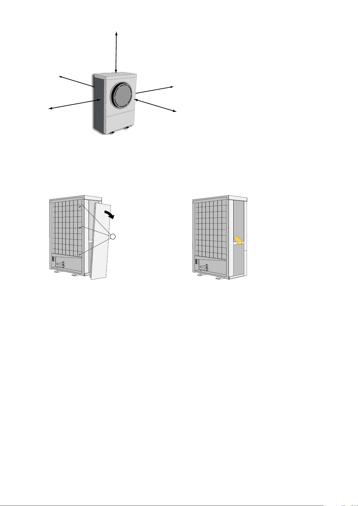
3.3.2 Lifting instructions
To lift the heat pump into position, unscrew the side plates by slackening off the screws (1).
Then use the side members behind the side panels to lift and position the heat pump.
12 – Installation instructions VMGFD102
Page 15
33
5
4
6
1
2
600
380
204
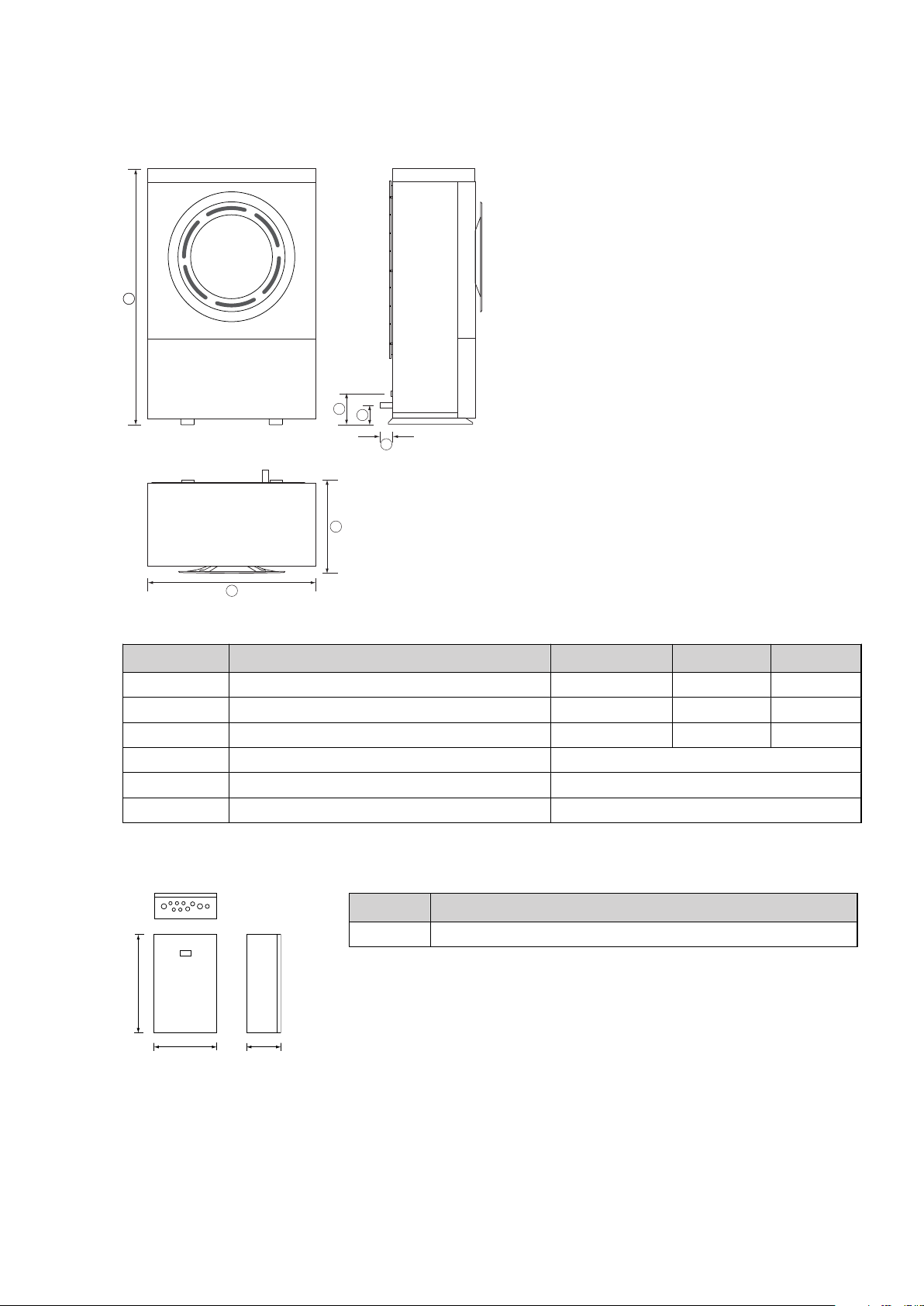
1
4 The heat pump
4.1
Dimensions and connections
Position Description 6-9 kW 11-13 kW 16-18 kW
1 Width 856 mm 1,016 mm 1,166 mm
2 Depth 510 mm 564 mm 570 mm
3 Height 1,272 mm 1,477 mm 1,557 mm
4 Height to supply line pipe, 28 mm Cu 155.5 mm
5 Height to return line pipe, 28 mm Cu 96.5 mm
6 Length max protruding pipe 30 mm
Control unit DHP-AQ Mini
Position Description
1 Lead-in for supply, sensor and communication cables
Control unit DHP-AQ Midi
Installation instructions VMGFD102 – 13
Page 16
675
420
255
1
2
3
4
1845 ±10
596
455
690
1
2
3
4
5
125
210
330
6
7
8
9
10
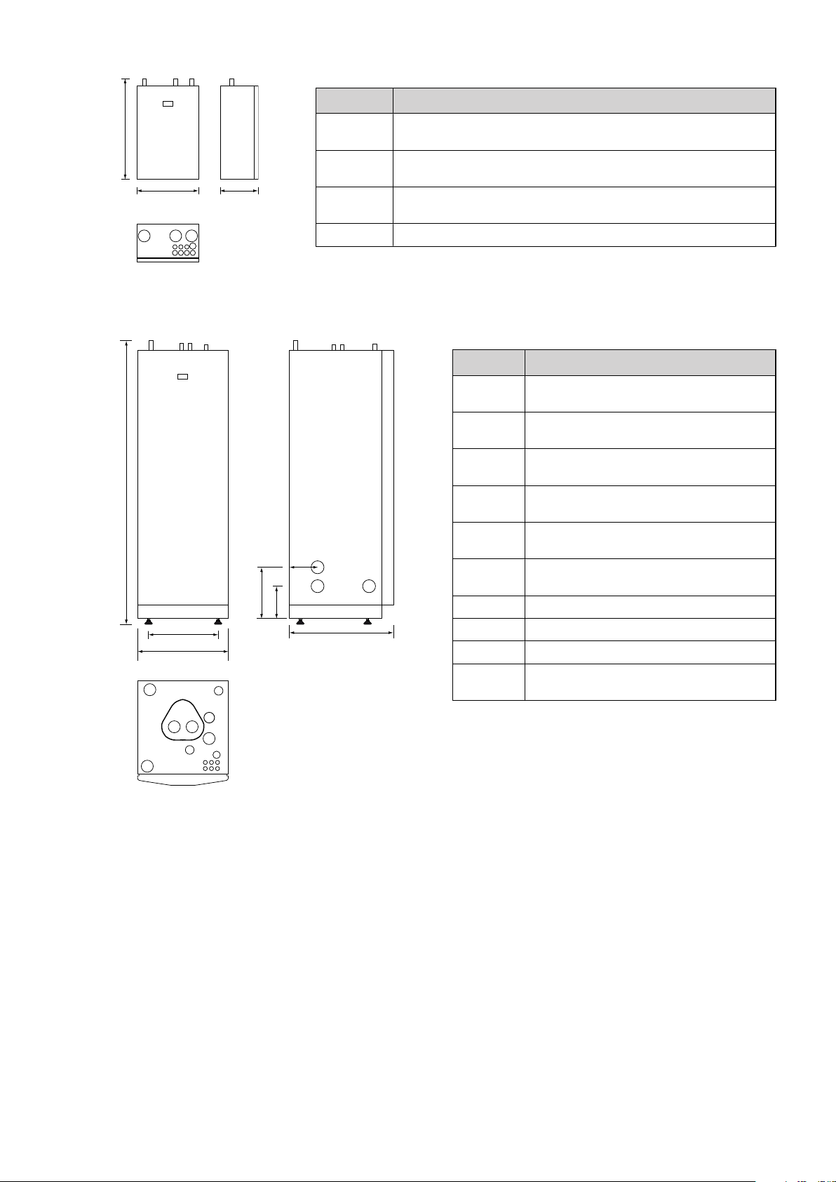
Control unitDHP-AQ Maxi
Position Description
1 Supply line for heating system,
28 mm Cu
2 Supply line to water heater,
28 mm Cu
3 Supply line from heat pump,
28 mm Cu
4 Lead-in for supply, sensor and communication cables
Position Description
1 Supply line heating system,
28 mm Cu
2 Return line heating system,
28 mm Cu
3 Connection for bleed valve,
22 mm Cu
4 Hot water line,
22 mm Cu
5 Cold water line,
22 mm Cu
6 Lead-in for supply, sensor and communica-
tion cables
7 Supply or return line heat pump
8 Supply or return line heat pump
9 Extra knock-out
10 Safety valve for temperature and pressure
(only applies to certain models)
14 – Installation instructions VMGFD102
Position 7 and 8 can be connected to either the left or righthand side or bottom of the control unit.
Page 17
11
10
12
13
14
16
15
17
1
2
3
4
5
6
7
8
9
19
18
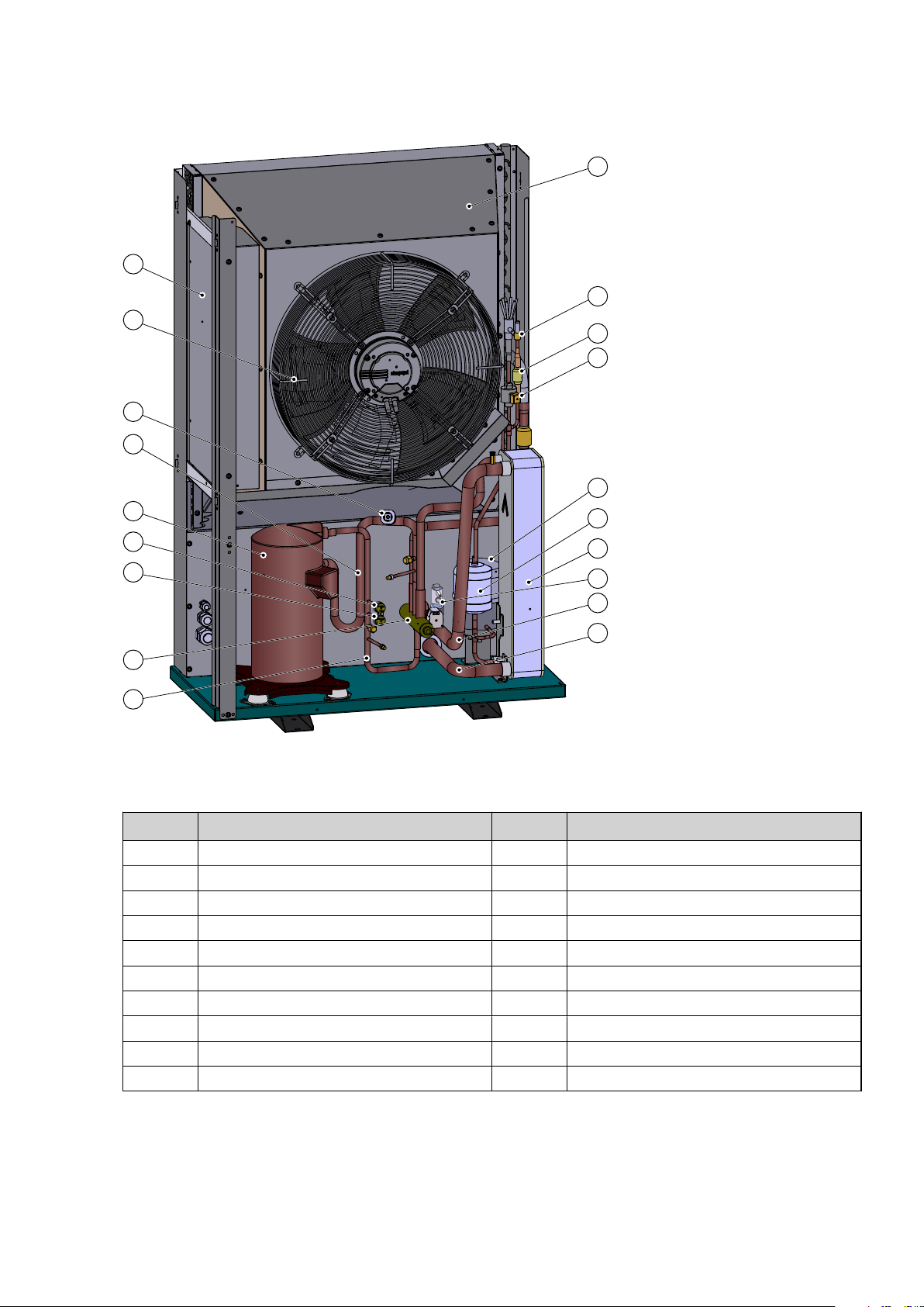
4.2 Components
4.2.1
Outdoor unit
Position Name Position Name
1 Electrical cabinet 11 Electronic expansion valve
2 Fan 12 Receiver
3 Pressure transmitter 13 Drying filter
4 Suction line 14 Heat exchanger
5 Compressor 15 Flow sensor
6 High pressure switch 16 Heating system supply line
7 Operating pressure switch 17 Return line heating system
8 Four-way valve 18 Solenoid
9 Discharge pipe 19 Non-return valve
10 Air heat exchanger
Installation instructions VMGFD102 – 15
Page 18
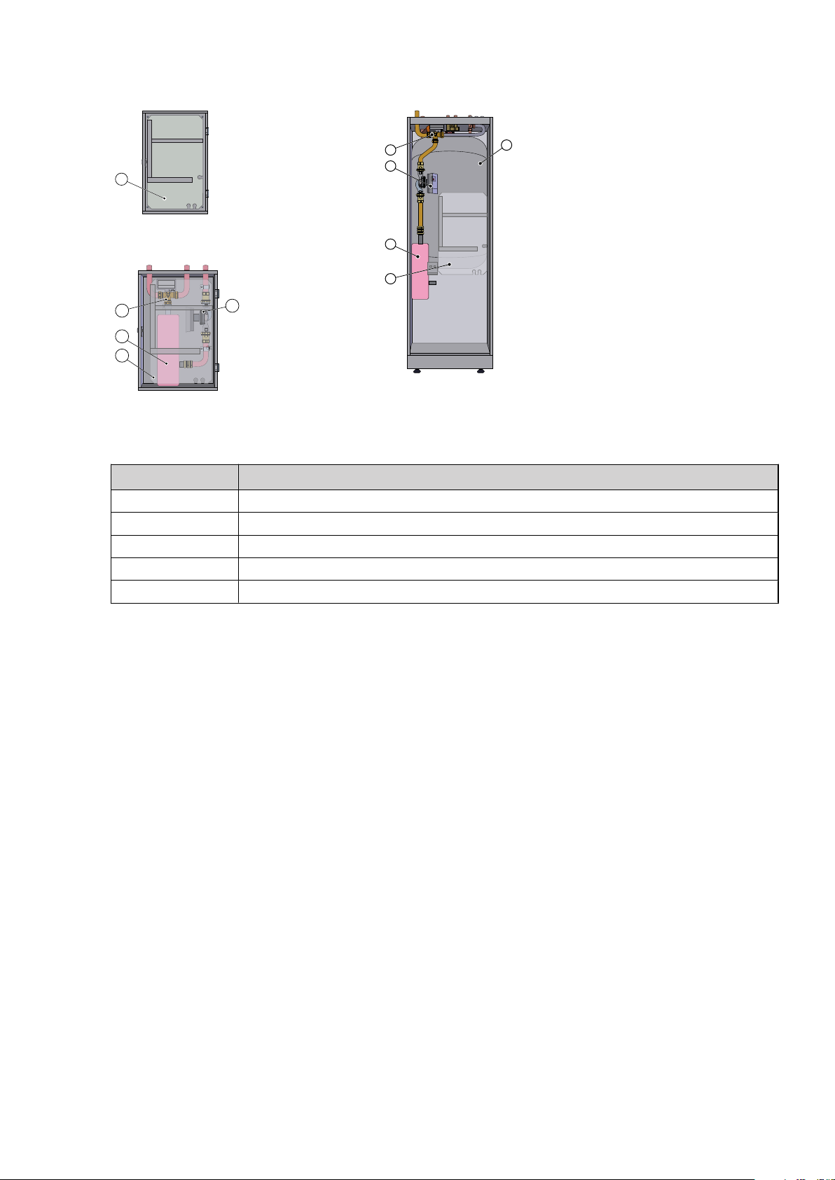
4.2.2 Indoor unit
1
1
2
4
3
5
1
2
3
4
DHP-AQ Mini
DHP-AQ Midi
DHP-AQ Maxi
Position Description
1 Control module (transparent in image)
2 Immersion heater
3 Reversing valve
4 Circulation pump
5 Water heater
4.2.3 Speed controlled fan
The fan is operated by a permanent solenoid motor with great efficiency. The fan starts at a nominal speed, which
differs depending on the size of output. The fan speed is adjusted up or down as required which is determined by
the temperatures in the refrigerant circuit.
4.2.4 Electronic expansion valve
When the refrigerant passes the expansion valve the pressure and temperature of the refrigerant are reduced. In
this way the energy in the outdoor air is available to the refrigerant circuit. By regulating the opening degree of
the expansion valve one can optimise the flow in the refrigerant circuit in different operating conditions. Control
of the electronic expansion valve is based on the measurements of temperatures and pressures in the refrigerant
circuit and outside air.
4.2.5 Auxiliary heat
An auxiliary heater is included in DHP-AQ Midi and DHP-AQ Maxi and consists of an immersion heater, which is
located on the supply line ahead of the reversing valve. An immersion heater is available for DHP-AQ Mini as an
accessory. Also see System solution, Page 24, pos 114.
Immersion heaters in the DHP-AQ series intended for 400V supply voltage have three heating elements and can be
controlled in five power stages. Products for 230V have two heating elements and are controlled in three power
stages.
The parameter MAX STEP determines the number of power stages the immersion heater can be controlled to. The
two stages 4 and 5 cannot be engaged when the compressor is in operation as opposed to stages +4 and +5
where it is possible.
With an internal immersion heater which is controlled by several power stages an external auxiliary heater, for
example an electric boiler, can be controlled using the potential free output 101.8 – 101.16.
If an immersion heater of a different type is used that requires a start signal in DHP-AQ Mini (placed before the hot
water reversing valve) the auxiliary heater is controlled from the potential free output 101.8 – 101.16. The parameter MAX STEP is set to ”P”.
16 – Installation instructions VMGFD102
Page 19
In the event of power cuts longer than three minutes, only a 6 kW output will be connected immediately after
power has returned, the remaining output is delayed two hours.
4.2.6 Compressor heater
The compressor heater runs in intervals when the outdoor temperature falls below 10°C. The compressor heater
does not run at the same time as the compressor.
4.3 Principle description
A heat pump utilises the renewable energy from the sun and that is also found in a natural heat source, such as
rock, ground, lakes, ground water or air. The heat pump can be compared to a reversed refrigerator; in a refrigerator heat is transferred from the inside of the refrigerator to the outside, whereas in a heat pump, the solar energy
that is stored in a heat source is transferred to the inside of the house. In both a refrigerator and heat pump the
process is driven by an electrically powered compressor. The heat pump uses the solar energy in the heat source
and gives off two to three times more heat energy than it uses in electrical energy. The heat pump is, therefore, a
very environmentally friendly and economical way of heating a house.
4.4 Heating
The heat pump produces heating (see figure below).
When the compressor (1) receives a start signal the refrigerant is compressed in gas form via the 4 way valve (5) to
the plate heat exchanger (7). The hot refrigerant gives off heat through the plate heat exchanger (7) to the heating
system (8) and transfers to liquid phase. The refrigerant continues through the drying filter (10) and the electronic
expansion valve (11) to the air exchanger (15). In the air exchanger (15) the refrigerant is heated to gas form by the
hotter outdoor air. The gas continues via the 4 way valve (5) back to the compressor (1).
Installation instructions VMGFD102 – 17
Page 20
3
2
1
1918
17
15
14
16
11
13
12
10
9
8
7 6
5
4
Position Description Position Description
1 Compressor 11 Electronic expansion valve
2 Operating pressure switch 12 Non-return valve
3 High pressure switch 13 Solenoid
4 Discharge pipe sensor 14 Refrigerant sensor 2
5 Four-way valve 15 Air exchanger (evaporator)
6 Heating system (cold return line) 16 Fan
7 Plate heat exchanger (condenser) 17 Refrigerant sensor 1
8 Heating system ( hot supply line) 18 Pressure transmitter
9 Receiver 19 Temperature transmitter
10 Drying filter
The heat pump can produce heat for heating (house, pool), hot water and cooling. The hot water requirement is
prioritised before the heating requirement and cooling requirement. The heating requirement is calculated from
outdoor temperature and set heat curve.
For a fuller description of heat curves etc., seeImportant parameters, Page 39.
4.5 Hot water function
The water heater is equipped with a TWS coil (Tap Water Stratificator). The hot water is led from the heat pump
through the water heater in the TWS coil from the top down. In this way the upper section of the water heater,
where the hot water is tapped from, is always heated first.
Heating the hot water in the water heater is not stopped by the temperature but via the pressure in the refrigerant
circuit of the heat pump unit. The operating pressure switch on the pressure pipe breaks at 28.5 bar. This means
that heat pumps in different output classes may have slightly different peak temperatures for hot water. As a rule
the peak temperature is between 54 – 58°C in a 180-litre water heater. Thanks to the design of the water heater
and the TWS coil the hot water layers itself so that the hottest water is always at the top of the water heater and
the cooler water at the bottom.
Two sensors indicate the present temperature of the hot water to the heat pump controls. A top water sensor that
is located in the top of the water heater, and a hot water sensor located approx 50 cm up from the bottom of the
water heater. Both the sensor values are ”weighted” where the hot water sensor influence is 65 % (factory setting,
18 – Installation instructions VMGFD102
Page 21
3
2
1
1918
17
15
14
16
11
13
12
10
9
8
7 6
5
4
can be changed if necessary). This means that if the start value for hot water production is set to 40°C the heat
pump need not necessarily start hot water production when the hot water sensor displays 40°C but also makes
reference to what temperature the peak water sensor displays. If it is still very hot at the top of the water heater
the start of hot water production will be delayed.
With anti-legionella operation, when the immersion heater heats the water heater to 60°C to prevent growth of
legionella bacteria, the peak water sensor temperature has no impact, only the hot water sensor has control. Antilegionella is factory set as top heating interval every 7th day.
4.6 Defrost function
The heat pump defrosts (see figure below).
Note! The designations for condenser and evaporator are switched during the defrost function (like the
cooling function) compared to the heating function, because the designations follow the cooling
technical function that respective units have (evaporation respectively condensing).
When the compressor (1) receives a start signal the refrigerant is compressed in gas form via the 4 way valve (5) to
the air exchanger (15). The hot refrigerant gives off heat to the air exchanger (15), shifts to liquid phase and continues to the plate heat exchanger (7). In the plate heat exchanger (7) the refrigerant is heated to gas form by the
hotter heating system (6). The heating system is cooled. The refrigerant continues via the 4 way valve (5) back to
the compressor (1).
Position Description Position Description
1 Compressor 11 Electronic expansion valve
2 Operating pressure switch 12 Non-return valve
3 High pressure switch 13 Solenoid
4 Discharge pipe sensor 14 Refrigerant sensor 2
5 Four-way valve 15 Air exchanger (condenser)
6 Heating system (hot return line) 16 Fan
7 Plate heat exchanger (evaporator) 17 Refrigerant sensor 1
8 Heating system ( cold supply line) 18 Pressure transmitter
Installation instructions VMGFD102 – 19
Page 22

3
2
1
1918
17
15
14
16
11
13
12
10
9
8
7 6
5
4
Position Description Position Description
9 Receiver 19 Temperature transmitter
10 Drying filter
Defrosting is initiated by low temperature in the refrigerant circuit after the air exchanger and, among other
things, is dependent on outdoor temperature, humidity and operating time. The length of defrosting varies
depending on the extent of freezing of the air exchanger. Defrost continues until the air heat exchanger is free of
ice and the temperature after the air exchanger has risen to the desired temperature. After completed defrosting
the heat pump returns to the operating mode before defrosting.
During defrosting the heat pump retrieves energy from the house's heating system. The water volume in the heating system can be increased by installing a buffer tank. The buffer tank can also act as a surge tank.
4.7 Cooling function
The heat pump produces cooling (see figure below).
The refrigerant process is similar to that at the defrosting function.
Note! The designations for condenser and evaporator are switched during the cooling function (like the
defrosting function) compared to the heating function, because the designations follow the cooling
technical function that respective units have (evaporation respectively condensing).
When the compressor (1) receives a start signal the refrigerant is compressed in gas form via the 4 way valve (5) to
the air exchanger (15). The hot refrigerant gives off heat to the air exchanger (15), shifts to liquid phase and continues to the plate heat exchanger (7). In the plate heat exchanger (7) the refrigerant is heated to gas form by the
hotter heating system (6). The heating system is cooled. The refrigerant continues via the 4 way valve (5) back to
the compressor (1).
Position Description Position Description
1 Compressor 11 Electronic expansion valve
2 Operating pressure switch 12 Non-return valve
3 High pressure switch 13 Solenoid
20 – Installation instructions VMGFD102
Page 23
1
3
6
5
7
8
4
9
2
10
Position Description Position Description
4 Discharge pipe sensor 14 Refrigerant sensor 2
5 Four-way valve 15 Air exchanger (condenser)
6 Heating system (hot return line) 16 Fan
7 Plate heat exchanger (evaporator) 17 Refrigerant sensor 1
8 Heating system ( cold supply line) 18 Pressure transmitter
9 Receiver 19 Temperature transmitter
10 Drying filter
Cooling function is started by the heat pump control unit and is primarily temperature controlled. If the hot water
heater is installed the control unit will alternate between cooling and hot water production with prioritisation for
the hot water requirement.
4.8 Check and safety functions
The heat pump has a number of check and safety functions to protect the installation against damage during
abnormal operating conditions.
The diagram below shows the heat pump's circuits with respective safety functions.
Symbol explanation
1 Heat transfer fluid circuit
2 Flow sensor
3 Safety valve, heat transfer fluid circuit, externally mounted
4 Refrigerant circuit
5 Operating pressure switch
6 High pressure switch
7 Pressure transmitter
8 Compressor
9 Fan
10 Discharge pipe sensor
Heat transfer fluid circuit (1)
If the flow in the heat transfer fluid circuit is below the permitted value at heat pump start and before the defrosting blocks the flow sensor (2) heat pump's normal operation, an alarm indicator on the control unit control panel
flashes and a warning text appears in the display of the control panel. The alarm resets itself when the flow
returns.
If the pressure in this circuit exceeds the opening pressure for the safety valve (3), the valve opens, releases the
overpressure and closes again. The safety valve overflow pipe must have an open connection to the drain and
visibly flow into this in a frost-free environment.
Refrigerant circuit (4)
The refrigerant circuit's high pressure side is equipped with a high pressure switch (6) and an operating pressure
switch (5).The operating pressure switch stops the compressor when the operating pressure is reached.
If the operating pressure switch does not work and the pressure continues to increase in the circuit, the high pressure switch activates when its break pressure is reached, whereupon the compressor stops and the heat pump's
normal operation is blocked.
If the high pressure switch is activated an alarm indicator flashes on the control unit's control panel and a warning
text appears in the display of the control panel. The blocked heat pump is reset by setting the operating mode to
OFF and then back to the previously selected mode.
Installation instructions VMGFD102 – 21
Page 24

If the pressure transmitter (7) registers too low pressure in the refrigerant circuit, the heat pump's normal operation is blocked, an alarm indicator on the heat pump's control panel flashes and a warning text appears in the
display of the control panel. The blocked heat pump is reset by setting the operating mode to OFF and then back
to the previously selected mode. The pressure transmitter is also used to monitor temperature and pressure at
compressor start. Deviations are handled in the same way as low pressure.
Compressor (8)
The compressor is equipped with a thermal over current relay to protect the compressor against over current.
If the over current relay (see figure below) is activated, the heat pump's normal operation is blocked, an alarm
indicator on the control unit's control panel flashes and a warning text appears in the display of the control panel.
The blocked heat pump is reset by setting the operating mode to OFF and then back to the previously selected
mode.
The compressor is also equipped with an internal protector that stops the compressor if it risks becoming overhea-
ted. The internal protector cannot be reset manually, the compressor must cool before it can be restarted. No
alarm connected to this protector.
The discharge pipe sensor (10) stops the compressor at too high pressurised gas temperature. This is indicated in
the display by a square. The stop is ceased when the temperature becomes normal.
Fan (9)
The fan motor is equipped with motor protection. If this is activated, the heat pump's normal operation is blocked,
an alarm indicator on the control unit's control panel flashes and a warning text appears in the display of the control panel.
Alarms can be caused by objects sticking in the fan or the fan having frozen solid. Rectify the cause of the alarm
and reset the heat pump by setting the operating mode to OFF and then back to the previously selected mode.
Speed (rpm) controlled circulation pump
The circulation pump has an internal overload protector, which is reset automatically after cooling.
The overload protector also activates the alarm for the circulation pump and blocks the heat pump's normal oper-
ation. Indication occurs by the alarm indicator flashing on the control unit's control panel and a warning text
appears in the display of the control panel. The circulation pump will attempt to start for 45 seconds every 5
minutes to try to acknowledge the alarm automatically. If the function is not normal after 5 start attempts the heat
pump is constantly blocked and must be reset by setting the operating mode to OFF and then back to the previously selected mode.
Alarm mode
If an alarm that affects the heat pump's normal operation is activated this will be indicated in the control panel's
display window. In order to further attract attention, the heat pump will not produce hot water.
The heat pump will initially try to meet the heat demand using the compressor. If this is not possible, the built-in
electric heating element engages.
Immersion heater
The auxiliary heater consists of an electric heating element mounted on the heating system supply line. It has an
overheat protector that switches off the electric heating element if it is at risk of becoming overheated. The overheat protector's control panel is located in the control unit (see the image below).
If the overheat protector is activated an alarm indicator flashes on the heat pump's control panel and a warning
text appears.
The overheat protector is reset by pushing the reset button, which is on the overheat protector.
Electrical system
22 – Installation instructions VMGFD102
Page 25

4
1
2
3
2
3
2
A
B C D
The heat pump control and control unit are fused with fuses F1 and F2 (see figures below).
Symbol explanation
A Heat pump
B Control unit DHP-AQ Mini
C Control unit DHP-AQ Midi
D Control unit DHP-AQ Maxi
1 Fuse F1
2 Fuse F2
3 Overheating protection
4 Overcurrent protection
Installation instructions VMGFD102 – 23
Page 26

5
71
96
91
52
114
100
36
51
50
40
112
80
62
21
80
63
64
33
10
11
10
11
5 System solution
Explanations for the positions are given after the images of the system solution.
5.1 System solution DHP-AQ Mini
DHP-AQ Mini includes the control module with supply and return line sensors. The heat pump produces only heat
or cooling. Two heating circuits can be connected, one using a shunt. The shunt is controlled by the heat pump
control system. The flow line temperature is controlled with reference to the outside temperature following a set
heat curve. The additional heater starts automatically on demand.
Buffer tank is installed for equalisation of the temperature for the heating system and to guarantee sufficient
energy when defrosting. The buffer tank volume must be 20 l/kW heat pump output (for systems without water
heaters). DHP-AQ Mini does not contain a water heater. Water heater is available as an accessory for DHP-AQ Midi
and is included in DHP-AQ Maxi.
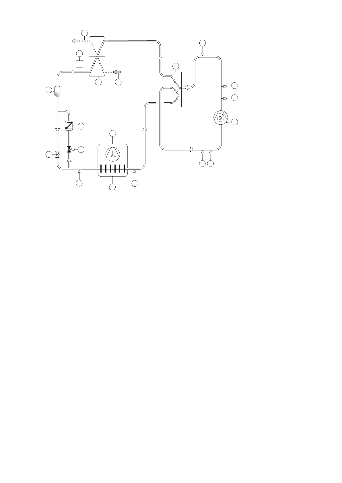
5.2 System solution DHP-AQ Midi
DHP-AQ Midi includes the control module with supply and return pipe sensors, circulation pump, 3-way valve and
electric auxiliary heater. The heat pump produces heat, cooling and hot water. Production of heating and hot
water cannot occur at the same time because the exchange valve for heating and hot water is positioned after the
heat pump and the auxiliary heater. Hot water production is prioritised ahead of heat and cooling. Two heating
circuits can be connected, one using a shunt. The shunt is controlled by the heat pump control system. The flow
line temperature is controlled with reference to the outside temperature following a set heat curve. The additional
24 – Installation instructions VMGFD102
Page 27

91
52
114
100
36
51
50
112
80
62
21
80
63
64
33
10
11
10
11
53
55
77
85
87
83 80
13
12
18
40
5
71
96
heater starts automatically on demand. The auxiliary heater carries out peak heating charging (anti-legionella
function) in those operating modes that permit auxiliary heat.
Buffer tank is installed for equalisation of the temperature for the heating system and to guarantee sufficient
energy when defrosting. The buffer tank volume must be 10 l/kW heat pump output (for systems with water heaters). Water heater is available as an accessory.
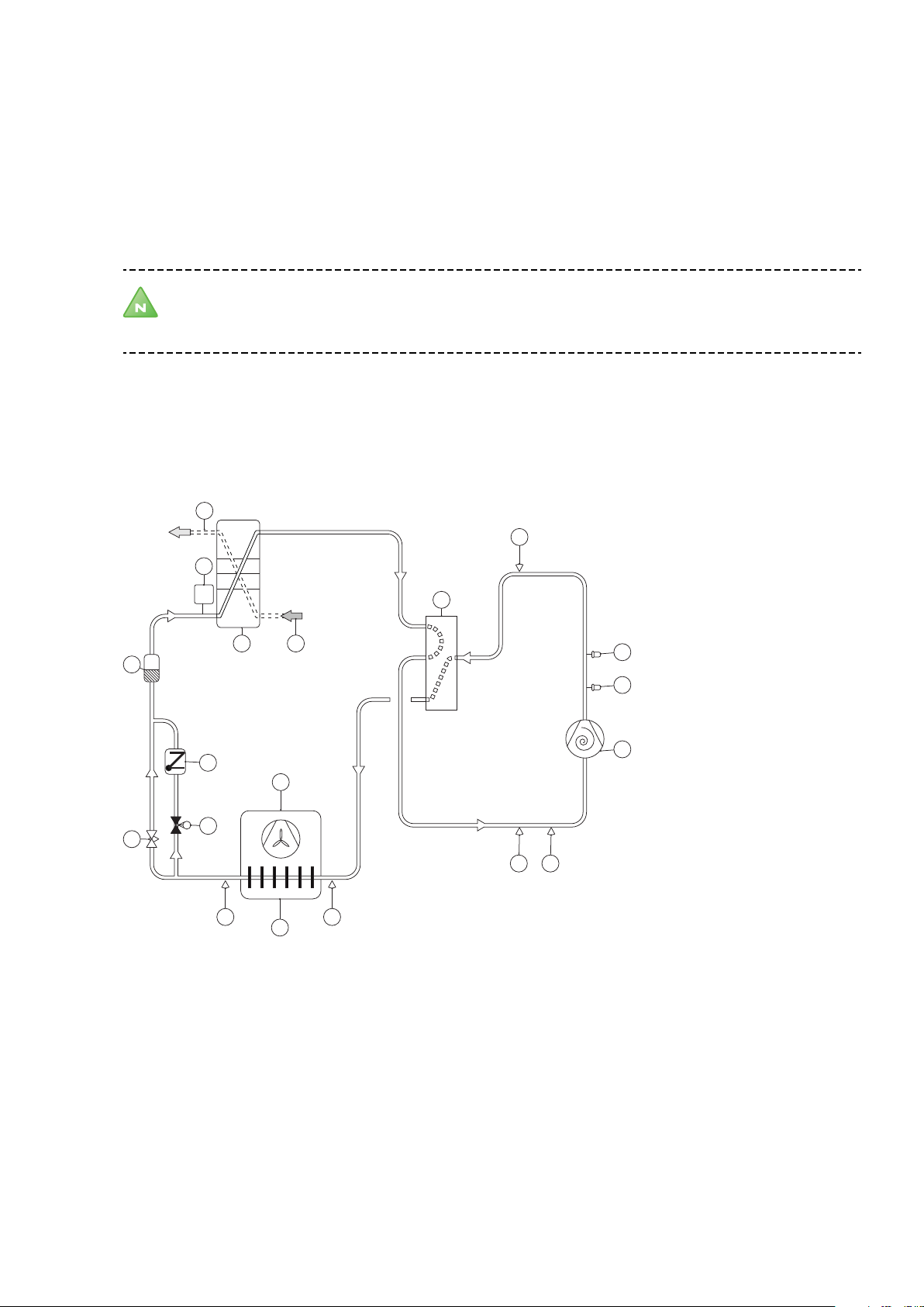
5.3 System solution DHP-AQ Maxi
DHP-AQ Maxi includes the control module with supply and return pipe sensors, circulation pump, 3-way valve,
electric auxiliary heater and water heater. The heat pump produces heat, cooling and hot water. Production of
heating and hot water cannot occur at the same time because the exchange valve for heating and hot water is
positioned after the heat pump and the auxiliary heater. Hot water production is prioritised ahead of heat and
trol system. The flow line temperature is controlled with reference to the outside temperature following a set heat
curve. The additional heater starts automatically on demand. The auxiliary heater carries out peak heating charg-
cooling. Two heating circuits can be connected, one using a shunt. The shunt is controlled by the heat pump con-
ing (anti-legionella function) in those operating modes that permit auxiliary heat.
Buffer tank is installed for equalisation of the temperature for the heating system and to guarantee sufficient
energy when defrosting. The buffer tank volume must be 10 l/kW heat pump output (for systems with water heaters).
Installation instructions VMGFD102 – 25
Page 28

5
71
96
91
52
114
100
36
51
50
40
112
80
62
21
80
63
64
33
10
11
10
11
53
55
77
87
83 80
13
12
18
Position Name Position Name
5 Heat pump unit 62 Room sensor
10 Supply line 63 Shunt valve
11 Return line 64 Supply line sensor shunt group
12 Cold water 71 Flow sensor
13 Hot water 77 Switching valve for hot water
18 Water heater 80 Shut-off valve
33 Circulation pump shunt group 85 Bleed valve
21 Buffer tank 83 Non-return valve
36 Circulation pump 87 Safety valve (9 bar)
40 Control unit 91 Strainer
50 Outdoor sensor 96 Flexible hose
51 Supply line sensor 100 Safety valve (1.5 bar)
52 Return line sensor 112 Expansion vessel, closed
26 – Installation instructions VMGFD102
Page 29

Position Name Position Name
53 Hot water sensor 114 Auxiliary heat
55 Peak temperature sensor
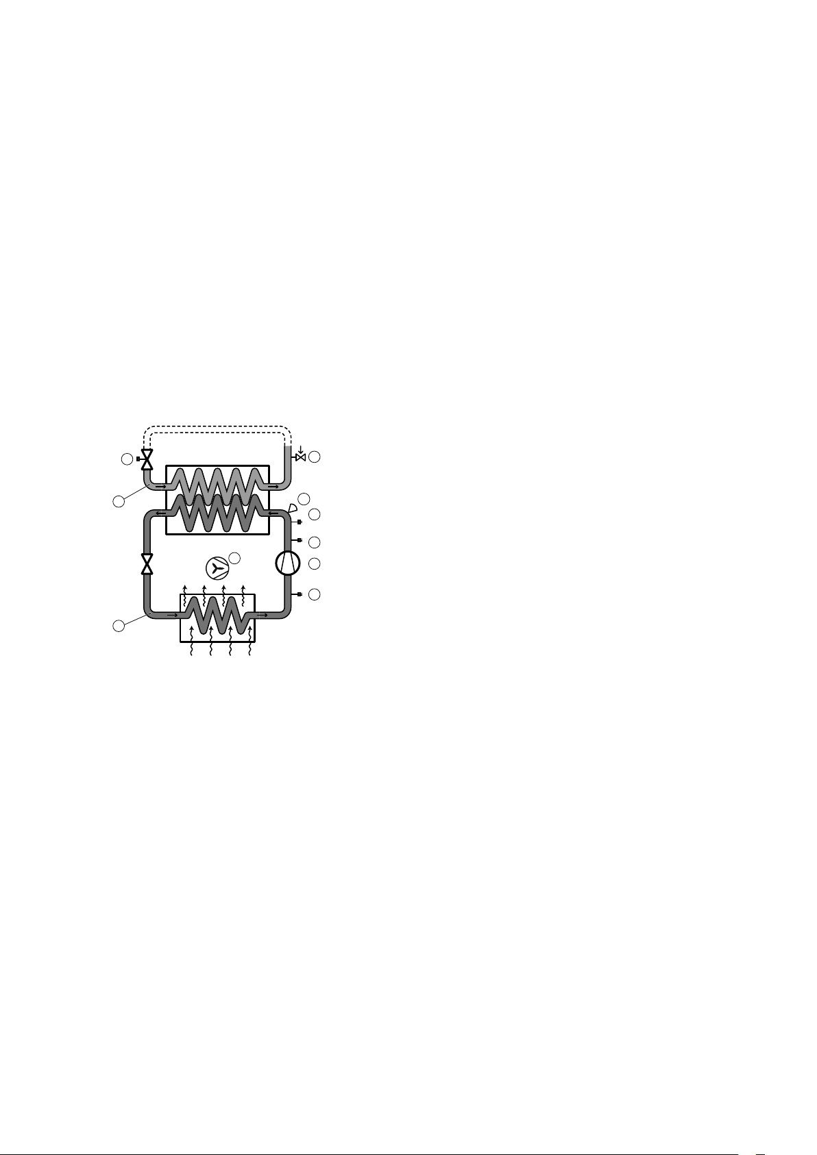
5.4 System solution intermediate exchanger
To safeguard against the pipes freezing an intermediate exchanger can be installed indoors. In such cases one
must use glycol intended for refrigerant applications in the circuit to the heat pump unit and an extra circulation
pump. Follow the supplier's instructions for mixing, but if none is given 35% is the lowest concentration recommended. To order and for more information about the intermediate exchanger and the circulation pump, contact
Danfoss.
Caution! No glycol mixtures may be used in systems with hot zinc dipped pipes or components.
Installation instructions VMGFD102 – 27
Page 30

5
71
96
100
112
82 38
65
Position Name Position Name
5 Heat pump unit 82 Adjustment valve
38 Circulation pump 96 Flexible hose
65 Intermediate exchanger 100 Safety valve (1.5 bar)
71 Flow sensor 112 Expansion vessel, closed
28 – Installation instructions VMGFD102
Page 31

6 Piping installation
6.1
Pipe connection
Caution! Piping installation must be carried out in accordance with applicable local rules and regulations.
The hot water tank must be equipped with an approved safety valve.
Caution! There is a risk of the pipes to the heat pump freezing when water circulation through the heat
pump stops when outdoor temperatures fall below freezing. Normally the integrated flow sensor gives an
alarm if there is low flow (assumes that there is current to the heat pump), for example when the radiator
pump has stopped. In the event of longer flow stops, for example in case of power failure or if the plant is
OFF, there is however an obvious risk of freezing . By installing a stop cock on the inside of the house wall
it is possible to drain the part of the system that goes out to the heat pump if necessary. Another way of
ensuring against freezing is to install an intermediate exchanger indoors. In such cases one must use
glycol intended for refrigerant applications in the circuit to the heat pump unit and an extra circulation
pump, see System solution intermediate exchanger. Another option is to fill the heating system with antifreeze.
Caution! To prevent leaks, ensure that there are no stresses in the connecting pipes!
Caution! It is important that the heating system is bled after installation. Bleed valves must be installed
where necessary.
Caution! Heating systems with closed expansion tanks must also be supplied with approved pressure
gauges and safety valves.
Caution! Cold and hot water pipes and overflow pipes from safety valves must be made of heat resistant
and corrosion-resistant material, e.g. copper. The safety valve overflow pipes must have an open
connection to the drain and visibly flow into this in a frost-free environment.
Caution! The connecting pipe between the expansion tank and the safety valve must slope continuously
upwards. A continuous upwards slope means that the pipe must not slope downwards from the
horizontal at any point.
Note! Ensure that the pipe installation is carried out in accordance with the dimensions and connection
diagrams.
6.2 Connecting cold and hot water lines
If necessary, connect the cold water and hot water pipes with all the necessary components, see System solution,
Page 24.
6.3 Connecting the heating system supply and return lines
Connecting the heating system supply and return lines, see System solution, Page 24.
For information on how flexible hoses should be installed, see Flexible hoses, Page 30.
Installation instructions VMGFD102 – 29
Page 32

1
2
1. Connect the supply pipe with a flexible hose connection and with all the necessary components.
2.
Connect the return pipe with a flexible hose connection and with all the necessary components including a
filter.
3. Insulate the supply and return lines all the way to the heat pump.
Position Description
1 Supply line 28 mm copper pipe
2 Return line 28 mm copper pipe
6.4 Noise and vibrations
6.4.1 Installation of the heat pump
To prevent disturbing noise from the heat pump the following recommendations should be observed:
In the event the heat pump is positioned on a vibration sensitive base, vibration dampers should be used. The
•
vibration dampers must be correctly dimensioned with regard to the heat pump's weight so that static spring
depression of at least 2 mm is obtained in all mounting components. Vibration dampers are available to purchase as accessories.
Connection of the heat transfer fluid to the heat pump must be made using a flexible hose to prevent trans-
•
mission of vibration to building construction and the pipe system, see Flexible hoses, Page 30.
Ensure that pipes at lead-ins are not lying against the walls.
•
Ensure that the electrical supply cable does not provide a path for vibration because it is overstretched.
•
6.4.2 Flexible hoses
All pipes should be routed in such a way that vibrations cannot be transmitted from the heat pump through the
piping and out into the building. This also applies to the expansion pipe. We recommend that flexible hoses are
30 – Installation instructions VMGFD102
Page 33

used for all pipe connections to avoid the transmission of vibrations. Flexible hoses are available to purchase as
accessories. The figures below show how appropriate and inappropriate installations look using this type of hose.
Installation instructions VMGFD102 – 31
Page 34

4
3
1
5
6
3
4
5
6
2
1
7
7 Electrical Installation
DANGER! Hazardous electrical voltage! The terminal blocks are live and can be highly dangerous due to
the risk of electric shock. All power supplies must be isolated before electrical installation is started. The
heat pump is connected internally at the factory, for this reason electrical installation consists mainly of
the connection of the power supply.
Warning! Electrical installation may only be carried out by an authorised electrician and must follow
applicable local and national regulations.
Warning! The electrical installation must be carried out using permanently routed cables. It must be
possible to isolate the power supply using a multi-pole circuit breaker with a minimum contact gap of 3
mm.
7.1 Control centre
7.1.1
Installation
Caution! The control centre must be installed in a frost-free environment.
The control centre contains the necessary components for voltage supply, control systems and operation.
7.1.2 DHP-AQ Mini electrical components in the control centre
Symbol explanation
1 Terminal block
3 Hub card
4 Space for expansion card (accessory)
5 Space for communications card (accessory)
6 Space for terminal block for expansion card (accessory)
7.1.3 DHP-AQ Midi electrical components in the control centre
Symbol explanation
1 Terminal block
2 Terminal block for internal electrical auxiliary heater (IH)
3 Hub card
4 Space for expansion card (accessory)
5 Space for communications card (accessory)
6 Space for terminal block for expansion card (accessory)
32 – Installation instructions VMGFD102
7 Overheating protection
Page 35

2
3
4
1
5
6
7
3
4
5
2
1
6
1
2
3
5 O K!
4
7.1.4 DHP-AQ Maxi electrical components in the control centre
Symbol explanation
1 Terminal block
2 Terminal block for internal electrical auxiliary heater (IH)
3 Hub card
4 Space for expansion card (accessory)
5 Space for communications card (accessory)
6 Space for terminal block for expansion card (accessory)
7 Overheating protection
7.2 Electrical cabinet in heat pump
Symbol explanation
1 Heat pump card
2 Expansion valve card
3 Soft starter
4 Overcurrent protection
5 Terminal block
6 Capacitor (only for 230V 1N)
7.3 Cable connection
Note! Laying electrical wiring can also cause noise so this installation must be carried out appropriately.
An appropriate installation is where there is approximately 300 mm free cable between the heat pump
and the building. It is inappropriate to bolt trunking between the heat pump and the wall. This is because
vibrations can then be transmitted from the heat pump through the trunking to the walls of the house.
UV resistant cable must be used for outdoor power cables. Cable choice must follow applicable local and national
regulations.
UV resistant, twinned pair date/telephone cable must be used for outdoor communication cables. The cable must
be screened with the one end of the screening (it does not matter which end) earthed in a ground block. The cable
section area must be a minimum of 0.25 mm2.
When the power cable is connected to the terminal block a screwdriver is used to open the terminal block.
1. Insert the screwdriver.
2. Straighten the screwdriver.
3. Push the screwdriver down to release the cable lock.
Installation instructions VMGFD102 – 33
Page 36

H
2/3 x H
com
305
-B25
118.5
com
-B25
com
110
-B8
com
111
-B9
1
2
4. Insert the cable and hold it in place.
5.
Pull the screwdriver out.
6. Check that the cable is secured by carefully pulling on the cable.
7.4 Position and connect outdoor sensors
Position the outdoor sensor on the north or north west side of the house.
•
For higher buildings, the sensor should be positioned between the second and third storeys. Its location must
•
not be completely protected from the wind but not in a direct draft. The outdoor sensor should not be placed
on reflective panel walls.
The sensor must be positioned at least 1 m from openings in the walls that emit hot air.
•
If the sensor cable is connected through a pipe, the pipe must be sealed so that the sensor is not affected by
•
outgoing air.
Recommended location
Unsuitable location
The outdoor sensor is connected by a two core cable. A maximum cable length of 50 m applies for a cross section
of 0.75 mm2. For greater lengths a cross section of 1.5 mm2 is used, up to a maximum of 120 m.
Then connect the sensor to the heat pump (outdoors) or the heat pump's control centre (indoors).
7.5 Connecting supply and return pipe sensors
DHP-AQ Mini - no sensors connected upon delivery.
DHP-AQ Midi - supply line sensor connected upon delivery.
DHP-AQ Maxi - both sensors connected upon delivery.
Control unit
1. Supply line sensor
2.
Return line sensor
34 – Installation instructions VMGFD102
Page 37

com
113
-B20
-B21
com
114
1
2
PE
101.1
N
M
-M4
116.1
com
116.2
com
0 - 10 V
-2
-4
-1
-3
-M4
N
L1.1
PE
R4
BUS_B
com
BUS_A
com
BUS_B
BUS_A
7.6 Connect hot water sensor to external heater
Control unit
1. Toph sensor
2.
7.7 Connecting circulation pump
Connecting circulation pump for DHP-AQ Mini When installing further circulation pumps, see electrical instructions.
Control unit
Hot water sensor
Control unit
7.8 Connect heating cable driptray
Heat pump
7.9 Connect the communication cable
Heat pump Control unit
Installation instructions VMGFD102 – 35
Page 38

3
1
5
2
4
6
L1
L2
L3
N
PE
L1
SPARE
SP1
N
PE
1 2
3
1
5
2
4
6
L1
L2
L3
N
PE
7.10 Connecting the power supply
Connect power cable to heat pump unit and to terminal block in control centre as below.
DANGER! Electrical current! The power cable may only be connected to the terminal block intended for
this purpose. No other terminal blocks may be used!
7.10.1 Connection heat pump 400 V, 3-N
Circuit-breaker Terminal block heat pump
Incoming cable
7.10.2 Connection heat pump 230 V, 1-N
Circuit-breaker Terminal block heat pump
Incoming cable
7.10.3 Connection control centre 400 V, 3-N (DHP-AQ Midi and DHP-AQ Maxi)
Circuit-breaker Terminal block control centre
Incoming cable
36 – Installation instructions VMGFD102
Page 39

2
1
3
ROOM
NO HEAT DEMAND
OPERAT. AUTO
20°C
8 Operator panel
8.1
Manage operator panel
The heat pump has an integrated control system which automatically calculates the heat demand in the house to
ensure that the correct amount of heat is produced and emitted where necessary.
The control panel is operated using a keypad and information is shown in a display and by an indicator.
Note! The information in the display and menus will vary depending on the heat pump model and
connected accessories.
1. Keypad
Indicator
2.
3. Display
+ Plus sign used to scroll up a menu and increase the values.
- Minus sign used to scroll down a menu and reduce the values.
> Right arrow used to select a value or open a menu.
< Left arrow to cancel selection or exit a menu.
The indicator at the bottom of the control panel has three modes:
Not lit, means that the heat pump is not powered.
•
When the green light shines continuously, the heat pump has power and is ready to produce heat or hot
•
water.
Flashing green, means an active alarm.
•
Caution! During a service that consists of replacing the display card, all heat pump settings are reset to
factory settings. Therefore note current settings before replacement.
The control system is divided into the following two main menus:
INFORMATION
•
SERVICE
•
The INFORMATION menu is opened by pressing the left or right buttons.
For installation and service, the SERVICE menu is used, which is opened by pressing the left button for five sec-
onds.
Installation instructions VMGFD102 – 37
Page 40

8.2 Operating modes
Table 2. Shows the set operating mode of the heat pump.
Operating mode Meaning
(OFF)
AUTO The heat pump regulates automatic compressor operation and auxiliary heater.
COMPRESSOR The control system is controlled so that only the heat pump unit (compressor) is allowed to
AUX. HEATER The control system only permits the auxiliary heater to be in operation.
HOT WATER In this mode the heat pump only produces hot water, no heat goes to the heating system.
MANUAL TEST Operating mode MANUAL TEST is selected. Used to test different functions, for example circu-
The installation is fully switched off. This mode is also used to acknowledge certain alarms.
Caution!If the operating mode OFF or HOT WATER is to be used for long
periods during the winter, the water in the heating system in the heating
system must be drained, otherwise there is a risk of frost damage.
Alternatively the system solution with intermediate exchanger should be
used.
operate. In this operating mode peak heating charging (anti-legionella function) of the hot
water will not run because the auxiliary heater is not used.
lation pump.
8.3 Symbols
Table 3. Symbols shown in the display.
Symbol Meaning
F FLOW SENSOR Indicates that the flow sensor is active (there is flow).
COMPRESSOR Indicates that the compressor is in operation.
LIGHTNING Indicates that the auxiliary heater is in operation. The number indicates what additional
step is activated.
HOUSE Indicates that the heat pump produces heat for the heating system.
TAP Indicates that the heat pump produces heat for the water heater.
CLOCK Indicates that tariff control is active.
TANK Indicates the level of hot water in the water heater. When hot water is produced for the
water heater, this is indicated by a flashing icon for the tank. A lightning symbol by the
symbol indicates peak heating charging (anti-legionella function).
SQUARE Either indicates that the operating pressure switch has deployed, or that the pressure
pipe temperature has reached its maximum temperature.
DEFROST Displayed when defrosting is active.
FAN Displayed when the fan is active.
COOLING Displayed if cooling is produced.
38 – Installation instructions VMGFD102
A = Active cooling.
Page 41

8.4 Operational information
The following operating information may also appear:
Message Meaning
ROOM Shows the set ROOM value. Standard value: 20°C.
START Indicates that there is a need for heat production or hot water and that the heat pump will
EVU STOP Indicates that the additional function EVU is active. EVU is used to switch off the heat
NO HEAT DEMAND Indicates that there is no heating or hot water production demand.
NO COOLING DEMAND Indicates that there is no cooling demand.
COMPRESSOR START --XX Indicates that there is a need for heat, hot water or cooling and that the heat pump will
COMPRESSOR+IMM.HEAT Indicates that heat production is active with both compressor and auxiliary heater.
START_MIN Indicates that there is a demand for heating or hot water production but that a start delay
AUX. HEATER Indicates that there is an auxiliary heater demand.
ACT COOLING Displayed if cooling is active.
DEFROST X(Y) Displayed when defrosting is active. X shows the actual reached temperature. Y shows at
If the accessory room sensor is installed it shows the actual temperature and the desired
indoor temperature is shown within brackets.
start.
pump during high energy tariffs.
start in XX minutes.
is active.
what temperature defrost is complete.
8.5 Important parameters
8.5.1
8.5.2 CURVE
Heat production - calculating
The indoor temperature is adjusted by changing the heat pump’s heat curve, which is the control system’s tool for
calculating what the supply temperature should be for water that is sent out in the heating system. The heat curve
calculates the supply temperature depending on the outdoor temperature. The lower the outdoor temperature,
the higher the supply temperature. The difference between the desired and actual supply temperature is the basis
for calculation of the heating requirement.
The heat curve will be adjusted in connection with installation. It must be adapted later on, however, to obtain a
pleasant indoor temperature in any weather conditions. A correctly set heat curve reduces maintenance and gives
energy efficient operation.
The control computer shows the value for CURVE by means of a graph in the display. The heat curve can be
changed by adjusting the CURVE value. The value for the CURVE indicates which value on the supply temperature
is required in relation to the outdoor temperature.
Installation instructions VMGFD102 – 39
Page 42

4
2 0 0 - 2 0
2 4
4 0
5 6
2
3
1
5
2 0 0 -2 0
2 4
4 0
5 6
2
3
1
Figure 1. Graph showing the set value 40 for CURVE.
Position Description
1 Supply temperature (°C)
2 Maximum supply temperature
3 Outdoor temperature (°C)
4 0°C
5 Value for CURVE is 40°C
In the event of outdoor temperatures below 0°C, a higher setpoint value is calculated and in the event of outdoor
temperatures greater than 0°C, a lower setpoint value is calculated.
Figure 2. Increasing or reducing the CURVE changes the slope of the curve.
Position Description
1 Supply temperature (°C)
2 Maximum supply temperature
3 Outdoor temperature (°C)
If the CURVE value is increased, the heat curve will become steeper and if the value is reduced, it will become flatter.
40 – Installation instructions VMGFD102
The most energy efficient and cost effective setting is achieved by changing the CURVE value to adjust the temperature in the house to an even and constant temperature. For a temporary increase or reduction, adjust the
ROOM value instead.
Page 43

2 0 0 - 2 0
2 4
4 0
5 6
2
3
1
8.5.3 ROOM
If you wish to increase or reduce the indoor temperature, change the ROOM value. The difference between changing the ROOM value and the CURVE value is as follows:
When changing the ROOM value, the angle of the curve on the system's heat curve does not change, instead
•
the entire heat curve is moved by 3°C for every degree change of the ROOM value. The reason that the curve is
adjusted 3°C is that an approximate 3°C increase in supply temperature is usually needed to increase the
indoor temperature 1°C.
When changing the CURVE value, the angle of the curve on the system's heat curve changes.
•
Figure 3. Changing the ROOM value changes the heat curve upwards or downwards.
Position Description
1 Supply temperature (°C)
2 Desired supply temperature
3 Outdoor temperature (°C)
The relationship of the supply temperature to the outdoor temperature will not be affected. The supply temperature will be increased or reduced by the same number of degrees all along the heat curve. I.E. The entire heat curve
rises or drops instead of the curve gradient changing.
This method of adjusting the indoor temperatures can be used for a temporary raise or drop. For long term increases or reductions of the indoor temperature, the heat curve should be adjusted.
8.5.4 Adjusting the heat curve at -5°C, 0°C and 5°C
Sometimes, at outdoor temperatures between -5°C and +5°C, part of the heat curve may need adjusting if the
indoor temperature is not constant. For this reason, the control system includes a function which only adjusts the
heat curve at three outdoor temperatures: -5°C, 0°C and +5°C. This function will allow one to increase or reduce
the setpoint value for the supply line temperature, without affecting the rest of the heat curve, at three specific
outdoor temperatures. If, for example, the outdoor temperature is -5°C, the supply temperature will change gradually between 0°C and -10°C, maximum adjustment being reached at -5°C. The figure below shows the adjusted
CURVE -5. The adjustment can be seen in the graph in the form of a bump.
Choose to adjust the heat curve individually at three specified outdoor temperatures: -5°C, 0°C and +5°C. The supply temperature can be changed by plus/minus 5°C.
Installation instructions VMGFD102 – 41
Page 44

2 0 0 -2 0
2 4
4 0
5 6
-5
2
1
3
Figure 4. The adjusted curve at -5°C
Position Description
1 Supply temperature (°C)
2 Outdoor temperature (°C)
3 Local higher supply temperature at -5°C
8.5.5 HEAT STOP
The HEAT STOP function automatically stops all production of radiator heat when the outdoor temperature is
equal to, or higher than, the value entered for heat stop.
When the heat stop function is activated, the circulation pump will be turned off - except when hot water is being
produced. The circulation pump will be "exercised" for one minute per day. The factory set value for activating
heat stop is an outdoor temperature of 17°C. If the heat stop function is active, the outdoor temperature must
drop 3°C when setting, before the heat stop stops.
8.5.6 MIN and MAX
The MIN and MAX values are the lowest, respectively highest set point values that are allowed for the supply temperature.
Adjusting the minimum and maximum supply temperatures is particularly important if under floor heating is used.
Note! MIN and MAX temperatures do not limit the actual temperature on the supply line.
Caution! For under floor heating under a parquet floor or stone floor, too high a supply temperature can
damage the floor.
If your house has a basement, the MIN value should be adjusted to a suitable temperature for the basement in
summer. A condition for maintaining the heat in the basement in the summer is that all radiators have thermostat
valves that switch off the heat in the rest of the house. It is extremely important that the heating system and the
radiator valves are trimmed correctly. As it is usually the end customers themselves who have to carry out trimming, remember to inform them how to carry it out correctly. Also remember that the value for HEAT STOP needs
adjusting upwards for summer heating.
8.5.7 TEMPERATURES
The heat pump can show a graph of the history of the temperatures of the different sensors. The graph shows how
the temperature has changed during the last 60 measurement points. The time interval between the measurement points can be adjusted between one minute and one hour, factory setting is one minute.
History is available for all sensors, but only the set value is shown in the display for the room sensor. The integral
value that may appear is the heating system’s energy balance.
42 – Installation instructions VMGFD102
Page 45

1 5
7
3
4
1 4
11
1 3
1 2
3
4
6
1 2
11
88
2
5
2
1 0
9
1
5
1 0
9
15
15
16
8.5.8 INTEGRAL
The heat demand in the house depends on the season and weather conditions and is not constant. The heat
demand can be expressed as temperature difference over time and can be calculated giving an integral value as a
result (heat demand). To calculate the integral value, the control system uses several parameters.
A heat deficit is needed to start the heat pump, and there are two integral values, A1 (default value = -60), which
starts the compressor and A2, (factory set = -600), which starts the auxiliary heater and A3 (user-defined value),
which starts the external auxiliary heater. External auxiliary heater operation is activated when the integral passes
the value for INTEGRAL A3. During heat production, the deficit reduces and when the heat pump stops, the inertia
in the system causes a surplus of heat.
The integral value is a measurement of the area under the time axis and is expressed in degree minutes. The figure
below shows the factory settings for the integral values that the heat pump has. When the integral value has
reached the set value for INTEGRAL A1, the compressor starts and if the integral value does not drop but continues
to rise, the auxiliary heater starts when the integral value has reached the set value for INTEGRAL A2.
Position Description
1 Integral
2 Heat surplus
3 INTEGRAL A1
4 INTEGRAL A2
5 Heating deficit
6 Time
7 Heat pump operation
8 No operation
9 Compressor
10 Aux. heat. + ext. aux. heater
11 Compressor start (A1)
12 Auxiliary heater start (A2)
13 Aux. heater stop (latest by A1)
14 Compressor stop (=0)
Installation instructions VMGFD102 – 43
Page 46

Position Description
1
5
2
8
9
3
4
6
7
15 INTEGRAL A3
16 External auxiliary heater (INTEGRAL A3 < INTEGRAL A2)
The calculation of the integral value does not stop during hot water production or when pool heating is produced.
8.5.9 HYSTERESIS
In order to start the heat in advance during sudden changes of the heat demand, there is a value, HYSTERESIS,
which controls the difference between the actual supply temperature, t1 and the calculated supply temperature,
t2. If the difference is equal to or greater than the set HYSTERESIS value (x), i.e. there is a heat demand, or the heat
demand disappears, quicker than the usual integral calculation, the integral value is forced to either the start value
(-60) INTEGRAL A1 or to the stop value (0).
Figure 5. Conditions for HYSTERESIS to force the integral value to change.
Position Description
1 Integral
2 Supply temperature
3 t
4 t
5 Time
6 Compressor stop (0)
7 Compressor start (-60)
8 Hysteresis (Δt) ≥ x
9 Hysteresis (Δt) ≥ x
8.5.10 DEFR CURVE
During operation the air heat exchanger is cooled by the energy exchange, at the same time the humidity causes it
to become covered in frost at low outdoor temperatures. DHP-AQ has an automatic function to defrost the air heat
exchanger using the energy from the house's heating system.
1
2
Defrosting is initiated by low temperature in the refrigerant circuit after the air heat exchanger and, among other
things, is dependent on outdoor temperature, humidity and operating time. The length of defrosting varies
depending on the extent of freezing of the air heat exchanger. Defrost continues until the air heat exchanger is
free of ice and the temperature in the refrigerant circuit after the air exchanger has risen to the desired temperature. After completed defrosting the heat pump returns to the operating mode before defrosting.
44 – Installation instructions VMGFD102
Page 47

0
1
2
-5
0
-10-20
To start defrosting the control system makes a calculation using the temperature of the refrigerant sensor1 and
the outdoor temperature. The calculation is based on a defrost curve that can be set so that the heat pump works
optimally. The defrost sequence starts when the temperature of refrigerant sensor 1 falls to the set parameter
value for the defrost curve at an outdoor temperature somewhere along the set defrost curve.
The defrost curve is adjusted using the parameter DEFROST CURVE that moves the defrost curve in parallel. Negative value moves the defrost curve down which means that it takes a longer time before defrosting starts. Positive
value moves the defrost curve up which means that it takes a shorter time before defrosting starts.
The value for DEFROST CURVE is shown by means of a graph in the display.
The value for DEFROST CURVE is the temperature that refrigerant sensor 1 reaches when a defrost must start at
different outdoor temperatures.
Position Description
1 Refrigerant sensor1
2 Outdoor temperature
8.5.11 Cooling
When the cooling function is activated cooling will be permitted when the outdoor temperature exceeds the set
value for COOLINGMODE ACTIVE. The cooling function is primarily temperature controlled and starts when the
return line sensor reaches the set value for START. Cooling is interrupted when the supply line sensor reaches the
set value for STOP. If the hot water heater is installed the control unit will alternate between cooling and hot water
production with prioritisation for the hot water requirement.
Caution! When cooling it is important to limit the lowest flow line temperature to prevent condensation.
To avoid condensation a dewpoint sensor can be installed (accessory). The dewpoint sensor senses when
condensation starts to form and cooling is then stopped automatically.
If the shunt group is installed the setting for cooling should be made according to the section DISTRIBUTION CIRCUIT 1 - 2, Page 48 in the Information menu.
8.5.12 Concrete drying
When drying concrete up to ten points can be entered which define the curve that is desired when drying concrete. Each point is given with day number from the set date and a temperature. A straight line is drawn between
each point. This line gives the setpoint value for concrete drying.
Note! Concrete drying continues with the latest set setpoint until the program is cancelled.
Stop concrete drying by selecting another operating mode.
DAY X/Y. Displays day number X out of a total Y days.
START: day-month-year, CLOCK: hours:minutes.
HYSTERESIS. If the temperature of the setpoint value falls by more than the value of the HYSTERESIS the auxiliary
heater and the external auxiliary heater start.
Installation instructions VMGFD102 – 45
Page 48

T˚C
Dn
1 5 10
15
20
25 30
20
30
40
50
60
T1 T4
T2 T3
D1 D2 D3 D4
T˚C
Dn
1 5 10
15
20
25 30
20
30
40
50
60
T1
T4
T2
T3
D1 D2 D3 D4D5 D6D7D8
T5
T6 T7
T8
Factory setting: 2°C, range: 1°C – 4°C
Example concrete drying
Day: 9/21
Hysteresis: 2°C
No. of points: 4
Point settings:
Point 1: T1 20°C, D1 2
Point 2: T2 45°C, D2 8
Point 3: T3 45°C, D3 15
Point 4: T4 20°C, D4 21
Day: 18/28
Hysteresis: 2°C
No. of points:8
Point settings:
Point 1: T1 45°C, D1 5
Point 2: T2 45°C, D2 12
Point 3: T3 15°C, D3 17
Point 4: T4 15°C, D4 22
Point 5: T5 35°C, D1 5
Point 6: T6 50°C, D2 12
Point 7: T7 50°C, D3 17
Point 8: T8 25°C, D4 22
46 – Installation instructions VMGFD102
Page 49

9 Information menu
9.1
Menu overview
OPERAT.
•
HEATING
•
DISTRIBUTION CIRCUIT1
•
DISTRIBUTION CIRCUIT2
•
HOT WATER
•
COOLING
•
POOL
•
BUFFER TANK
•
OP. DATA
•
OPERAT. TIME
•
DEFROST
•
CALENDAR
•
o
CLOCK
o
HOT WATER
o
EVU
o
SILENT MODE
o
TEMP.REDUCTION
o
CONCRETE DRYING PROG.
ALARM
•
LANGUAGE
•
9.2 OPERAT.
Parameter Meaning
(OFF)
AUTO Automatic operation with both heat pump and auxiliary heater permitted. If the number of
COMPRESSOR Operation with only compressor permitted.
AUX. HEATER Operation with only auxiliary heater permitted.
HOT WATER Operation with heat pump for hot water production and auxiliary heater during peak heat-
MANUAL TEST Only displayed when the value for MANUAL TEST is set to 2 in
9.3 HEATING
Parameter Meaning
CURVE Calculated supply temperature at 0°C outdoor temperature. Shown as a graphic curve. The
MIN Minimum permitted supply temperature, if the temperature for heat stop has been reached
The installation is fully switched off. This mode is also used to acknowledge certain alarms.
To select OFF as operating mode, press the minus sign once to scroll down one step and
press the right arrow once. Press CANCEL to return to the starting point without changing.
power stages for auxiliary heating are set to zero (SERVICE -> AUX. HEATER -> MAX STEP)
only AUTO or COMPRESSOR can be selected as operating mode.
ing charging (anti-legionella function).
The SERVICE menu. Outputs that control components are activated manually.
curve will be limited by the set values of MIN and MAX.
Factory setting: 40°C (for under floor heating 30°C), range: 22°C – 56°C
and the heat pump has stopped.
Factory setting: 10°C, range: 10°C – 50°C
Installation instructions VMGFD102 – 47
Page 50

Parameter Meaning
MAX Maximum calculated setpoint value of the supply temperature.
Factory setting: 55°C (for under floor heating 45°C), range: 40°C – 85°C
CURVE +5 Local increase or reduction of CURVE at an outdoor temperature of +5°C. Shown in the graph
for CURVE.
Factory setting: 0°C, range: -5°C – 5°C
CURVE 0 Local increase or reduction of CURVE at an outdoor temperature of 0°C. Shown in the graph
for CURVE.
Factory setting: 0°C, range: -5°C – 5°C
CURVE -5 Local increase or reduction of CURVE at an outdoor temperature of -5°C. Shown in the graph
for CURVE.
Factory setting: 0°C, range: -5°C – 5°C
HEAT STOP Maximum outdoor temperature when heat production is permitted. If HEAT STOP applies,
the outdoor temperature must drop 3°C below the setting before HEAT STOP stops.
Factory setting: 17°C, range: 0°C – COOLINGMODE ACTIVE -3°C
CONSTANT TEMP The temperature that the shunt wishes to retrieve from the buffer tank and distribute to the
house. Only applies when the buffer tank is activated and with shunt group connected.
Factory setting: 18°C, range: 10°C – 30°C
SETBACK TEMP The temperature that will apply at temperature setback. Temperature setback is activated via
the calendar function. When the function is activated ROOM is the temperature that is set
here.
Factory setting: 18°C, range: 10°C – 30°C
ROOM FACTOR Only displayed if an accessory Room temperature sensor is installed.
Determines how great an impact the room temperature is to have when calculating the supply temperature. For under floor heating it is recommended that ROOM FACTOR is set to 1, 2
or 3. For radiator heating it is recommended that ROOM FACTOR is set to 2, 3 or 4.
Impact: 0 = no impact, 4 = large impact.
Factory setting: 2, range: 0 – 4
9.4 DISTRIBUTION CIRCUIT 1 - 2
Only appears if the function is activated in menu SERVICE -> INSTALLATION - SYSTEM -> SHUNT GROUP.
Parameter Meaning
CURVE Calculated supply temperature at 0°C outdoor temperature. Shown as a graphic curve. The
curve will be limited by the set values of MIN and MAX.
Factory setting: 40°C (for under floor heating 30°C), range: 22°C – 56°C
MIN Minimum permitted supply temperature, if the temperature for heat stop has been reached
and the heat pump has stopped.
Factory setting: 10°C, range: 10°C – 50°C
MAX Maximum calculated setpoint value of the supply temperature.
Factory setting: 55°C (for under floor heating 45°C), range: 15°C – 70°C
48 – Installation instructions VMGFD102
Page 51

Parameter Meaning
CURVE +5 Local increase or reduction of CURVE at an outdoor temperature of +5°C. Shown in the graph
for CURVE.
Factory setting: 0°C, range: -5°C – 5°C
CURVE 0 Local increase or reduction of CURVE at an outdoor temperature of 0°C. Shown in the graph
for CURVE.
Factory setting: 0°C, range: -5°C – 5°C
CURVE -5 Local increase or reduction of CURVE at an outdoor temperature of -5°C. Shown in the graph
for CURVE.
Factory setting: 0°C, range: -5°C – 5°C
DURING COOLING During production of cooling the shunt group can be adjusted.
Factory setting: AUTO, range: AUTO, OPEN, CLOSED
CONSTANT TEMP Controlling the shunt group against a constant temperature is an alternative to the control
using a heat curve given above. Control using constant temperature is selected using the
parameter CONSTANT TEMP in the Service menu.
Factory setting: 18°C, range: 10°C – 30°C
SETBACK TEMP The temperature the shunt group works with when the temperature reduction is activated in
the menu CALENDAR.
Factory setting: 18°C, range: 10°C – 30°C
9.5 HOT WATER
Parameter Meaning
HOT WATER Allows hot water production.
TOP-UP Forced hot water production with compressor and aux. heater.
9.6 COOLING
Parameter Meaning
COOLING Allows production of cooling.
START Temperature on the return sensor for start of cooling production.
Factory setting: , range: – ON
Factory setting: , range: – ON
Factory setting: , range: – ON
Factory setting: 25°C, range: STOP + 5°C – MAX START TEMP
Installation instructions VMGFD102 – 49
Page 52

Parameter Meaning
STOP Temperature on the supply line sensor for stop of cooling production.
COOLINGMODE ACTIVE With stated or higher outdoor temperatures cooling production is permitted.
9.7 POOL
Only appears if the function is activated in menu SERVICE -> INSTALLATION - SYSTEM -> POOL.
Parameter Meaning
POOL TEMP Temperature from separate pool sensor where the heat production for the pool is stopped.
POOL HYSTERESIS When the temperature in the pool falls below the value of POOL TEMP minus the value of
Factory setting: 16°C, range: MIN STOP – START - 5°C
Factory setting: 25°C, range: HEAT STOP + 3°C – 50°C
Factory setting: 20°C, range: , 5°C – 40°C
POOL HYSTERES the production of heating for the pool is started.
Factory setting: 2°C, range: 1°C – 10°C
9.8 BUFFER TANK
The menu only appears if the function is activated in menu SERVICE -> INSTALLATION - SYSTEM -> BUFFER TANK.
Parameter Meaning
TANK TEMP Indicates desired temperature for buffer tank. The temperature is controlled dependent
OVERCHARGE The temperature of the buffer tank can be raised so that it exceeds the heat curve tem-
TOPH. TANK Activate high temperature mode when the external auxiliary heater is selected. The
RED. TANK TEMP The function permits a reduction of the temperature in the tank when the temperature
on the selection made in the Service menu. Standard setting is AUTO if at least one circuit is set to be controlled by the option HEAT CURVE IN SERVICE -> BUFFER TANK, and
that all configured circuits out from the tank are shunted (i.e. not open circuits). AUTO
means that the temperature in the tank follows the settings for the heat curve. At CONFIGURATION = TANK CONTROL and all configured circuits are set to shunt at constant
temperatures, the lowest of the temperatures calculated by the system as a standard setting is set. AUTO mode is not available in this selection.
Factory setting: AUTO, range: AUTO, 20°C – 55°C
perature. Can only be used when TANK TEMP = AUTO.
Factory setting: 0°C, range: 0°C – 5°C
external auxiliary heater will heat the tank to the highest permitted tank temperature.
Factory setting:
reduction is set to active in the CALENDAR menu. The temperature that is set in the tank
is calculated by the system when the function has been activated. The function is only
active at CONFIGURATION = TANK CONTROL and all configured circuits are set to shunt
at constant temperatures.
Factory setting: , range: – ON
, range: – ON
50 – Installation instructions VMGFD102
Page 53

9.9 OP. DATA
Parameter Meaning
OUTD Shows the temperature on the outdoor sensor.
ROOM Shows the temperature on the room sensor.
SUPPLY LINE Shows the temperature on the supply line sensor. The calculated supply temperature to the
RETURN LINE Shows the temperature on the return line sensor. The stop temperature, MAX RETURN is
SYSTEM SUPPLY Displays the temperature of the system supply line sensor at the buffer tank system or if the
DISTRIBUTION CIRCUIT 1 Shows the temperature on the distr. cir. 1 sensor. The calculated supply temperature for the
DISTRIBUTION CIRCUIT 2 Shows the temperature on the distr. cir. 2 sensor. The calculated supply temperature for the
BUFFER TANK Shows the temperature on the sensor for the buffer tank.
HOT WATER Displays the temperature on the hot water sensor on the condition that hot water produc-
INTEGRAL Shows the actual calculated value for the integral.
REFR 1 Shows the temperature at refrigerant sensor 1.
REFR 2 Shows the temperature at refrigerant sensor 2.
POOL Displays the temperature on the pool sensor on the condition that pool operation is permit-
CURRENT Displays the current consumption in Amperes. The set value for MAX CURRENT is shown in
DISCH. PIPE Shows the temperature at the discharge pipe sensor.
SUCTION GAS Shows the temperature of the suction gas.
EVAP. PRESSURE Shows the pressure of the suction gas pipe. Measured in bar atmospheric pressure, bar (a).
DEFR SENSOR Shows the temperature of the defrost sensor.
heating system group is within brackets.
within brackets.
external auxiliary heater is activated.
shunt group is within brackets.
shunt group is within brackets.
tion is permitted.
ted.
brackets. Only appears if CURRENT LIMITER is selected in the Service menu.
9.10 OPERAT. TIME
Parameter Meaning
COMPRESSOR Operating time for compressor.
COMPRESSOR SL Operating time for compressor SLAVE.
HEATING Operating time for heating.
COOLING Operating time for cooling.
HOT WATER Operating time for hot water with compressor.
AUX. HEAT 1 OPERAT. TIME AUX. HEATER 1.
AUX. HEAT 2 OPERAT. TIME AUX. HEATER 2.
AUX. HEAT 3 OPERAT. TIME AUX. HEATER 3.
EXT.AUX.HEATER Operating time external auxiliary heater.
Installation instructions VMGFD102 – 51
Page 54

9.11 DEFROST
Parameter Meaning
DEFROSTS Total number of defrosts carried out.
BETW. 2 DEFR The operating time of the compressor in minutes between the two last defrosts.
TIME LAST DEFR The operating time of the compressor in minutes since last defrost.
DEFROST CURVE Used to change the angle of the defrost curve using + or– (Change the start temperature for
MANUAL DEFR Used to perform a manual defrost. Started using + or -.
9.12 CALENDAR
defrost).
Factory setting: -7°C, range: -10°C – -4°C
Factory setting: 0, range: 0 – 1
Parameter Meaning
CLOCK Indicate day's date and time. Used in the calendar function and in the log at the alarm.
DATE: day-month-year, example: 01-jan-2011
CLOCK: hours:minutes, example: 20:30
HOT WATER To block hot water production. Up to eight calendar settings can be defined.
Under CALENDAR SETTING first select the menu TIME FUNCTION if blocking should be over a
continuous time period (DATE) or be recurring (DAYS / WEEK). Then start and stop times are
selected in the TIME SETTING menu.
EVU EVU stops the heat pump and is a function that is used in certain countries to control electri-
cal consumption. Up to eight calendar settings can be defined.
Under CALENDAR SETTING first select the menu TIME FUNCTION if stop should be over a continuous time period (DATE) or be recurring (DAYS / WEEK). Then start and stop times are
selected in the TIME SETTING menu.
SILENT MODE Function where the noise level of the heat pump fan is reduced. Up to eight calendar settings
can be defined.
Under CALENDAR SETTING first select the menu TIME FUNCTION if reduction should be over
a continuous time period (DATE) or be recurring (DAYS / WEEK). Then start and stop times are
selected in the TIME SETTING menu.
TEMP. REDUCTION Function for reduction of temperatures. The new setpoints are those values that are stated
for heat curve, shunt groups and buffer tank in the information menu. Up to eight calendar
settings can be defined.
Under CALENDAR SETTING first select the menu TIME FUNCTION if reduction should be over
a continuous time period (DATE) or be recurring (DAYS / WEEK). Then start and stop times are
selected in the TIME SETTING menu.
CONCRETE DRYING PROG. See description in the section Concrete drying, Page 45.
52 – Installation instructions VMGFD102
Page 55

9.13 ALARM
Parameter Meaning
NAME ALARM Displays information about up to 10 alarms and alarm times.
9.14 LANGUAGE
Parameter Meaning
LANGUAGE State which language is to be used in the menu system.
NAME: Name of the alarm, example: AUX. HEATER
TIME: hours:minutes, example 20:45
DATE: day-month-year, example 13-jan-11
SVENSKA
ENGLISH
DEUTSCH
NEDERLANDS
FRANÇAIS
ESPAÑOL
ITALIANO
NORSK
DANSK
SUOMI
EESTI
POLSKI
ČEŠTINA
Installation instructions VMGFD102 – 53
Page 56

10 Service menu
10.1
Menu overview
HOT WATER
•
HEATING
•
COOLING
•
AUX. HEATER
•
MANUAL TEST
•
INSTALLATION
•
o
SYSTEM
-
HEAT SOURCE
-
POOL
-
DISTRIBUTION CIRCUIT 1-2
-
BUFFER TANK
-
OPTIMUM
-
CURRENT LIMITER
-
START UP CHECK
o
SERVICE TIME
o
FACTORY SET
o
RESET OPER. TIME
o
SENSOR CALIBRATION
o
VERSION
o
LOG TIME
DEFROST
•
OPTIMUM
•
BUFFER TANK
•
10.2 HOT WATER
Parameter Meaning
START Start temperature for hot water production. Shows the actual weighted hot water tempera-
HOT WATER TIME Time for hot water production during combined hot water demand and heating or cooling
TOPH. INTERVAL Time interval between peak heating chargings (anti-legionella function) in days. Operating
TOPH. TIME Time in hours that the legionella demand is to be fulfilled for peak heating charging to be
TOPH. STOP Stop temperature for peak heat charging. Operating mode that permits auxiliary heater must
ture and the value within brackets indicates the start temperature. ( = no hot water production)
Factory setting: 40°C, range: , 30°C – 55°C
demand, in minutes.
Factory setting: 20M, range: 5M – 40M
mode that permits auxiliary heater must be selected.
Factory setting: 7D, (range:
considered complete.
Factory setting: , range: , 1H – 10H
be selected.
Factory setting: 60°C, range: 50°C – 65°C
, 1D – 90D
54 – Installation instructions VMGFD102
Page 57

Parameter Meaning
INFL. H.W SENSOR. Hot water sensor’s influence compared with the peak sensor’s at start of water heating.
TOPH SENSOR Shows the actual temperature at the top of the water heater provided that this sensor is
HOT WATER SENSOR Shows the actual temperature approx 1/3 from the bottom of the hot water sensor.
10.3 HEATING
Parameter Meaning
INTEGRAL A1 The integral’s value (in degree minutes) for starting the heat pump. See INTEGRAL, Page 43
HEATING TIME When the heat pump must alternate between different demands for example heating, hot
HYSTERESIS If the difference between the actual supply temperature and the calculated supply tempera-
MAX RETURN Stop temperature at high return from the heating system.
START INTERVAL Minimum time interval between two heat pump starts in minutes.
OUTDOOR STOP Lowest outdoor temperature when the outdoor sensor stops the compressor and heating or
FACTOR HP Activation of room sensor function for blocking or resetting of the integral calculation.
RS HYST.LOW Integral calculation is blocked if the temperature of the room sensor exceeds the setpoint
RS HYST.HIGH Integral calculation is reset and the heat pump stops if the temperature of the room sensor
Factory setting: 65%, range: 0% – 100%
engaged.
for more information.
Factory setting: -60 min, range: -250°min – -5°min
water, pool heating and cooling, heating will be produced longest according to the set
number of minutes.
Factory setting: 20M, range: 5M – 40M
ture is too great either the integral value is set to start value A1 (the heat pump starts) or the
value is set to 0 (stops the heat pump).
Factory setting: 12°C, range: 1°C – 15°C
Factory setting: 55°C, range: 30°C – 70°C
Factory setting: 20M, range: 10M – 30M
hot water are instead produced by the auxiliary heater. Operating mode that permits auxiliary heater must be selected.
Factory setting: -20°C, range: -20°C – -1°C
Factory setting:
value minus RS HYST.LOW.
Factory setting: 1°C, range: 0°C, 5°C – 5°C
exceeds the setpoint value plus RS HYST.HIGH.
Factory setting: 1°C, range: 0°C – 5°C
, range: – ON
Installation instructions VMGFD102 – 55
Page 58

10.4 COOLING
Parameter Meaning
COOLING Activates the cooling function.
COOLING TIME When the heat pump must alternate between different demands for example heating, hot
MAX START TEMP Highest settable temperature for START parameter in INFORMATION -> COOLING.
MIN STOP TEMP Lowest settable temperature for STOP parameter in INFORMATION -> COOLING.
ROOM SENSOR Activation of room sensor function for influencing cooling production.
COOL.HYST.RS LOW Compressor is stopped if the temperature from the room sensors falls below the desired
COOL.HYST.RS HIGH Compressor is not permitted to start if the criteria are not met.
Factory setting: , range: , ACTIVE COOLING, INTEGRATED IN HP
water, pool heating and cooling, cooling will be produced longest according to the set
number of minutes.
Factory setting: 20M, range: 5M – 40M
Factory setting: 30°C, range: COOLING->START – 55°C
Factory setting: 16°C, range: 5°C – COOLING->STOP
Factory setting:
temperature minus COOL.HYST.RS LOW
, range: – ON
10.5 AUX. HEATER
Parameter Meaning
MAX STEP
INTEGRAL A2 Two conditions must be fulfilled in order to start the auxiliary heater: the integral’s value to
HYSTERESIS If the difference between the actual supply temperature and the calculated supply temper-
MAX CURRENT Refers to main fuse in the unit, in amperes. An expansion card must be connected for cur-
HOT WATER STOP Stop temperature for hot water during AUX. HEATER. The value is read off by the hot water
Maximum number of permitted steps for auxiliary heating. = no auxiliary heating permitted (Means that only AUTO, HEAT PUMP or [SYMBOL] can be selected and that no antilegionella operation is possible.) P = the potential free output controls an immersion heater
connected before the hot water reversing valve and not an external auxiliary heater as normal.
Factory setting: , range: , – 5, P
start must be less than integral A2, and the supply temperature must be 2°C lower than the
calculated temperature. See INTEGRAL, Page 43 for more information.
Factory setting: -600°min, range: -990°min – A1 - 10°min
ature is too great (see Important parameters), either the integral value is set to start value
A2 (starts the auxiliary heater) or to 0 (stops the auxiliary heater ).
Factory setting: 20°C, range: 5°C – 30°C
rent measurement.
Factory setting: 20A, range: 16A – 35A
sensor.
Factory setting: 60°C, range: 50°C – 65°C
56 – Installation instructions VMGFD102
Page 59

START DELAY Gives the time that the start of the auxiliary heater is delayed after a temperature reduction
or EVU stop.
Factory setting: 30M, range: 0M – 120M
EXT.AUX.HEATER Activates the function for external auxiliary heater and states how it should be configured.
EXT.AUX.HEATER: Switch the external auxiliary heater off and on.
Factory setting: , range: – ON
INTEGRAL A3: Indicates the value of the integral when external auxiliary heater is connected.
Factory setting: -300, range: -990 – A1 - 10°min
TURN OFF DELAY: Indicates how long the external auxiliary heater must continue to be
active after its demand is no longer needed.
Factory setting: 0M, range: 0M – 180M
REV.V. HOT WATER: Indicates whether the reversing valve for hot water is located before or
after the external auxiliary heater. (Determines whether the external auxiliary heater may
produce hot water.
Factory setting: INT, range: INT – EXT
TOPH. EXT. Indicates whether the external auxiliary heater can be used for anti-legionella.
The reversing valve must be positioned after the external auxiliary heater.
10.6 MANUAL TEST
Parameter Meaning
MANUAL TEST 0 = deactivate manual test
COMPRESSOR 0 = stop compressor
CIRC. PUMP SYSTEM 0 = stop circulation pump system
CIRC. PUMP 0-10V for test of speed controlled circulation pump.
FAN 0-10V for test of the speed controlled fan
FOUR-WAY VALVE 0 = four way valve is set for heating
EXPANSION VALVE 0 - 100% for test of electronic expansion valve.
SOLENOID 0 = closed solenoid
COMPR.HE 0 = compressor heater off
Factory setting:
SHUNTTIME EXT.: Indicates the shortest permitted interval between control signals to the
shunt.
Factory setting: 60S, range: 10S – 99S
1 = activate manual test
2 = activate manual test with option of navigating from the SERVICE menu to check that the
temperatures rise for example.
1 = start compressor
1 = start circulation pump system
Depending on type and number of connected circulation pumps this parameter will contain
different information.
In the event of pumps with fixed speed the selection 0 = stop and 1 = start are available
1 = four way valve is set for defrosting/cooling
1 = open solenoid
1 = compressor heater on
, range: – ON
Installation instructions VMGFD102 – 57
Page 60

Parameter Meaning
DRIP TRAY 0 = drip tray heater off
1 = drip tray heater on
REV.V. HOT WATER 0 = reversing valve in heating mode
1 = reversing valve in hot water mode
AUX. HEAT 1 0 = stop of internal immersion heater power stage 1
1 = start of internal immersion heater power stage 1
AUX. HEAT 2 0 = stop of internal immersion heater power stage 2
1 = start of internal immersion heater power stage 2
AUX. HEAT 3 0 = stop of internal immersion heater power stage 3
1 = start of internal immersion heater power stage 3
EXT.AUX.HEATER 0 = stop external heat source (230V)
1 = start external heat source (230V)
POT.FREE 0 = potential free output for control of auxiliary heater open
1 = potential free output for control of auxiliary heater closed
CIRC. PUMP DiCi.1 0 = stop circulation pump in discharge circuit 1
1 = start circulation pump in discharge circuit 1
SHUNT DiCi.1 - = closes shunt in discharge circuit 1
0 = shunt unaffected
+ = opens shunt in discharge circuit 1
CIRC. PUMP DiCi.2 0 = stop circulation pump in discharge circuit 2
1 = start circulation pump in discharge circuit 2
SHUNT DiCi.2 - = closes shunt in discharge circuit 2
0 = shunt unaffected
+ = opens shunt in discharge circuit 2
SYSTEM SHUNT - = closes shunt
0 = shunt unaffected
+ = opens shunt
RET.LINE HP SHUNT - = closes return line shunt in systems with buffer tank
0 = shunt unaffected
+ = opens shunt in systems with buffer tank
REV. V. POOL 0 = reversing valve in normal mode
1 = reversing valve in pool mode
ALARM 0 = no voltage on output 201.6 External alarm
1 = 230V on output 201.6 External alarm
DIGITAL OUT 0 = no voltage on output 204.1
1 = 5V (2mA) on output 204.1
10.7 INSTALLATION
Parameter Meaning
HEAT SOURCE Selecting heat pump type for configuration of control.
POOL Activates the pool function.
58 – Installation instructions VMGFD102
Outdoor air with direct evaporation and four-way valve.
Factory setting: , range: – ON
Page 61

Parameter Meaning
DISTRIBUTION CIRCUIT 1 - 2 Activates the shunt group function and indicates if the shunt group is to be controlled by the
heat curve or by a constant temperature.
Factory setting: , range: – HEAT CURVE – CONSTANT TEMP
SHUNT TIME - Indicates the shortest permitted interval between control signals to the shunt.
Factory setting: 60S, range: 10S – 99S
BUFFER TANK Activates the buffer tank function.
Factory setting:
OPTIMUM Activates the Optimum function, makes use of a speed controlled circulation pump possible.
Factory setting: , range: – ON
CURRENT LIMITER Activates the current limiting function. An expansion card must be installed for current meas-
urement.
Factory setting:
START UP CHECK Activation of the function for checking temperature and pressure at compressor start.
If deviations are found this is indicated by an alarm.
Factory setting: ON, range: – ON
SERVICE TIME
, range: – ON
, range: – ON
Note! Only used for test operation. The heat pump counts 60 times as fast,
which means that the waiting times are eliminated during test operation.
0 = deactivates SERVICE TIME
1 = activates SERVICE TIME, which speeds up the control system’s integral calculation and start
delay by 60 times.
Factory setting: 0, range 0 – 1
FACTORY SET Indicates if resetting to factory settings must be done.
CANCEL: Starting point, no changes made.
RADIATOR: Reset factory settings for radiator system
FLOOR: Reset factory settings for underfloor heating.
RESET OPER. TIME Used to reset operating times.
0 = no reset of operating times
1 = reset of operating times to zero
Factory setting: 0, range 0 – 1
Installation instructions VMGFD102 – 59
Page 62

Parameter Meaning
SENSOR CALIBRATION OUTD
SYSTEM SUPPLY
SUPPLY LINE
RETURN LINE
HOT WATER
HOT WATER TOP
REFR 1
REFR 2
DISCH. PIPE
DEFR SENSOR
BUFFER TANK
DISTRIBUTION CIRCUIT 1
DISTRIBUTION CIRCUIT 2
POOL
SUCTION GAS
Factory setting: 0, range: -5°C – 5°C
EXTERNAL FACTOR: Affects sensors that are installed inside the heat pump.
Factory setting: 0, range: 0°C – 20°C
VERSION Indicates the version number of the software in the control.
DISPLAY
HUB
HP (heat pump card)
EXP (expansion card)
EXV (expansion valve card)
LOG TIME Time interval between collection points of temperature history in minutes. The history graphs
always show the 60 last collection points, which means that the graphs can display history
from 1 hour up to 60 hours ago.
(The function is not active if there is an active alarm).
Factory setting: 1M, range: 1M – 60M
10.8 DEFROST
Parameter Meaning
DEFR OFFSET Adjusting the defrost curve. Negative value moves the defrost curve down which means
STOP DEFR The temperature that refrigerant sensor 2 must reach to complete a defrost.
60 – Installation instructions VMGFD102
that it takes a longer time before defrosting starts. Positive value moves the defrost curve
up which means that it takes a shorter time before defrosting starts.
Factory setting: 0°C, range: -20°C – 20°C
Factory setting: 38°C, range: 7°C – 60°C
Page 63

Parameter Meaning
BELOW 5°C DEFR Safety defrosting occurs when the outdoor temperature has been below 5°C for a set num-
ber of days.
Factory setting: 7D, range: , 1D – 14D
MAX TIME DEFR Longest permitted time for a defrost.
Factory setting: 10M, range: 3M – 20M
BETW. 2 DEFR Indicates minimum time between two defrosts.
Factory setting: 45M, range: 20M – 60M
MIN RAD STMP Lowest permitted supply temperature on the heating circuit during defrost before electrical
auxiliary heater starts.
Factory setting: 20°C, range: 16°C – 30°C
FAN START The fan starts when the temperature on refrigerant sensor 1 reaches the set value. If FAN
START is set to ON, the fans starts and stops at the same time as the compressor and the
FAN STOP parameter is inactive.
Factory setting: 10°C, range: ON, -5°C – FAN STOP -3°C
FAN STOP The fan stops when the temperature on refrigerant sensor 1 reaches the set value.
Factory setting: 25°C, range: FAN START + 3°C – 30°C
FAN SPEED. To control the fan speed. In AUTO mode the fan speed is controlled automatically depend-
ing on demand. At a setting between 60% – 100% the fan speed is locked in the set value.
Factory setting: AUTO, range: AUTO, 60% – 100%
FAN MAX Fan may increase speed to set value as maximum. The value can be lowered to reduce noise
level at the cost of performance.
Factory setting: Depending on compressor size, range: 6-7V – 8-9V
DEFR HP STOP Defrosting is initiated earlier when heat pump is stopped.
Factory setting:
, range: , 5°C – 7°C
10.9 OPTIMUM
Parameter Meaning
TEMP DIFF CIRC. Desired temperature difference between supply and return line for the heating
START FLOW CIRC. Setting the speed a speed controlled circulation pump must start with.
system.
Factory setting: 8°C, range: 0°C – 15°C,
Check using MANUAL TEST -> CIRC. PUMP which speed gives sufficient flow. This is
indicated by ”F”in the display (flow sensor closed). The start flow is maintained one
minute before control goes to speed control the circulation pump.
Factory setting: 7V, range: 3V – 10V
Installation instructions VMGFD102 – 61
Page 64

Parameter Meaning
CONST. FL. CIRC.
MIN FLOW CIRC. Lowest permitted voltage (speed) of the circulation pump in the heating system.
MAX H.W CHARGE HW Highest supply temperature during water heating.
MIN CHARGE. HW Lowest desired supply temperature during water heating.
10.10 BUFFER TANK
If TEMP DIFF CIRC. is set to the flow is continuous with this value in the heating
system. Value indicated in Volts.
Factory setting: 7V, range: 3V – 10V
Factory setting: 3V, range: 3V – 10V
Factory setting: 55°C, range: 45°C – 65°C
Factory setting: 50°C, range: 30°C – 65°C
Parameter Meaning
CONFIGURATION With integral control heating is produced according to the house's heating
demand. With tank control a fixed value is stated for the buffer tank.
Factory setting: INTEGRAL CONTROL, range: INTEGRAL CONTROL – TANK CONTROL
RET. LINE. HP SHUNT When the heat pump is inactive the heat is shunted from the buffer tank to the
heat pump at set temperature.
Factory setting: 25°C, range: 20°C – 30°C
SHUNT TIME RET.
Indicates shortest permitted time between control signals to the return line shunt.
Factory setting: 30S, range: 10S – 99S
TANK HYST. HP Indicates the number of degrees from the desired buffer tank temperature when
the heat pump must start to heat the buffer tank. A condition is that CONFIGURATION = TANK CONTROL.
Factory setting: 4°C, range: 2°C – 20°C
TANK HYST. IMM Indicates the number of degrees from the desired buffer tank temperature when
the immersion heater must start to heat the buffer tank. A condition is that CONFIGURATION = TANK CONTROL.
Factory setting: 7°C, range: 2°C – 20°C
TANK HYST. EXT Indicates the number of degrees from the desired buffer tank temperature when
the external auxiliary heater must start to heat the buffer tank. A condition is that
CONFIGURATION = TANK CONTROL.
Factory setting: 10°C, range: 2°C – 20°C
62 – Installation instructions VMGFD102
Page 65

Parameter Meaning
SYSTEM CIRCUIT Indicates if the system shunt group must be controlled by a heat curve or by a con-
stant temperature. Conditions are that CONFIGURATION = TANK CONTROL and the
external auxiliary heater is not configured.
Factory setting: HEAT CURVE, range: HEAT CURVE – CONSTANT TEMP - OPEN CIRCUIT. At the selection OPEN CIRCUIT, the shunt outputs are not active, but the temperature for system supply is displayed in the OP.DATA menu. The menu only
appears if external auxiliary heater is not selected.
SHUNT TIME SYS.
Indicates shortest permitted time between control signals to the system shunt.
Factory setting: 60S, range: 10S – 99S
SYS.PUMP COOL
Indicates whether the system's circulation pump must be used for cooling. Not displayed if external auxiliary heater is selected.
Factory setting: ON, range:
DISTRIBUTION CIRCUIT 1 - 2 Indicates if the shunt group must be controlled by a heat curve or by a constant
temperature.
Factory setting: HEAT CURVE, range: HEAT CURVE – CONSTANT TEMP - OPEN CIRCUIT. At the selection OPEN CIRCUIT, the shunt outputs are not active, but the temperature for shunt group is displayed in the OP.DATA menu.
Open circuit cannot be used in connection with CONFIGURATION = TANK CON-
TROL or if external auxiliary heater is configured. The option
the shunt group function fully. The menu only appears if SHUNT GROUP sensor is
connected
SHUNT TIME DC1 - 2
Indicates shortest permitted time between control signals to the shunt.
Factory setting: 60S, range: 10S – 99S
DISTR. 2 PUMP COOL
Indicates whether the circulation pump for shunt group must be used for cooling.
Factory setting: ON, range:
HEAT STOP DEPENDENT. indicates if heating the buffer tank is to be influenced by HEAT STOP. A condition is
that CONFIGURATION = TANK CONTROL.
Factory setting: YES, range: NO – YES
– ON
(OFF) deactivates
– ON
Installation instructions VMGFD102 – 63
Page 66

Parameter Meaning
POOL CIRCUIT Used to indicate where the reversing valve for pool is located.
The system supply circuit cannot be used if external auxiliary heater is configured.
Factory setting: SYSTEM SUPPLY, range: SYSTEM SUPPLY - DISTRIBUTION CIRCUIT 1
- DISTRIBUTION CIRCUIT 2
MAX TIME POOL determines the longest permitted pool heating time at non-integral controlled circuit.
Factory setting: 40M, range 1M – 210M
MAX TANK TEMP Maximum permitted temperature in the buffer tank. Fixed value 55°C is used if no
external auxiliary heater is configured. At external auxiliary heater the temperature
can be set between 55°C – 80°C.
Factory setting: 55°C, range: 55°C – 80°C
64 – Installation instructions VMGFD102
Page 67

11 Commissioning
Note! Read the safety instructions!
11.1 Filling and bleeding the hot water heater and heating system
1. Fill the water heater with cold water by opening the filler valve that is on the valve pipe.
Bleed by opening one of the hot water taps.
2.
3. Then fill the water heater coil and the heating system with water through the filling valve to a pressure of
approximately 1 bar.
4. Open all radiator valves fully.
5. Bleed all radiators.
6. Refill the heating system to a pressure of approximately 1 bar.
7. Repeat the procedure until all air has been removed.
8. Check the system for leakage.
9. Leave the radiator valves fully open.
11.2 Checking the pipes and electrical installation
Before manual test operation, check that the following points have been correctly carried out:
11.2.1 Piping installation, heating system
Pipe connections in accordance with the connection diagram, see System solutions.
•
Flexible hoses on the supply and return lines
•
Pipe insulation
•
Strainer on return line
•
The heating system has been bled
•
All radiator valves fully open
•
Expansion tank heating system (not included in the delivery)
•
Safety valve for expansion tank
•
Filler cock with non-return valve heating system (not included in the delivery)
•
Safety valve for cold water (not included in the delivery)
•
If a water heater is installed, also check:
Exchange valve (included in DHP-AQ Midi and DHP-AQ Maxi)
•
Bleed valve (not included in the delivery)
•
11.2.2 Electrical Installation
Circuit-breaker (not included in the delivery)
•
Fuse protection
•
Positioning of the outdoor sensor
•
Communication cable between heat pump and control centre.
•
If a an external water heater is installed, also check:
Exchange valve (included in DHP-AQ Midi and DHP-AQ Maxi)
•
Installation instructions VMGFD102 – 65
Page 68

11.3 Configuration of control system
Note! Room sensors do not affect the set point for the shunt group.
Further information about parameters in the control system are in the Information menu, Page 47 and Service
menu, Page 54 chapter. The system solutions are described in the System solution, Page 24 chapter.
11.3.1 Default settings
If necessary; change language in the INFORMATION ->LANGUAGE menu. Select language with + or -
•
State what the output size of the heat pump is in the menu SERVICE -> INSTALLATION -> SYSTEM ->HEAT
•
SOURCE-> AIR -> DIRECT EVAP.
Make a factory setting and select heating system with the parameters FLOOR or RADIATOR in the menu SERV-
•
ICE -> INSTALLATION -> FACTORY SET
Make settings depending on which system solution has been selected according to the following.
•
11.3.2 System solution DHP-AQ Mini
If optimum pump is used, set the value on OPTIMUM to ON. Activated in SERVICE -> INSTALLATION ->SYSTEM.
To activate the electric additional heater the value MAX STEP must be set to P. Activated in SERVICE -> AUX
HEATER. Potential free outputs must be used, see electrical instructions.
To activate shunt group 1 the value of SHUNT GROUP 1 must either be set to HEAT CURVE or to CONSTANT TEMP.
Activated in SERVICE -> INSTALLATION ->SYSTEM.
When HEAT CURVE is selected, the shunt group controls to the set heat curve.
•
When CONSTANT TEMP is selected, shunt group controls a constant temperature regardless of outdoor tem-
•
perature. Enter the constant temperature for SHUNT GROUP 1 by giving the temperature for CONSTANT TEMP
in INFORMATION -> SHUNT GROUP 1.
When cooling the value of WHEN COOLING is set to AUTO or OPEN. Activated in INFORMATION -> SHUNT
•
GROUP 1.
11.3.3 System solution DHP-AQ Midi
If optimum pump is used, set the value on OPTIMUM to ON. Activated in SERVICE -> INSTALLATION ->SYSTEM.
To activate the electric auxiliary heater for 230V, 1-N (max 9 kW) the value MAX STEP must be set to ≤ 3 (3 is high-
est setting). Activated in SERVICE -> AUX. HEATER.
To activate the electric auxiliary heater for 400V, 3-N (max 15 kW) the value MAX STEP must be set to ≤ 5 (5 is
highest setting). Activated in SERVICE -> AUX. HEATER.
To activate shunt group 1 the value of SHUNT GROUP 1 must either be set to HEAT CURVE or to CONSTANT TEMP.
Activated in SERVICE -> INSTALLATION ->SYSTEM.
When HEAT CURVE is selected, the shunt group controls to the set heat curve.
•
When CONSTANT TEMP is selected, shunt group controls a constant temperature regardless of outdoor tem-
•
perature. Enter the constant temperature for SHUNT GROUP 1 by giving the temperature for CONSTANT TEMP
in INFORMATION -> SHUNT GROUP 1.
When cooling the value of WHEN COOLING is set to AUTO or OPEN. Activated in INFORMATION -> SHUNT
•
GROUP 1.
To activate hot water production, set the HOT WATER value to ON. Activated in INFORMATION -> HOT WATER. The
start value for hot water production is factory set to 40°C. The value of START can be changed in SERVICE -> HOT
WATER.
11.3.4 System solution DHP-AQ Maxi
If optimum pump is used, set the value on OPTIMUM to ON. Activated in SERVICE -> INSTALLATION ->SYSTEM.
To activate the electric auxiliary heater for 230V, 1-N (max 9 kW) the value MAX STEP must be set to ≤ 3 (3 is high-
est setting). Activated in SERVICE -> AUX. HEATER.
To activate the electric auxiliary heater for 400V, 3-N (max 15 kW) the value MAX STEP must be set to ≤ 5 (5 is
highest setting). Activated in SERVICE -> AUX. HEATER.
66 – Installation instructions VMGFD102
Page 69

To activate shunt group 1 the value of SHUNT GROUP 1 must either be set to HEAT CURVE or to CONSTANT TEMP.
Activated in SERVICE -> INSTALLATION ->SYSTEM.
When HEAT CURVE is selected, the shunt group controls to the set heat curve.
•
When CONSTANT TEMP is selected, shunt group controls a constant temperature regardless of outdoor tem-
•
perature. Enter the constant temperature for SHUNT GROUP 1 by giving the temperature for CONSTANT TEMP
in INFORMATION -> SHUNT GROUP 1.
When cooling the value of WHEN COOLING is set to AUTO or OPEN. Activated in INFORMATION -> SHUNT
•
GROUP 1.
To activate hot water production, set the HOT WATER value to ON. Activated in INFORMATION -> HOT WATER. The
start value for hot water production is factory set to 40°C. The value of START can be changed in SERVICE -> HOT
WATER.
11.4 Manual test
Caution! The installation may only be commissioned if the heating system and water heater have been
filled and bled. Otherwise the circulation pump can be damaged.
Caution! Any alarms that may occur in connection with the installation must be fault-traced.
Test operate and at the same time check the function of the components. If necessary remove the lower front
hatch, see instruction below
11.4.1 Remove the lower front hatch
1. Unscrew the screws and washers in the lower edge of the front hatch.
2.
Pull the front hatch down so that the front hatch is released from the two catches.
Installation instructions VMGFD102 – 67
Page 70

11.4.2 Activate MANUAL TEST
1. Ensure that the main circuit breaker is on.
Select operating mode
2.
3. Open the SERVICE menu by pressing and holding < in for five seconds.
4.
Set the value for MANUAL TEST to 2.
Note! Set MANUAL TEST to 2 to navigate away from the menu during ongoing test operation.
11.4.3 Test the circulation pump
1. Start the heating system circulation pump by setting a value between 30% and 100%. (1 at constant speed
circulation pump).
Check that the circulation pump is running by carrying out the following:
2.
Listen
•
Place a hand on the pump
•
Listen for air
•
3. If there is air in the heating system, bleed, see Filling and bleeding the water heater and heating system.
4. When using a speed controlled circulation pump it is important to check which speed gives sufficient flow
in the system. Sufficient flow is indicated by an "F" in the main part of the display. Increase the speed of the
circulation pump until safe flow is achieved. Read off the value in %. This value (described as a control current in Volts, for example 60% = 6V) is then used in SERVICE -> OPTIMUM -> START FLOW CIRC. For circulation pump with constant speed the pump setting is checked in the same way.
5. Stop the circulation pump by setting the CIRC. PUMP value to 0.
, in the menu INFORMATION -> OPERAT.->
11.4.4 Test exchange valve for hot water (if installed)
1. Activate the reversing valve by setting the value REV.V. HOT WATER to 1.
Check that the indicator on the exchange valve's upper side changes position.
2.
11.4.5 Test the compressor
1. Start the circulation pump by setting the value CIRC.PUMP to 1.
Start the compressor by setting the value COMPRESSOR to 1.
2.
3. Check that there are no strange noises.
4. If it sounds abnormal refer to the Service instructions.
5. Stop the compressor by setting the COMPRESSOR value to 0.
6. Stop the circulation pump by setting the CIRC. PUMP value to 0.
11.4.6 Test the auxiliary heater
1. Start the circulation pump by setting the value CIRC.PUMP to 1.
Start the auxiliary heater by setting the value of present AUX. HEAT to 1.
2.
3. Check that the auxiliary heater works by exiting the MANUAL TEST menu. Enter the INFORMATION -> OP.
DATA menu and check that the temperature of SUPPLY LINE rises.
4. Return to the menu MANUAL TEST and stop the auxiliary heater by setting AUX. HEATER value to 0.
5. Stop the circulation pump by setting the CIRC. PUMP value to 0.
11.4.7 Test the fan
1. Start the fan by setting the value FAN to between 0 - 10V. Check whether that the fan is running.
Stop the fan by setting the FAN value to 0.
2.
68 – Installation instructions VMGFD102
Page 71

11.4.8 Checking the four-way valve
1. Start the circulation pump.
Start the compressor.
2.
3. Start the fan.
4. Check the temperature on the supply line (INFORMATION -> OP. DATA) after a few minutes.
5. Switch the four way valve (FOUR-WAY VALVE = 1).
6. Check that the temperature of the supply line falls.
7. Reset the four-way valve, fan, compressor and circulation pump
11.4.9 Checking sensors
Check the defrost sensor temperature so that it corresponds to the actual outdoor temperature.
11.4.10 Exit test operation
Set the value for MANUAL TEST to 0.
11.4.11 Reinstall the lower front hatch.
After completed checks and tests the lower front hatch must be reinstalled on the heat pump.
11.5 Start-up and commissioning
11.5.1
11.5.2 Select operating mode
11.5.3 Noise check
11.5.4 After start up
Adaptation to the heating system
If the circulation pump is used with a fixed pump speed the heat pump settings must be adjusted to the applicable heating system, for instance an underfloor heating or radiator system. The delta temperature (the difference
between the supply line and return line) should be 7–10°C. If this is not reached, the flow of the circulation pump
may need adjusting depending on the applicable heating system.
Set the heat pump to the desired operating mode in the menu INFORMATION -> OPERAT. If necessary, set certain
parameters in the control system, such as ROOM and CURVE.
During transportation and installation there is a certain risk that the heat pump can be damaged, components
may move or get bent and this can cause noise. Because of this it is important to check the heat pump when it has
been installed and is ready to be commissioned to ensure that everything is in order. Test operate the heat pump
in both heating and hot water modes to ensure that there is no abnormal noise. While doing this, check that there
is no abnormal noise in other parts of the house because unwanted noise can occur in rooms other than the one
where the heat pump is located.
Noise is produced from the heat pump when the fan is in operation, check during manual operation that there is
no disturbance in your own home as well as none caused to any neighbours.
Note! Remember that it takes time for the heat pump to heat a cold house. It is best to let the heat pump
work at its own pace and NOT raise or alter any values in the control system to try to heat it up more
rapidly.
Caution! If there is an alarm in conjunction with installation it usually means that there is air in the system.
Caution! In the event of longer periods of downtime and risk of ice build-up in the system, the heat pump
must be drained of water.
Installation instructions VMGFD102 – 69
Page 72

11.5.5 Trimming the heating system
To obtain a heating system balance and obtain an even and comfortable indoor temperature, the heating system
must be adjusted according to the example below.
Note! Adjust the heating system during the winter to obtain the greatest possible output.
Note! Trimming must be carried out over a few days as the inertia in the heating system causes the indoor
temperature to change slowly.
1. Choose one of the house’s rooms as a reference room for the indoor temperature, where the highest temperature is required, 20-21°C.
Place a thermometer in the room.
2.
3. Open all the heating system’s radiator valves fully.
4. Leave the heat pump’s ROOM value set at 20°C. See ROOM for more information.
5. Note the temperature in the reference room at different points in time over a 24 hour period.
6. Adjust the ROOM value so that the reference room reaches your required indoor temperature of 20-21°C.
Remember that other rooms will have different temperatures during trimming, but these are adjusted later.
7. If the ROOM value must be adjusted more than 3°C upwards or downwards the CURVE value must be adjusted instead. See CURVE for more information.
8. If the indoor temperature varies several degrees despite trimming, a specific part of the heat curve may
need adjusting. Check at what outdoor temperature the variation is greatest and adjust the curve at the
corresponding value (CURVE 5, CURVE 0, CURVE -5). See Adjusting the heat curve at -5°C, 0°C and 5°C for
more information.
9. When the reference room has an even temperature of 20 - 21°C over a 24 hour period, you can adjust the
radiator valves in the other rooms so that their indoor temperatures are the same temperature or lower
than the reference room.
11.6 Installation protocol
Fill in the Installation protocol in the Maintenance instructions.
11.7 Customer information
After installation and test operation, the customer must be informed about their new heat pump installation. In
the Maintenance instructions there is a checklist regarding the information that the installer must give the customer.
Note! The serial number must always be given for warranty matters. The serial number is on the type
plate, which is attached to the heat pump and control unit.
70 – Installation instructions VMGFD102
Page 73

12 Technical data
Table 4. Technical data
DHP-AQ 6 9 11 13 16 18
Type Air/water
Refrigerant Type R407C
Compressor Type Scroll
Electrical data 3-N 50Hz
heat pump
Electrical data 3-N, 50Hz
control unit
Electrical data 1-N 50Hz
heat pump
Electrical data 1-N, 50Hz
control unit
Performance
11
Amount kg 4,0 4,3 5,0 5,1 5,7 6,0
Test pressurisation MPa 3,4
Design pressure MPa 3,1
Oil POE
Mains power supply V 400
Rated output, compressor
Rated output, fan kW 0,18 0,28 0,72
Start current
10
Fuse A 10 16
Mains power supply V 230/400
Rated output, circ.
8
pump
Auxiliary heater, 5
8
step
Fuse A
Mains power supply V 230
Rated output, compressor
Rated output, fan kW 0,18 0,28 -
Start current
10
Fuse A 20 20 32 32 32 -
Mains power supply V 230
Rated output, circ.
8
pump
Auxiliary heater, 3
8
step
Fuse A
1
COP
Heat factor
1
Incoming power
2
COP
Heat factor
2
Incoming power
3
COP
Heat factor
3
Incoming power
4
EER
Cooling output
kW 2,2 2,9 3,3 4,2 5 6,1
A 12 10 18 17 18
kW 0,07 0,14
kW 3/6/9/12/15
1012/1613/1614/2015/25
16
kW 2,4 2,8 3,6 4,3 5,5 -
A 11 21 26 28 -
kW 0,07 0,14
kW 3/6/9
1617/3018/40
19
3,26 3,40 3,44 3,38 3,21 3,10
kW 4,73 6,22 7,68 9,10 11,40 13,26
1
kW 1,45 1,83 2,23 2,69 3,56 4,28
4,32 4,38 4,54 4,35 4,12 3,97
kW 6,49 8,59 10,64 12,30 15,21 17,59
2
kW 1,50 1,96 2,34 2,83 3,69 4,42
4,73 4,73 5,01 4,67 4,61 4,25
kW 6,87 8,81 10,91 12,64 15,88 18,58
3
kW 1,45 1,86 2,18 2,70 3,44 4,37
2,23 2,35 2,55 2,41 2,29 2,33
4
kW 4,21 5,85 7,52 8,85 10,39 13,16
Installation instructions VMGFD102 – 71
Page 74

DHP-AQ 6 9 11 13 16 18
4
Incoming power
Nominal flow
External available pres-
9
sure
5
Pressure switches /
pressure transmitter
Heating circuit l/s 0,165 0,215 0,263 0,308 0,372 0,43
Heating circuit kPa 60,7 59,8 58,7 56,7 96,8 95,9
Low pressure
(pressure transmitter)
Operation MPa 2,85
High pressure MPa 3,1
Water volume
Water heater
6
Condenser l 1,6 2,1 2,7 2,7 3,2 4,3
Number of units 2
Heat pump Dimensions L x W xHmm 856x510x1272 1016x564x1477 1166x570x1557
Weight (empty) kg 125 131 150 155 191 185
Noise output level:
normal operation
Noise output level:
silent operation
Fan speed min/max rpm 500/745 500/745 425/620 465/690 625/805 770/100
Control unit DHP-AQ
Dimensions L x W xHmm 380x204x600
Mini
Weight kg 18
Control unit DHP-AQ
Dimensions L x W xHmm
Midi
Weight kg 21
Control unit DHP-AQ
Dimensions L x W xHmm
Maxi
Weight (empty) kg 106
Weight (filled) kg 286
kW 1,88 2,49 2,95 3,67 4,53 5,65
MPa 0,05
l 180
dB(A) 61,3 61,0 61,0 62,4 66,2 74,5
7
dB(A) 60,1 59,2 59,6 61,0 64,0 70,6
7
420x255x675
596x690x1845
20
21
0
Measurements are carried out on a limited number of circulation pumps, which can give variations in results. Tolerances in the measurement methods can also give varia-
tions.
1) At A2/W35 in accordance with EN14511 (incl. circulation pump, fan and defrosting for DHP-AQ
Midi and DHP-AQ Maxi).
2) At A7/W35 in accordance with EN14511 (incl. circulation pump and fan for DHP-AQ Midi and DHP-
AQ Maxi).
3) At A7/W35 Δ10K hot side in accordance with EN 255. 13) Heat pump with 6 kW additional heater.
4) At A35/W7 according to EN 14511. 14) Heat pump with 9 kW additional heater.
5) Nominal flow: heating circuit Δ10K. 15) Heat pump with 12 kW additional heater.
6) Only applies to DHP-AQ Maxi. 16) Heat pump with 15 kW additional heater.
7) Sound power level measured according to EN ISO 3741 at A7W45 and frost-free evaporator. 17) Heat pump with 3 kW additional heater.
8) Only applies to DHP-AQ Midi and DHP-AQ Maxi. 18) Heat pump with 6 kW additional heater.
9) The pressure that must not be exceeded outside the heat pump without falling below the nominal
flow.
72 – Installation instructions VMGFD102
11) The values apply to new heat pumps with clean heat exchangers.
12) Heat pump with 3 kW additional heater.
19) Heat pump with 9 kW additional heater.
Page 75

0
1
2
3
10
20
30
40
5-10-25
50
60
70
20 35 50
4
10) According to IEC61000. 20) Including pipe connection
12.1 Working range compressor operation
Lowest and highest temperatures for production of hot water, heating and cooling.
The control unit controls the heat pump operating range.
21) Including pipe connection and ± 10 mm for foot adjustment
Position Description
1 Water temperature °C
2 Air temperature °C
3 Heating
4 Cooling
Installation instructions VMGFD102 – 73
Page 76

VMGFD102
 Loading...