


Installation instruc-
tions
DHP-A
DHP-A Opti
DHP-AL
DHP-AL Opti
DHP-C
DHP-H
DHP-H Opti
DHP-H Opti Pro
DHP-L
DHP-L Opti
DHP-L Opti Pro
VMBMA1002

If these instructions are not followed during installation and
service, Danfoss A/Sliability according to the applicable warranty
is not binding. Danfoss A/S retains the right to make changes to
components and specifications without prior notice.
© 2010 Copyright Danfoss A/S.
The Swedish language is used for the original instructions. Other
languages are a translation of original instructions.
(Directive 2006/42/EG)

Contents
1 About documents and decals....................................................... 3
1.1 Introduction..................................................................................... 3
1.2 Symbols in documents................................................................. 3
1.3 Symbols on decals......................................................................... 3
2 Important information/Safety regulations............................... 6
2.1 Refrigerant........................................................................................ 7
2.2 Electrical connection..................................................................... 8
2.3 Commissioning............................................................................... 8
3 Heat pump data, dimensions and connections................... 10
3.1 DHP-H, DHP-H Opti..................................................................... 10
3.2 DHP-H Opti Pro............................................................................. 10
3.3 DHP-C............................................................................................... 11
3.4 DHP-L, DHP-L Opti....................................................................... 11
3.5 DHP-L Opti Pro.............................................................................. 12
3.6 DHP-A, DHP-A Opti..................................................................... 12
3.7 DHP-AL, DHP-AL Opti................................................................. 13
3.8 Outdoor unit DHP-A, DHP-AL, DHP-A Opti, DHP-AL Opti. 14
4 Transport, unpacking and setting-up...................................... 15
4.1 Transporting the heat pump................................................... 15
4.2 Unpacking heat pump............................................................... 15
4.3 Setting-up the heat pump........................................................ 15
4.4 Setting-up the outdoor unit.................................................... 17
5 Piping installation........................................................................... 22
5.1 Safety valves.................................................................................. 22
5.2 Connection heat transfer fluid................................................ 23
5.3 Connection brine......................................................................... 33
5.4 Noise information........................................................................ 36
6 Electrical Installation...................................................................... 38
6.1 Electrical components............................................................... 38
6.2 Fuse size.......................................................................................... 38
6.3 Connecting external supply voltage.................................... 39
6.4 Position and connect outdoor sensors................................ 40
6.5 Connect outdoor unit, DHP-A, DHP-AL............................... 41
6.6 Connect temperature sensor hot water, DHP-L............... 41
6.7 Changing the language in the control computer............ 41
6.8 Selection of system solution and connection of external aux. heater. 42
6.9 Changing the number of auxiliary heating power stages. 44
7 Menu information........................................................................... 45
8 INFORMATION menu..................................................................... 46
8.1 Sub-menu OPERAT...................................................................... 47
8.2 Sub-menu HEAT CURVE............................................................ 48
8.3 Sub-menu HEAT CURVE 2......................................................... 48
8.4 Sub-menu TEMPERATURE........................................................ 49
8.5 Sub-menu OPERAT.TIME........................................................... 49
8.6 Sub-menu DEFROST................................................................... 49
8.7 Sub-menu LANGUAGE............................................................... 50
9 SERVICE menu................................................................................... 51
9.1 Sub-menu HOT WATER.............................................................. 54
9.2 Sub-menu HEAT PUMP.............................................................. 54
9.3 Sub-menu AUX. HEATER........................................................... 55
9.4 Sub-menu MANUAL TEST......................................................... 56
9.5 Sub-menu INSTALLATION........................................................ 58
9.6 Sub-menu DEFROST................................................................... 60
9.7 Sub menu OPTIMUM.................................................................. 60
9.8 Sub-menu HGW............................................................................ 61
10 Commissioning
10.1 Filling the water heater and heating system................... 63
10.2 Bleed the heating system....................................................... 63
10.3 Filling the brine system........................................................... 63
10.4 Bleed the brine circuit.............................................................. 65
10.5 Bleed the outdoor unit............................................................ 65
10.6 Start up.......................................................................................... 66
10.7 Commissioning.......................................................................... 69
10.8 Trimming the heating system.............................................. 70
10.9 Customer information............................................................. 71
.............................................................................. 63
VMBMA1002 – 1

www.documentation.heatpump.danfoss.com
1 About documents and decals
1.1 Introduction
The following documents are available for this product:
Installation instructions containing information to install and commission a heat pump installation. Supplied
•
with the heat pump on delivery.
The service instructions contain information about the heat pump’s function, accessories, fault tracing and
•
technical data. The instructions also contain tips and advice that should be followed before a heat pump
installation. It is therefore recommended that the instructions are read before installation.
The service instructions are available for download as below.
The electrical instructions that contain the wiring diagram for the heat pump intended for fault tracing and
•
service. The electrical instructions are available for download as below.
The maintenance instructions must handed over and gone through with the end customer. Supplied with the
•
heat pump on delivery.
Country specific instructions and forms are available where relevant. Supplied with the heat pump on delivery.
•
Self-adhesive decals with translation text. Must be placed on the manufacturing plate in conjunction with
•
installation. Supplied with the heat pump on delivery.
The Service instructions and Electrical instructions are available for download here:
1.2 Symbols in documents
The instructions contain different warning symbols, which, together with text, indicate to the user that there are
risks involved with actions to be taken.
The symbols are displayed to the left of the text and three different symbols are used to indicate the degree of
danger:
DANGER! Indicates an immediate danger that leads to fatal or serious injury if necessary measures are not
taken.
Warning! Risk of personal injury!Indicates a possible danger that can lead to fatal or serious injury if
necessary measures are not taken.
Caution! Risk of installation damage.Indicates a possible hazard that can lead to item damage if necessary
measures are not taken.
A fourth symbol is used to give practical information or tips on how to perform a procedure.
Note! Information regarding making the handling of the installation easier or a possible operational
technical disadvantage.
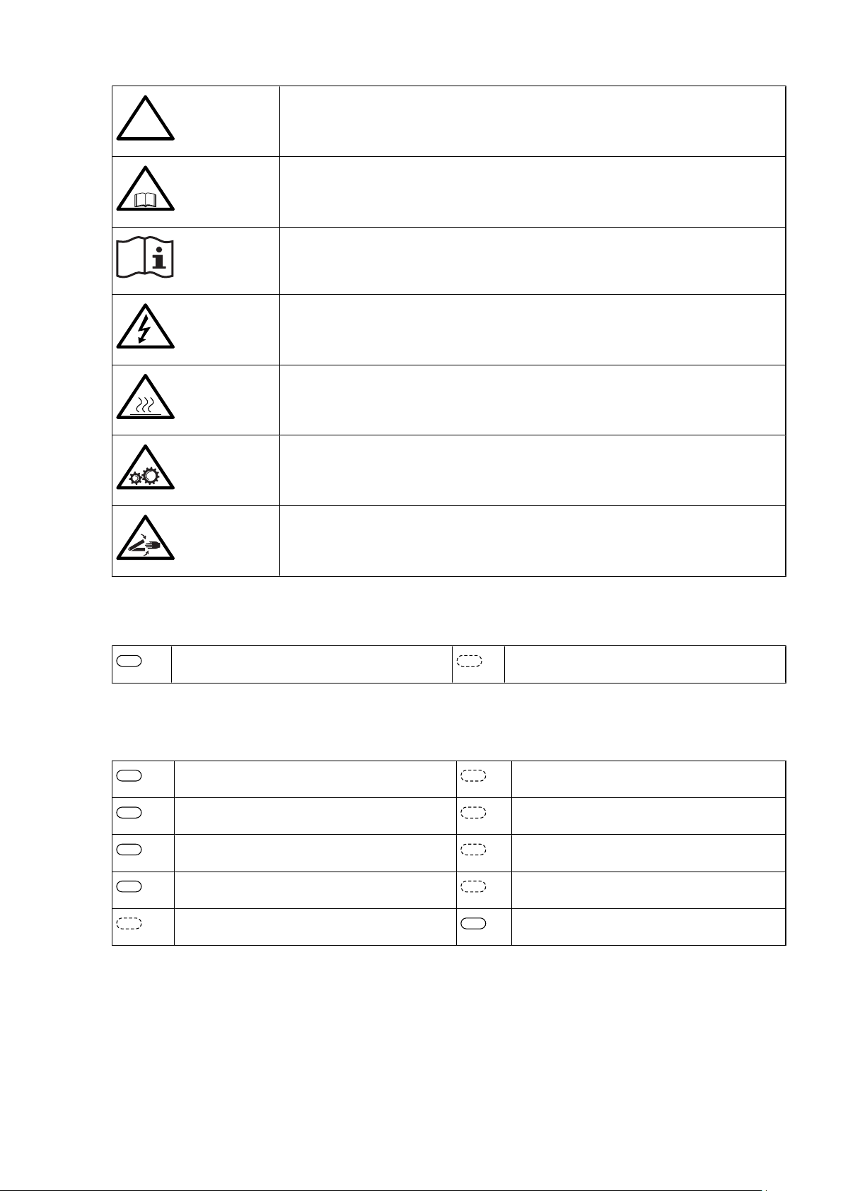
1.3 Symbols on decals
The following symbols can occur on decals on the different parts of the heat pump. Which symbols are used
depends on the heat pump model.
Installation instructions VMBMA1002 – 3
!
!
3
353
50
362
54
406
55
408
71
417
Warning, danger!
Read the documentation provided.
Read the documentation provided.
Warning, hazardous electrical voltage!
Warning, hot surfaces!
Electrical components
Component, normal Component, accessory
Outdoor unit
Outdoor sensor
Hot water sensor
Warning, moving parts!
Warning, risk of crushing injury!
Drip tray
Shunt valve
Room sensor
Sensor hot-water top
Flow guard
EVU
Defrost sensor
4 – Installation instructions VMBMA1002
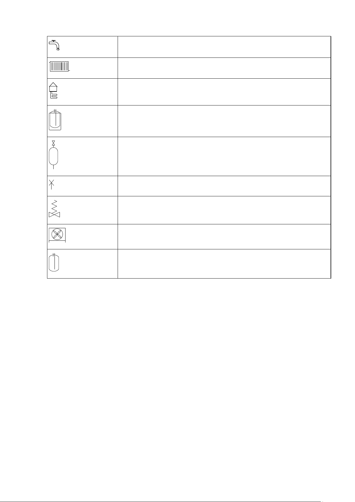
Pipe connections
Tap water
Heating system
Brine
Defrosting tank
Expansion tank with safety valve, brine
Bleeding
Temperature and pressure relief valve
Outdoor unit
Water heater
Installation instructions VMBMA1002 – 5
2 Important information/Safety regulations
Warning! Risk of personal injury! Children are not permitted to play with the product.
Warning! As the water temperature in DHP-H Opti Pro and DHP-L Opti Pro becomes extremely hot, a
mixer valve must be installed between the cold water and hot water pipes to ensure a lower domestic hot
water temperature.Alternatively the maximum hot water temperature must be reduced in the Service
menu.
Warning! Danfoss SP (1-phase) heat pumps have a factory installed safety valve for temperature and
pressure, (10 bar 90-95°C), in accordance with the requirements in Great Britain. This valve is located in the
water tank and may not be used for any purpose other than connecting the outlet pipe.
Also note that for heat pump DHP-H Opti Pro SP and DHP-L Opti Pro SP it is imperative that the hot water
temperature is changed from default setting 95°C to 85°C.
Caution! The heat pump must be installed by authorised installation engineers and the installation must
follow the applicable local rules and regulations as well as these installation instructions.
Caution! This product is not intended for persons (including children) with reduced physical, sensory or
psychological capacity, or who do not have knowledge or experience, unless supervised or they have
received instructions on how the apparatus functions from a safety qualified person.
Caution! The heat pump must be located in a frost-free environment!
Caution! The heat pump must be placed in an area with a floor drain.
Caution! The heat pump must be located on a stable base. The floor must be able to support the gross
weight of the heat pump with filled hot water tank (see Technical data).
Caution! To prevent leaks, ensure that there are no stresses in the connecting pipes!
Caution! It is important that the heating system is bled after installation.
Caution! Bleed valves must be installed where necessary.
6 – Installation instructions VMBMA1002
Caution! The hot water tank must be equipped with an approved safety valve.
Caution! Heating systems with closed expansion tanks must also be supplied with approved pressure
gauges and safety valves.
Caution! Cold and hot water pipes and overflow pipes from safety valves must be made of heat resistant
and corrosion-resistant material, e.g. copper. The safety valve overflow pipes must have an open
connection to the drain and visibly flow into this in a frost-free environment.
Caution! The connecting pipe between the expansion tank and the safety valve must slope continuously
upwards. A continuous upwards slope means that the pipe must not slope downwards from the
horizontal at any point.
Note! If there is any risk of groundwater infiltration at wall lead-ins for brine pipes, watertight grommets
must be used.
Note! In addition to applicable local rules and regulations the installation should be carried out in a
manner that prevents vibrations from the heat pump being transmitted into the house causing noise.
2.1 Refrigerant
Caution! Work on the refrigerant circuit must only be carried out by a certified engineer!
Although the heat pump cooling system (refrigerant circuit) is filled with a chlorine-free and environmentallyapproved refrigerant that will not affect the ozone layer, work on this system may only be carried out by authorized persons.
2.1.1 Fire risk
The refrigerant is not combustible or explosive in normal conditions.
2.1.2 Toxicity
In normal use and normal conditions the refrigerant has low toxicity. However, although the toxicity of the refrigerant is low, it can cause injury (or be highly dangerous) in abnormal circumstances or where deliberately abused.
Warning! Risk of personal injury! Spaces in which heavy vapour can collect below the level of the air must
be well ventilated.
Refrigerant vapour is heavier than air and, in enclosed spaces below the level of a door for example, and in the
event of leakage, concentrations can arise with a resultant risk of suffocation due to a lack of oxygen.
Installation instructions VMBMA1002 – 7
Warning! Risk of personal injury! Refrigerant exposed to a naked flame creates a poisonous irritating gas.
This gas can be detected by its odour even at concentrations below its permitted levels. Evacuate the area
until it has been sufficiently ventilated.
2.1.3 Work on the refrigerant circuit
Caution! When repairing the refrigerant circuit, the refrigerant must not be released from the heat pump,
it must treated in the appropriate way.
Draining and refilling must only be carried out using new refrigerant (for the amount and type of refrigerant see
manufacturer’s plate) through the service valves.
Caution! All warranties from Danfoss are void if, when filling with refrigerant other than Danfoss A/S
specified refrigerant, if there has not been written notification that the new refrigerant is an approved
replacement refrigerant together with other remedies.
2.1.4 Scrapping
Caution! When the heat pump is to be scrapped the refrigerant must be extracted for disposal. Local rules
and regulations related to the disposal of refrigerant must be followed.
2.2 Electrical connection
Caution! Electrical installation may only be carried out by an authorized electrician and must follow
applicable local and national regulations.
Caution! The electrical installation must be carried out using permanently routed cables. It must be
possible to isolate the power supply using an all-pole circuit breaker with a minimum contact gap of 3
mm. (The maximum load for externally connected units is 2A).
DANGER! Hazardous electrical voltage! The terminal blocks are live and can be highly dangerous due to
the risk of electric shock. All power supplies must be isolated before electrical installation is started. The
heat pump is connected internally at the factory, for this reason electrical installation consists mainly of
the connection of the power supply.
2.3 Commissioning
Caution! The installation may only be commissioned if the heating system and brine system have been
filled and bled. Otherwise the circulation pumps can be damaged.
8 – Installation instructions VMBMA1002

Caution! If the installation is only to be driven by an auxiliary heater during the installation, ensure that
the heating system is filled and the brine pump and compressor cannot be started. This is carried out by
setting the operating mode to AUX. HEATER.
Installation instructions VMBMA1002 – 9
110
1845 (±10)
455
596
528
300
440
40±10
1
2
610
80
4
7
8
6
5
9
3
110
1845 (±10)
455
596
528
300
440
40±10
1
2
610
80
4
7
8
6
5
9
3
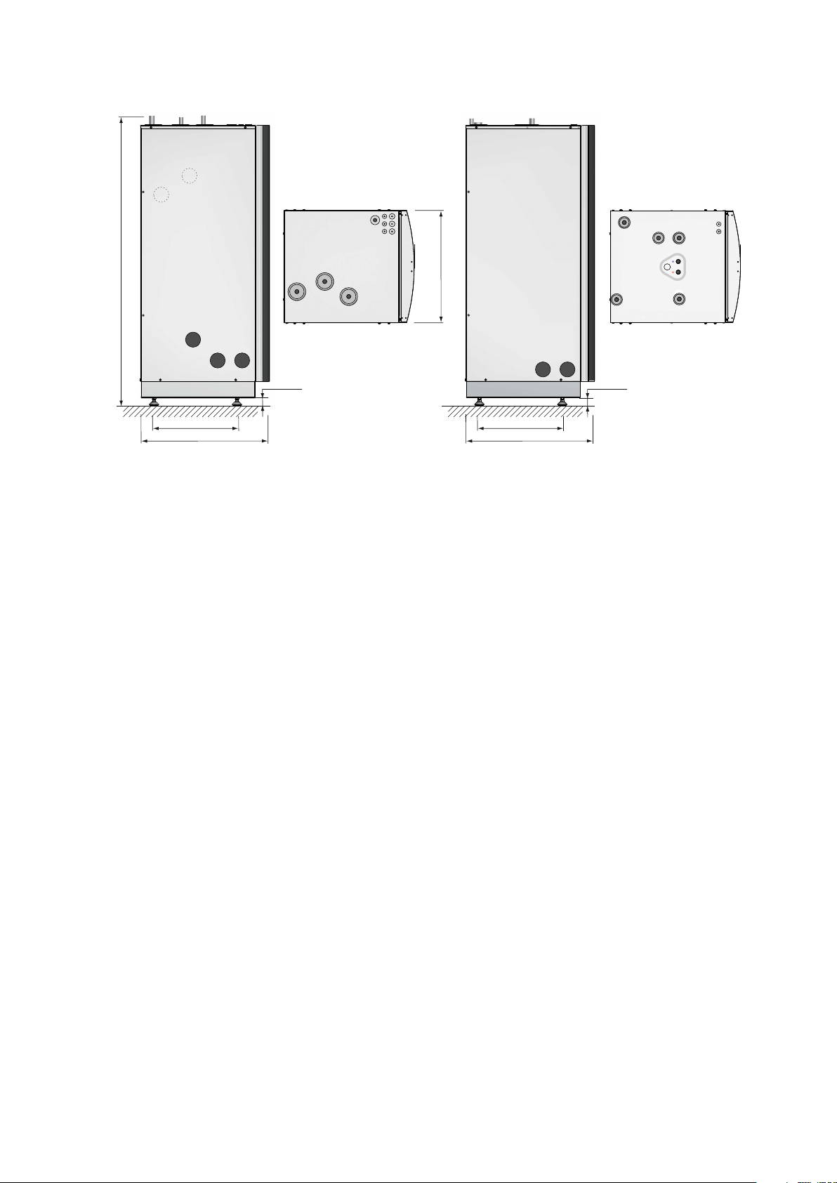
3 Heat pump data, dimensions and connections
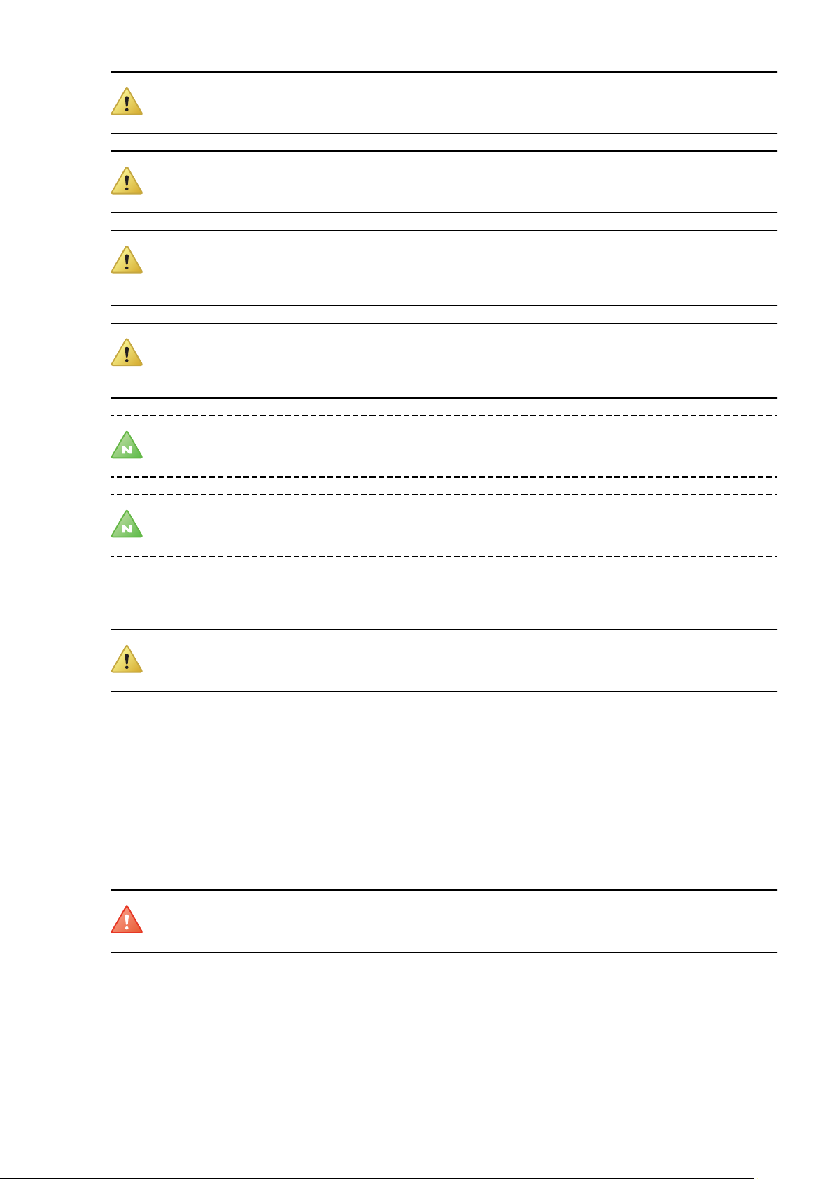
3.1 DHP-H, DHP-H Opti
Symbol explanation
1 Brine in, 28 Cu
2 Brine out, 28 Cu
3 Heating system supply pipe, 22 Cu: 4-10 kW, 28 Cu: 12-16 kW
4 Heating system return pipe, 22 Cu: 4-10 kW, 28 Cu: 12-16 kW
5 Connection for bleed valve, 22 Cu
6 Hot water line, 22 mm
7 Cold water line, 22 mm
8 Lead-in for supply, sensor and communication cables
9 Safety valve for temperature and pressure (only applies to
certain models)
The brine pipes can be connected on either the left or right-hand sides
of the heat pump.
Figure 1. Dimensions and connections
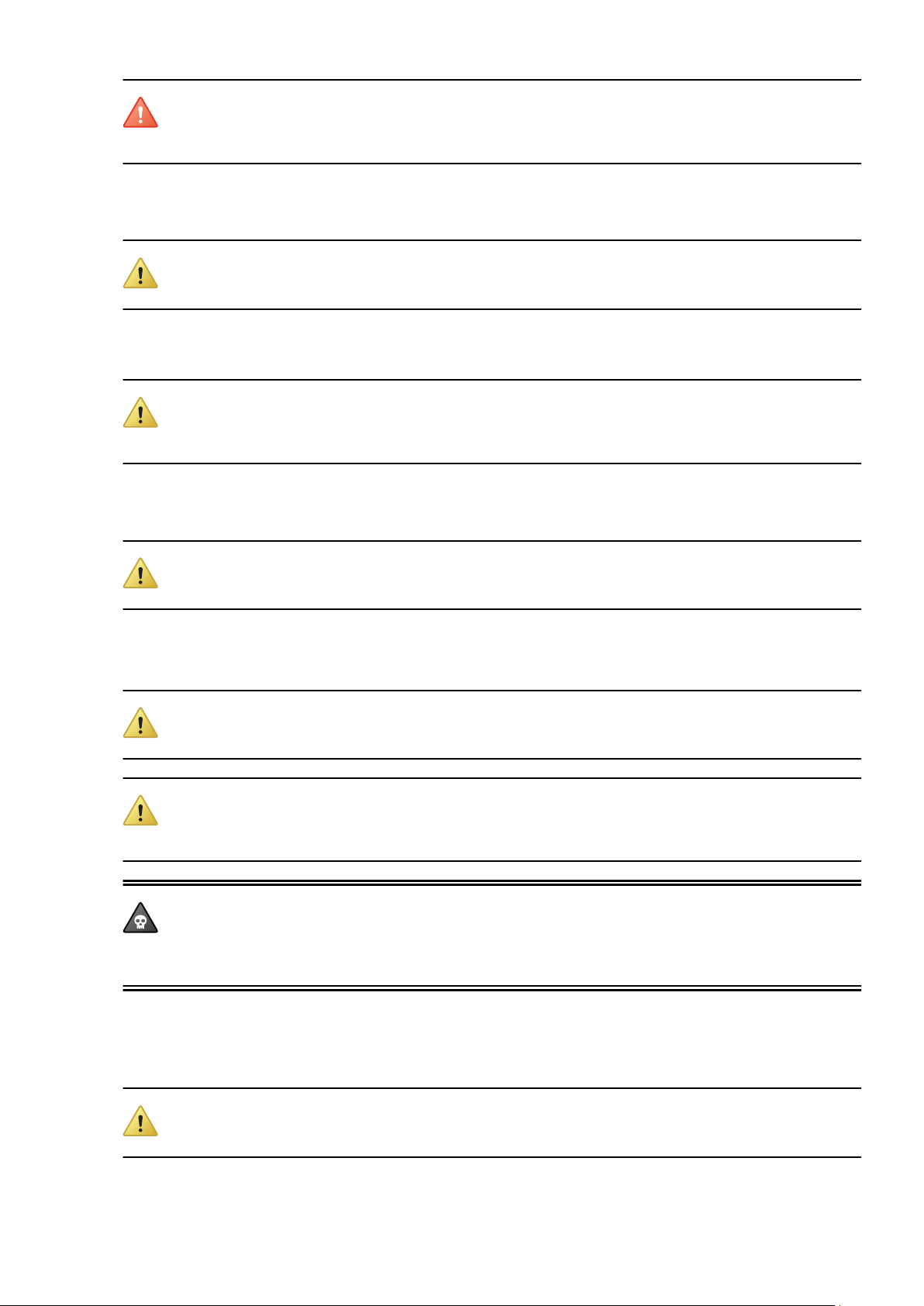
3.2 DHP-H Opti Pro
Symbol explanation
1 Brine in, 28 Cu
2 Brine out, 28 Cu
3 Heating system supply pipe, 22 Cu: 4-10 kW, 28 Cu:
12-16 kW
4 Heating system return pipe, 22 Cu: 4-10 kW, 28 Cu: 12-16
kW
5 Connection for bleed valve, 22 Cu
6 Hot water line, 22 mm
7 Cold water line, 22 mm
8 Lead-in for supply, sensor and communication cables
9 Safety valve for temperature and pressure (only applies
to certain models)
The brine pipes can be connected on either the left or right-hand sides
of the heat pump.
Figure 2. Dimensions and connections
10 – Installation instructions VMBMA1002
110
1845 (±10)
455
596
528
300
440
40±10
2
1
610
80
4
786
5
3
1538 (±10)
455
596
690
40±10
110
528
300
440
1
2
610
80
3
5
4
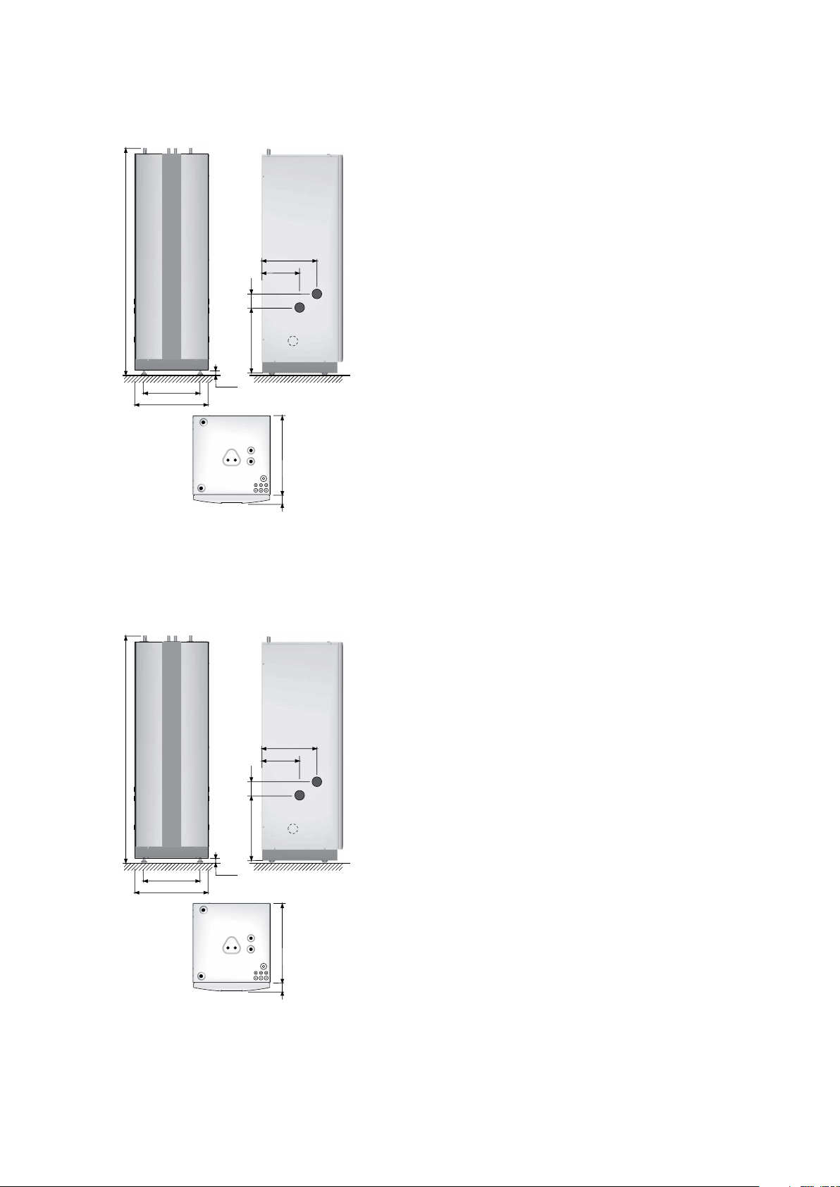
3.3 DHP-C
Symbol explanation
1 Brine in, 28 Cu
2 Brine out, 28 Cu
3 Heating system supply pipe, 22 Cu
4 Heating system return pipe, 22 Cu
5 Connection for bleed valve, 22 Cu
6 Hot water line, 22 mm
7 Cold water line, 22 mm
8 Lead-in for supply, sensor and communication cables
The brine pipes can be connected on either the left or right-hand sides
of the heat pump.
Figure 3. Dimensions and connections
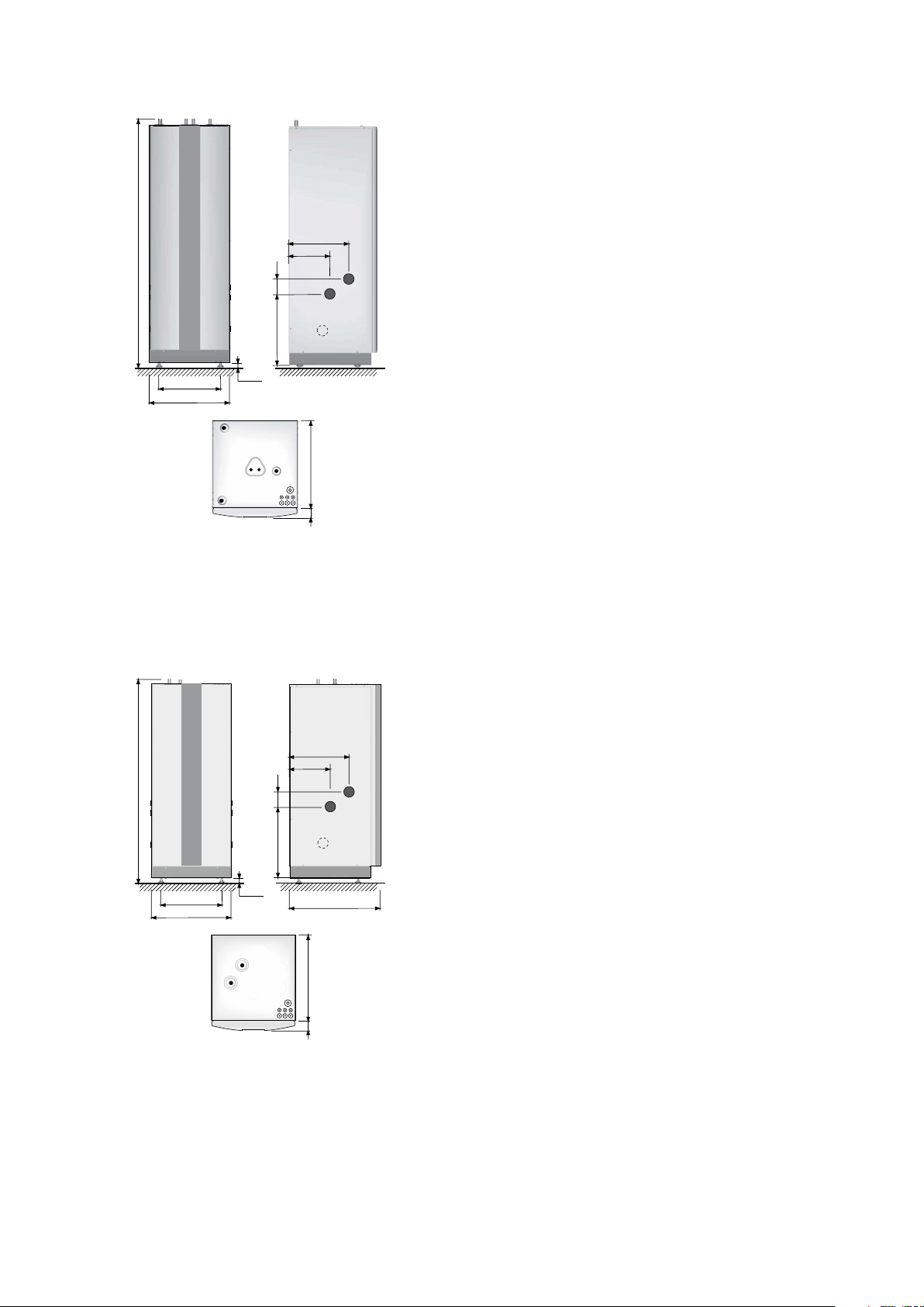
3.4 DHP-L, DHP-L Opti
Symbol explanation
1 Brine in, 28 Cu
2 Brine out, 28 Cu
3 Heating system supply pipe, 22 Cu: 4-10 kW, 28 Cu:
12-16 kW
4 Heating system return pipe, 22 Cu: 4-10 kW, 28 Cu: 12-16
kW
5 Lead-in for supply, sensor and communication cables
The brine pipes can be connected on either the left or right-hand sides
of the heat pump.
Installation instructions VMBMA1002 – 11

455
596
690
40 ±10
110
528
300
440
1
2
3
1538 (±10)
610
80
4
6
5
7
1845 (±10)
455
596
528
258
250
300
40±10
1
2
610
80
5
78
9
6
10
3
4
3.5 DHP-L Opti Pro
Figure 4. Dimensions and connections
Symbol explanation
1 Return line water heater, 22 (flexible hose)
2 Brine in, 28 Cu
3 Brine out, 28 Cu
4 Heating system supply pipe, 22 Cu: 4-10 kW, 28 Cu: 12-16
kW
5 Heating system return pipe, 22 Cu: 4-10 kW, 28 Cu: 12-16
kW
6 Supply line water heater, 22 Cu
7 Lead-in for supply, sensor and communication cables
The brine lines (2), (3) and return line water heater (1) can be connected
on the right or left-hand sides.
3.6 DHP-A, DHP-A Opti
Symbol explanation
1 Brine in, 28 Cu
2 Brine out, 28 Cu
3 Lead-in for supply, sensor and communication cables
4 Heating system supply pipe, 22 Cu: 6-10 kW, 28 Cu: 12 kW
5 Heating system return pipe, 22 Cu: 6-10 kW, 28 Cu: 12 kW
6 Connection for bleed valve, 22 Cu
7 Hot water line, 22 mm
8 Cold water line, 22 mm
9 Expansion outlet brine circuit, R25 int.
10 Safety valve for temperature and pressure (only applies to
certain models)
The brine pipes can be connected on either the left or right-hand sides
of the heat pump.
Figure 5. Dimensions and connections
12 – Installation instructions VMBMA1002
3
5
6
2
11
15
14
10
12
13
17
7
16
4
89
1
1538 (±10)
455
596
690
40±10
455
690
40±10
3.7 DHP-AL, DHP-AL Opti
The brine pipes can be connected on either the left or right-hand sides of the heat pump.
Figure 6. Dimensions and connections heat pump and water heater
Symbol explanation
Heat pump
1 Brine in, 28 Cu 5 Heating system supply pipe, 22 Cu: 6-10 kW, 28 Cu: 12
kW
2 Brine out, during normal operation, 28 Cu 6 Heating system return pipe, 22 Cu: 6-10 kW, 28 Cu: 12 kW
3 Brine out during defrosting to hwh pos 8, 28 Cu 7 Lead-in power and sensor lead
4 Return line from water heater pos 9, 28 Cu
Symbol explanation
Water heater
8 Connection for brine out when defrosting from
pos 3
9 Water heater, return pipe to pos 4 14 Supply to water heater coil
10 Bleed valve, at stainless steel water heater 15 Brine, expansion outlet when outdoor unit is positioned at
11 Brine out during defrosting, 28 Cu 16 Lead-in sensor lead
12 Hot water line, 22 mm 17 Safety valve for temperature and pressure (only applies to
13 Cold water line, 22 mm
high level
certain models)
Installation instructions VMBMA1002 – 13
1
12
2
1175
630
405
441
342
300
120
910
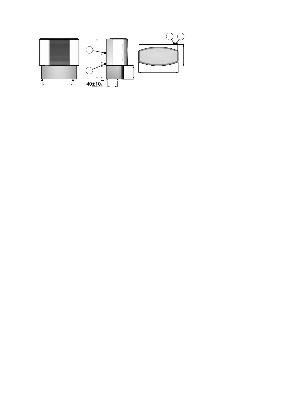
3.8 Outdoor unit DHP-A, DHP-AL, DHP-A Opti, DHP-AL Opti
Figure 7. Outdoor unit, dimensions and connections.
Symbol explanation
1 Brine in, 28 Cu
2 Brine out, 28 Cu
14 – Installation instructions VMBMA1002
4 Transport, unpacking and setting-up
4.1 Transporting the heat pump
Caution! During transportation or lifting of the entire heat pump, the front panel must always be installed
as it locks the other panels construction.
Caution! The heat pump must always be transported and stored in a dry area. Secure the heat pump so
that it cannot tip over during transportation.
When transporting indoors to the installation location it may be necessary to place the heat pump on its back. The
time that the heat pump is transported on its back should be as short as possible. After the heat pump has been
lifted up again it must stand upright for at least an hour before commissioning.
4.2 Unpacking heat pump
4.2.1 Delivery check
1. Check that there is no transport damage. The heat pump is packaged in cardboard.
2. Remove the packaging and check that the delivery contains the following components.
Safety valve 9 bar 1/2" 086U2369 1 1
Safety valve 1.5 bar 1/2" 086U0896 1 1
Outdoor sensor 086U2701 1 1
Expansion and bleed tank 086U2824 1 1
Rubber bellows for 22-28 mm hole 086U3423 5 5
Flexible hose R20 L=550 086U6033 2 -
Flexible hose R25 L=550 086U6034 - 2
Filler device DN25 086U6006 1 -
Filler device DN32 086U6007 - 1
Dirt filter with shut-off DN20 086U3427 1 -
Dirt filter with shut-off DN25 086U6005 - 1
Manual holder 086U3988 1 1
4.3 Setting-up the heat pump
4.3.1 Recommended location
Part number 4-10 kW 12-16 kW
Caution! To avoid condensation problems for the brine lines, as short a brine line as possible is
recommended indoors.
The heat pump should be located on a stable floor, preferably made of concrete. When locating the heat pump on
a wooden floor this should be reinforced to take the weight of the heat pump including a filled water heater, see
technical data for relevant heat pump. One solution is to place a thick metal plate, at least 6mm, under the heat
pump. The metal plate should cover several joists spreading the weight of the heat pump over a larger area. If the
heat pump is being installed in a newly-built house, this has normally been taken into account during construction, and the joists where the heat pump will be located have been reinforced. Always check that this has been
carried out when installing into a newly-built house.
Installation instructions VMBMA1002 – 15
300 mm
300 mm
300 mm
10 mm
600 mm
1905
1620
Avoid positioning the heat pump in a corner as the surrounding walls may amplify its noise. It is also important to
adjust the heat pump using the adjustable feet so that it is horizontal to the base.
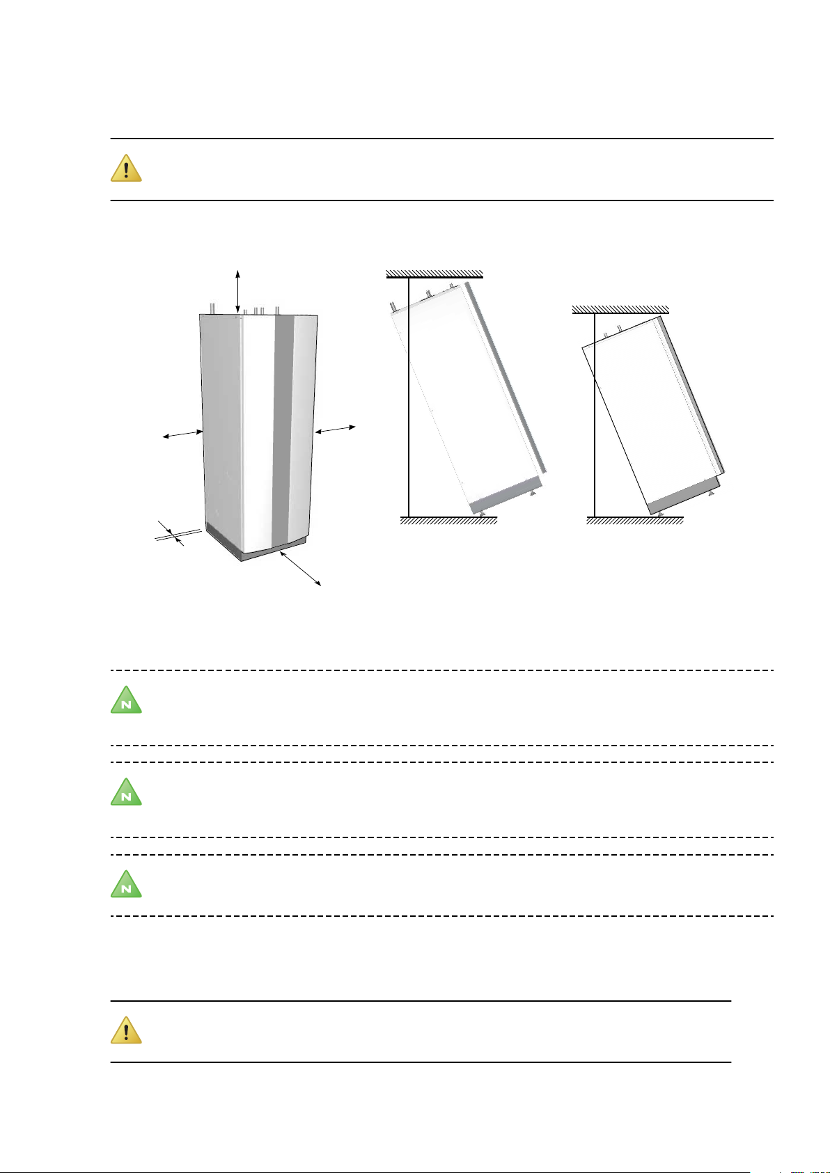
4.3.2 Space requirement
Caution! The heat pump must not be enclosed as the temperature inside the cabinet becomes extremely
high.
To facilitate the installation and subsequent testing and maintenance there must be sufficient free space around
the heat pump in accordance with the following image:
4.3.3 Setting up
Note! The heat pump has feet that can be adjusted to compensate for irregularities in the surface on
which it is sitting. If the surface is so irregular that the feet cannot compensate for it, the installation
engineer must remedy this.
Note! It is recommended that the condensation drain is installed from the drip tray’s drain pipe by lying
the heat pump down. The drain pipe opens through a hole in the base plate and has a Ø10 mm hose
connection.
Note! If the heat pump has been laid down it is recommended that it stands upright for at least an hour
before commissioning.
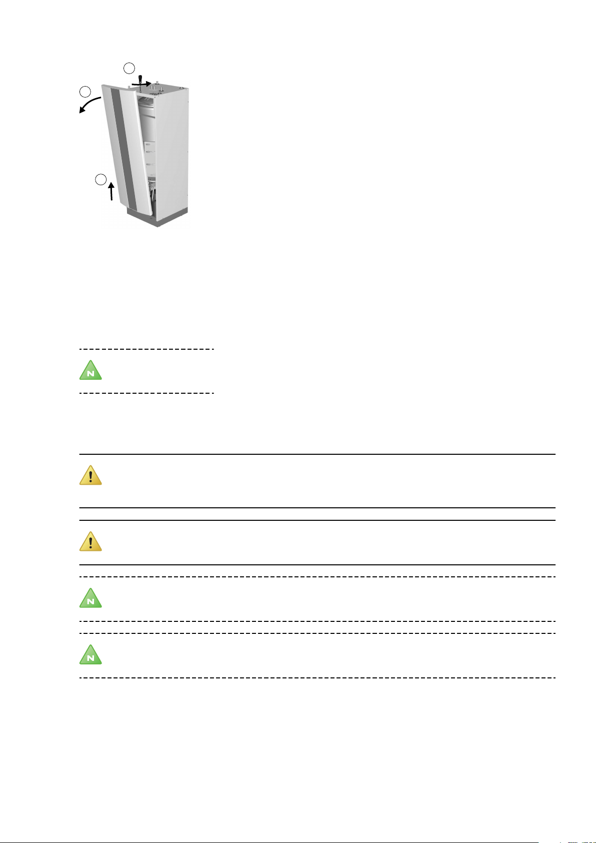
4.3.4 Removing the front cover
Caution! Do not damage the electrical wiring for the display when the front cover is removed!
16 – Installation instructions VMBMA1002
1
2
3
To install the heat pump the front cover must be removed.
Figure 8. Removing the front cover
1. Press against the front cover and turn the catch 90° degrees anti-clockwise to release the front cover.
2. Tilt the front cover outwards.
3. Lift the front cover upwards to remove it from the heat pump.
4.4 Setting-up the outdoor unit
Note! Applies to DHP-A.
4.4.1 Recommended location
When positioning the outdoor unit, note the following:
Caution! When the outdoor unit is defrosting, water will drip straight down under the unit. The area
around the outdoor unit must therefore be properly drained in order to take the water (approximately 2
litres per defrost).
Caution! The outdoor unit’s adjustable stand must be positioned on a secure base such as wooden
sleepers, paving slabs or cast footings.
Note! The outdoor unit does not have to be positioned in any specific direction.
Note! Noise is produced from the outdoor unit when the fan is in operation, remember this when
positioning to reduce disturbance in your own home as well as to any neighbours.
Installation instructions VMBMA1002 – 17
300 mm
300 mm
300 mm
1500 mm
1
1
2
3
4.4.2 Space requirement
Figure 9. Necessary service space for outdoor unit.
4.4.3 Unpacking
The outdoor unit is packed and delivered in a crate.
1. Start by unpacking the unit from the crate.
2. Check that the delivery is complete, it must contain the outdoor unit, front cover, cover as well as a disassembled stand including necessary screws, nuts and washers.
4.4.4 Installation
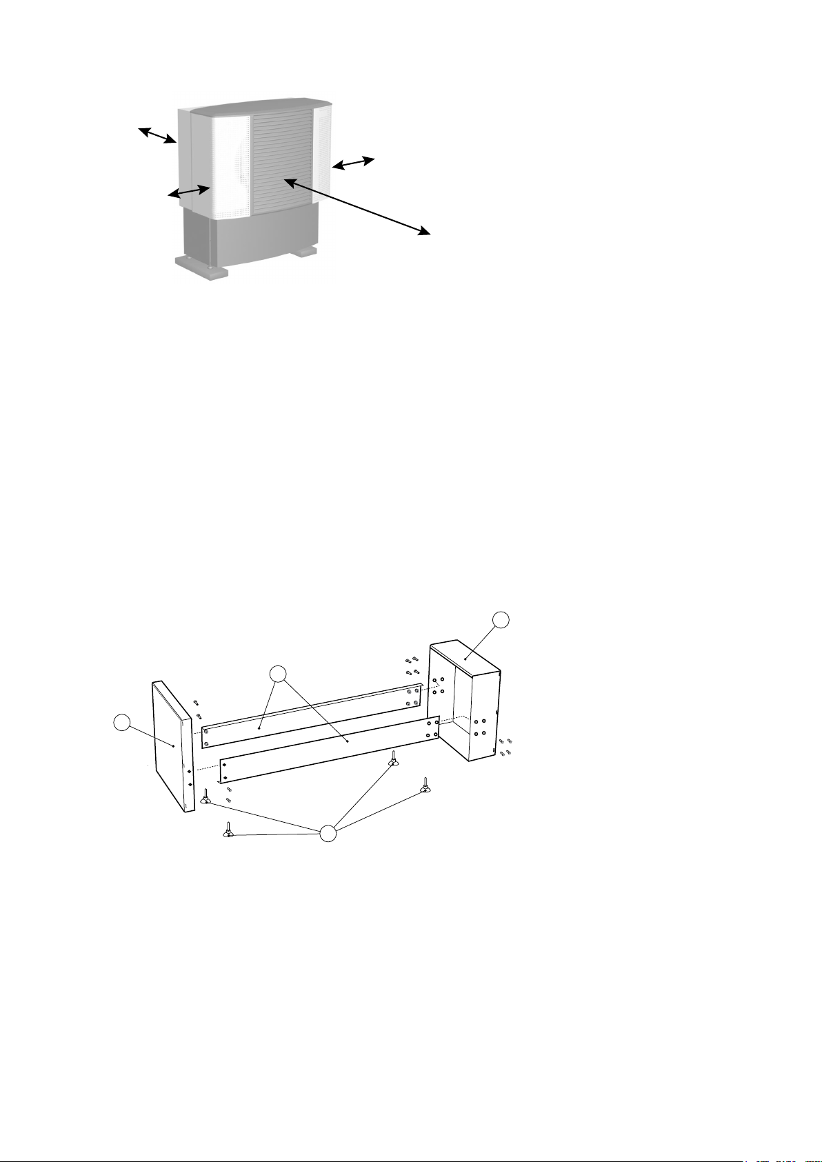
4.4.4.1 Assembling the stand
Assemble the stand
1. Screw the two horizontal struts together (2) using the two ends (1) as illustrated below. Use 10 x M6x10
screws. The curved edges of the horizontal struts must be facing inwards.
Figure 10. Assembling the stand
Symbol explanation
1 Ends
2 Strut
3 Feet
2. Screw the adjustable feet (3) into the holes under the ends.
4.4.4.2 Preparing the outdoor unit
While the outdoor unit remains on the pallet it should be prepared for placing on the stand. Carry out the following:
18 – Installation instructions VMBMA1002
1. There are three M6x20 screws on the lower edge of the outdoor unit. Unscrew them so that 2-3 mm of the
thread remains. Use a torx TX25 screwdriver, or equivalent.
Caution! Do not lift the outdoor unit by its side panels when it is to be raised or moved.
2. Raise the outdoor unit.
3. Remove the side plates. They are held in place by clamps and so are removed by pulling outwards.
4. Remove all four screwed lifting eyes. Use a 13 mm wrench, or equivalent.
4.4.4.3 Assembling the outdoor unit on the stand
1. Lift the outdoor unit into the place on the stand.
2. Screw the outdoor unit onto the stand. Use 4 x M6x20 screws. It may be necessary to push and pull the
stand slightly in order to get the screw holes to align.
Caution! When filling the brine system the outdoor unit must be bled using the bleed screws on
the connecting pipes inside the side covers. We recommend that you return to this instruction after
the brine system has been filled.
3. Reinstall the side panels.
4.4.4.4 Assembling the defrost sensor
Figure 11. Hook the defroster sensor mounting into place
1. Slide the mounting for the defroster sensor into the hole on the reverse of the outdoor unit until the cover
hooks into place on the edge.
2. Take out the defrosting sensor from the electrical connection box. Thread out the sensor through a suitable
lead-in.
3. Route the defroster sensor connection cable through the cable lead-in to the mounting.
4. Secure the defroster sensor at the bottom of the mounting using a cable tie.
4.4.4.5 Assembling the front cover
1. Hook the lower edge of the front cover onto at least one of the three screws in the bottom edge of the
stand.
2. Secure the upper edge of the front panel temporarily in the centre hole. Use 1 x M6x15 torx TX25.
3. Align all the three screws in the lower edge.
4. Screw the three screws in the lower edge fully. Use a torx TX25 screwdriver, or equivalent.
Installation instructions VMBMA1002 – 19

5. Secure the front panel's upper edge with the 2 x remaining M6x15 torx TX25, see figure below.
Figure 12. Secure the cover
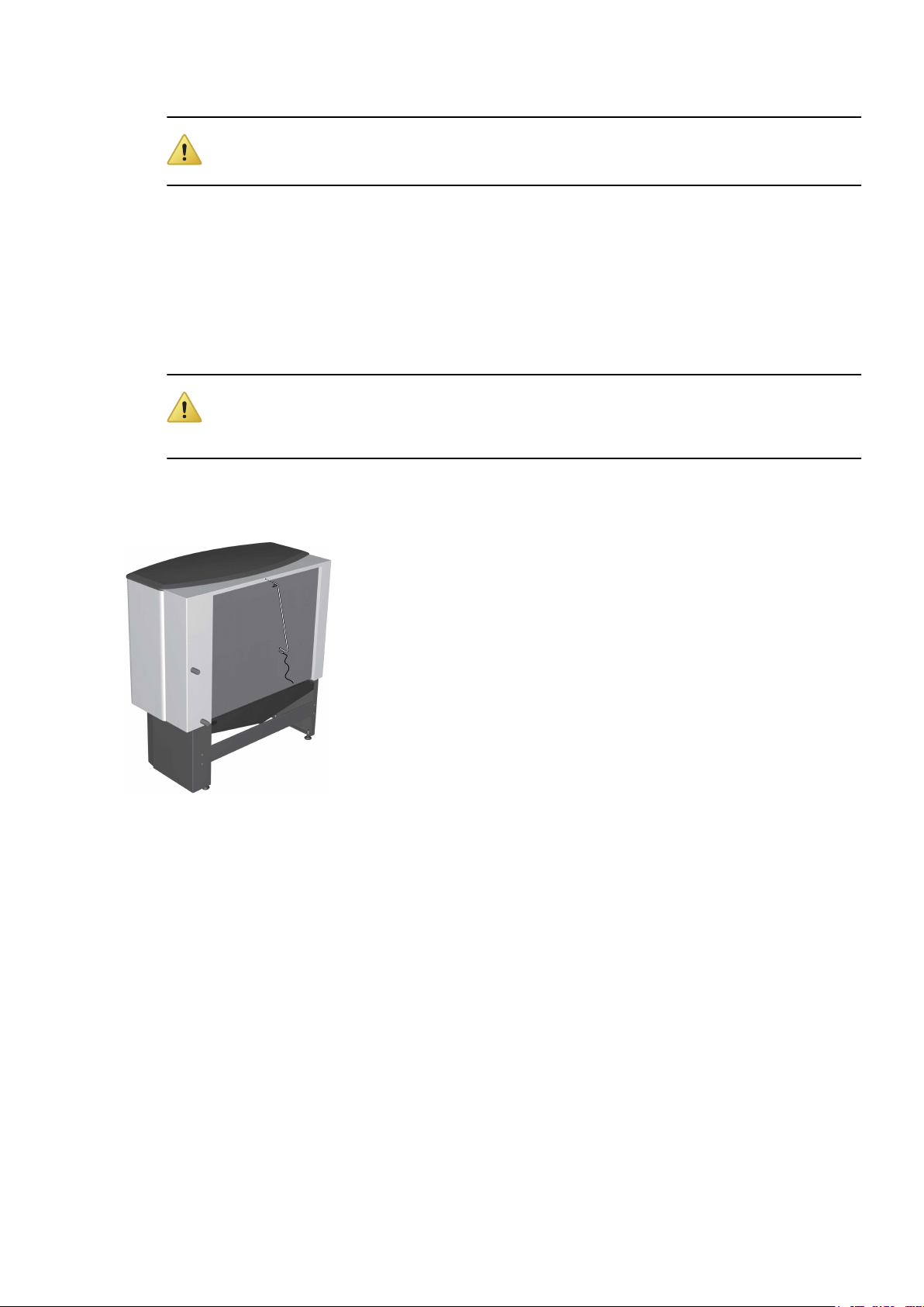
4.4.4.6 Install the cover
1. Hook the cover at the front edge on the front cover.
Figure 13. Hook the front cover into place
1. Secure the cover using a screw on each side. Use 2 x cross head screws.
If the cover does not align with the side cover plates it may be necessary to drill new 3 mm holes:
Mark for the new holes
•
Lift off the cover
•
Drill the holes
•
Install and screw the cover into place
•
Figure 14. Screw the front cover into place
20 – Installation instructions VMBMA1002

4.4.4.7 Install cover
1. Hook the cover onto the stand.
Figure 15. Hook the cover onto the stand.
Installation instructions VMBMA1002 – 21
 Loading...