

Page 1

Danfoss Gas Sensor
Type DGS
Modbus or Service Tool display operation
User Guide
danfoss.com
Page 2

Contents Page
1. Intended use .....................................................................................4
2. Content ..........................................................................................4
3. Operation ........................................................................................4
3.1 Function of the keys and LEDs on the keypad ................................................6
3.2 Setting / changing of parameters and set points .............................................6
3.3 Code Levels.................................................................................7
4. Menu Overview ..................................................................................7
4.1 Error status ............................................................................... 10
4.2 Alarm Status .............................................................................. 10
4.3 Relay Status............................................................................... 10
4.4 Menu Measuring Values ................................................................... 11
4.5 Display Parameters........................................................................ 11
4.5.1 Software Version ........................................................................ 11
4.5.2 Language . . . . . . . . . . . . . . . . . . . . . . . . . . . . . . . . . . . . . . . . . . . . . . . . . . . . . . . . . . . . . . . . . . . . . . . . . . . . . . . 12
4.5.3 LCD Function Check . . . . . . . . . . . . . . . . . . . . . . . . . . . . . . . . . . . . . . . . . . . . . . . . . . . . . . . . . . . . . . . . . . . . . 12
4.6. Measuring Point Parameters ..............................................................12
4.6.1 Alarm limits ............................................................................. 12
4.6.2 Alarm delay ............................................................................. 12
4.7 Menu System Parameters..................................................................13
4.7.1 AO function .............................................................................13
4.8 Operating data............................................................................ 14
4.9 Calibration................................................................................ 15
4.9.1 Zero Calibration .........................................................................16
4.9.2 Gain Calibration .........................................................................17
4.9.3 Zero-point calibration of Analog output.................................................. 18
4.10 Addressing .............................................................................. 18
5. Modbus menu survey .......................................................................... 19
6. Technician use only! ............................................................................ 22
6.1 Regular test............................................................................... 22
6.2 Locaton................................................................................... 22
7. Ordering . . . . . . . . . . . . . . . . . . . . . . . . . . . . . . . . . . . . . . . . . . . . . . . . . . . . . . . . . . . . . . . . . . . . . . . . . . . . . . . . . . . . . . . 23
User Guide | Danfoss Gas sensor. Type DGS. Modbus or Service Tool display operation
2 | RS8KD102
© Danfoss | DCS (ADAP-KOOL®) | 2018.12
Page 3

User Guide | Danfoss Gas sensor. Type DGS. Modbus or Service Tool display operation
© Danfoss | DCS (ADAP-KOOL®) | 2018.12
RS8KD102 | 3
Page 4
User Guide | Danfoss Gas sensor. Type DGS. Modbus or Service Tool display operation
4 | RS8KD102
© Danfoss | DCS (ADAP-KOOL®) | 2018.12
1
Intended use
The display of the handheld Service Tool and the
Modbus interface for integration with Building
Management Systems is used as interface for
operation, commissioning and calibration of the
DGS gas detection unit
2
Content
This user guide contains the maximum possible
functionality of concerned display devices.
Depending on the DGS type some features
described here are not possible and therefore the
menu items may be hidden.
Some features are available from Modbus or
handheld Service Tool interface only. Differences
is highlighted in this document.
3
Operation
The configuration and service is made via the
handheld Service Tool or in combination with the
Modbus interface.
Security is provided via password protection
against unauthorized intervention.
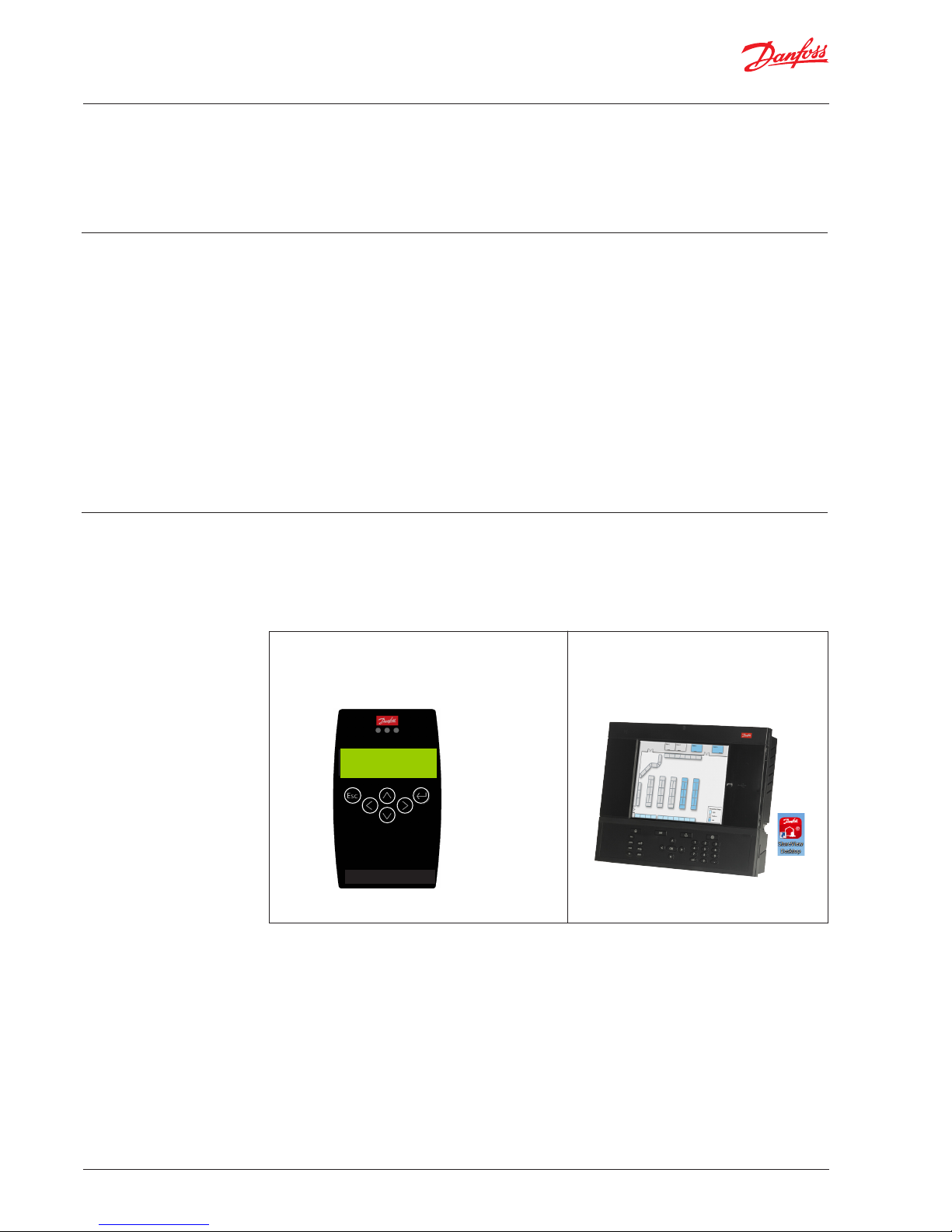
Handheld Service Tool:
Operation is done via 6 buttons.
AK-SM 800 Front End:
The configuration is done via the graphical
display and buttons or via the PC tools
StoreView Desktop or AK-ST 500.
Gas D etection Service Tool
Esc
←─
D1 CO2 ppm
Warm-up Time
DGS Service Tool
Page 5
User Guide | Danfoss Gas sensor. Type DGS. Modbus or Service Tool display operation
© Danfoss | DCS (ADAP-KOOL®) | 2018.12
RS8KD102 | 5
Operation with the handheld Service Tool is
described in sections 3.1 and 3.2 and chapter 4.
Operation with the Danfoss Front End is
described in chapter 5.
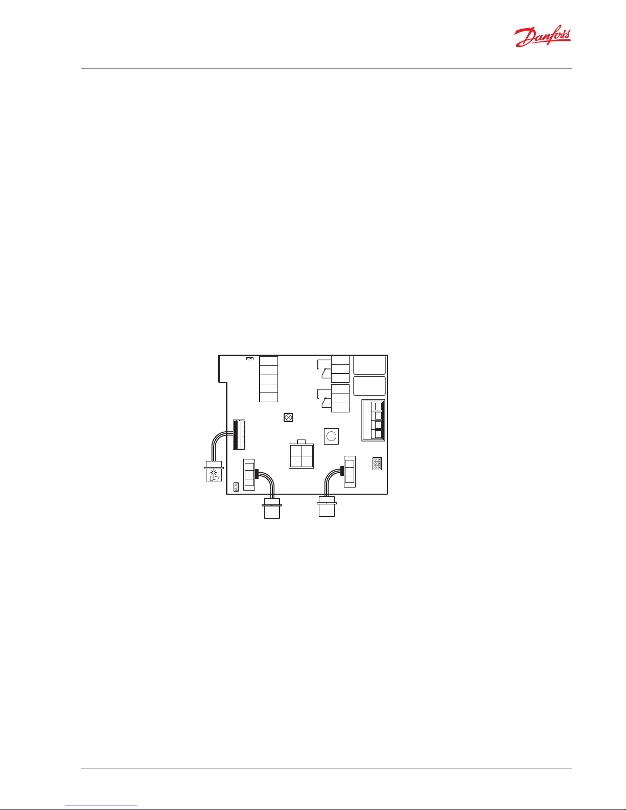
2 functions are configured via jumpers on the
DGS.
Jumper 4, JP 4, located on the bottom left is used
to configure the Modbus baud rate.
As default the baud rate is 38.400 Baud. By
removing the jumper the baud rate is changed to
19.200 Baud. Removing the jumper is required for
integrating with Danfoss System Managers AKSM 720 and AK-SM 350.
Jumper 5, JP5, located on the top left is used to
configure the analogue output type.
As default this is Voltage output. By removing the
jumper this is change to Current output.
Note: the DGS must be power cycled before any
change to JP4 take effect.
JP5
5
4
2
1
not used
GND
AO_01
DI_01
S&H supply
x1
open: 0-20mA
closed: 0-10V
LED
Yellow/Green/Red
1
2
3
1
2
3
x6
x5
Rel. 3
Rel. 1
x4
4
3
2
1
not used
JP3
JP2
JP1
x3
Ackn.-/Test
button
Sensor 1
Sensor 2
Tool
x9
x2
x8
B&L
JP4
Danfoss
80Z790.1
1
open: 19200 Baud
closed: 38400 Baud
BModbus
A+
-
24V ac/dc
+
(critical)
(warning)
Page 6
User Guide | Danfoss Gas sensor. Type DGS. Modbus or Service Tool display operation
6 | RS8KD102
© Danfoss | DCS (ADAP-KOOL®) | 2018.12
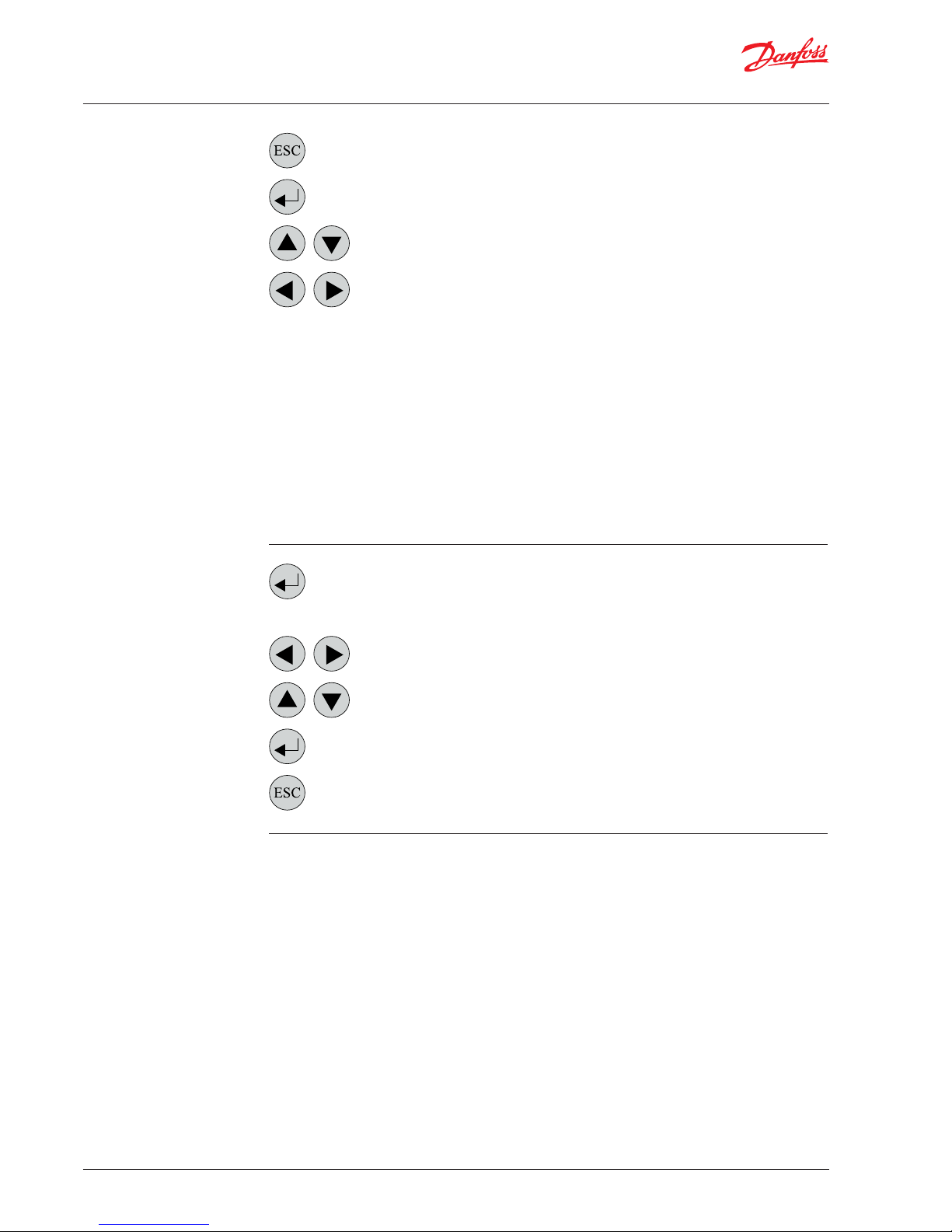
3.1
Function of the keys and LEDs
on the keypad
Exits programming, returns to the previous menu level.
Enters sub menus, and saves parameter settings.
Scrolls up & down within a menu, changes a value.
Change of cursor position.
The status LEDs indicate the operating state.
• Green
Continuous = Operating voltage
Flashing = Maintenance message
• Yellow
Continuous = Failure
Slowly flashing = Warming-up
Fast flashing = Special mode
• Red = Alarm
The backlight of the display changes from green
to red when an alarm is active.
3.2
Setting / changing of
parameters and set points
Open desired menu window.
Code input field opens automatically, if no code is approved.
Set the desired parameter / set point with the keys.
After input of valid code the cursor jumps onto the first position segment to be changed.
Push the cursor onto the position segment, which has to be changed.
Save the changed value, confirm storage (ENTER).
Cancel the save / close editing / return to a higher menu level (ESCAPE function).
Page 7
User Guide | Danfoss Gas sensor. Type DGS. Modbus or Service Tool display operation
© Danfoss | DCS (ADAP-KOOL®) | 2018.12
RS8KD102 | 7
3.3
Code Levels
All inputs and changes are protected by a
four-digit numeric code (= password) against
unauthorised intervention according to the
regulations of all national and international
standards for gas warning systems. The menu
windows of status messages and measuring
values are visible without entering a code.
The access to the protected features is cancelled
automatically if no button is pushed within 15
minutes.
The service technician access code to the
protected features is ‘1234’
4
Menu Overview
Menu operation is done via a clear, intuitive and
logical menu structure. The operating menu
contains the following levels:
• Starting menu with indication of the device
type if no Measuring Point is registered,
otherwise scrolling display of the gas
concentrations of all registered sensors in
5-second intervals. If alarms are active, only the
values of the sensors currently in alarm status
are displayed.
• Main menu
• 5 sub menus under “Installation and
Calibration”
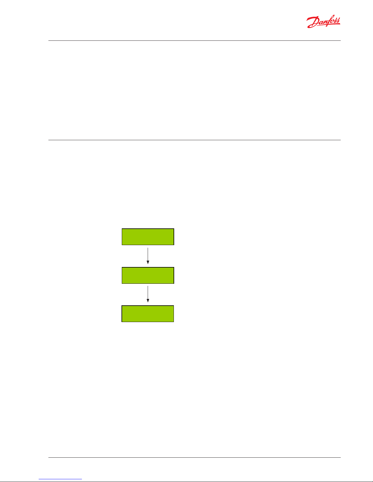
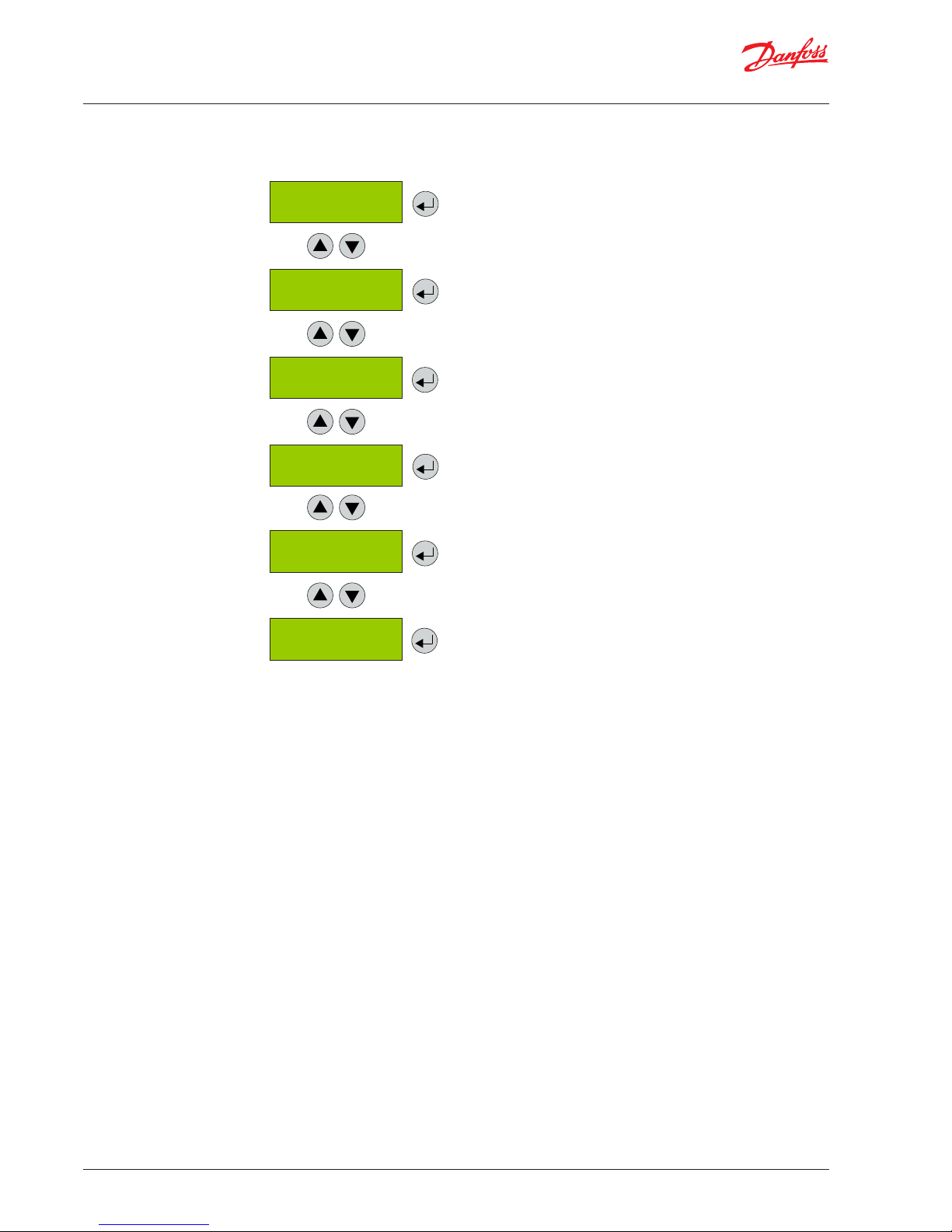
Power On Time of the basic device
Second counter counts down, when communication display <> basic
device is OK. In case of communication error the count-down will stop.
“Warm-up Time” is displayed. As soon as the sensor warm-up time has
expired, the measured value is displayed = measuring mode.
Seconds indicator = 0
After about 2 seconds
Power On Time
19s
Danfoss
DGS
D1 CO2 ppm
Warm-up Time
Page 8
User Guide | Danfoss Gas sensor. Type DGS. Modbus or Service Tool display operation
8 | RS8KD102
© Danfoss | DCS (ADAP-KOOL®) | 2018.12
4
Menu Overview
(Continued)
Starting menu
Main menu
Error Status
Alarm Status
Relay
Status
Measuring Values
Display
Parameters
Installation &
Calibration
Reading and acknowledgement of errors
See chapter 4.1
Display of the status of active alarms
See chapter 4.2
Display of the relay status. Protected by password.
See chapter 4.3
Display of measuring values
See chapter 4.4
Read-out of handheld tool version, language and set-up of language.
Partly protected by password
See chapter 4.5
Reading and change of the relay, measuring point and
system parameters as well as test and calibration functions
Chapter #
Page 9

User Guide | Danfoss Gas sensor. Type DGS. Modbus or Service Tool display operation
© Danfoss | DCS (ADAP-KOOL®) | 2018.12
RS8KD102 | 9
Service
OFF
MP Parameters
System Parameters
See chapter 4.6
See chapter 4.7
The following menu items are only accessible
with Service ON (password protected)
!! Service ON = Special mode = Fault message is
active!!
4
Menu Overview
(Continued)
Starting menu
Main menu Chapter #
Operating Data
See chapter 4.8
MP Parameters
See chapter 4.9
Calibration
Addressing
See chapter 4.10
Page 10

User Guide | Danfoss Gas sensor. Type DGS. Modbus or Service Tool display operation
10 | RS8KD102
© Danfoss | DCS (ADAP-KOOL®) | 2018.12
4.1
Error status
A pending fault activates the yellow LED (Fault).
The integrated fault management records the
first 99 occurred faults with time stamps in the
menu „System Errors“.
4.2
Alarm Status
Display of the currently pending alarms in plain
text in the order of their arrival. Only those
measuring points are displayed, where at least
one alarm is active.
Alarms in latching mode (latching mode is only
valid for certain DGS types, DGS-PE) can be
acknowledged in this menu (only possible if the
alarm isn’t active).
Alarm Status DP 1
“A1
DP 1
Acknowledge?
Symbol Description Function
DP 1 Measuring Point No.
1 = Relays 1 = Warning relay
2 = Buzzer
3 = Relay 3 = Critical relay
‘A1
‘‘A1
Alarm status
‘A1 = Alarm 1 active
‘‘A1 = Alarm 1 in latching mode, can be acknowledged
4.3
Relay Status
Reading of the current status of alarm relays.
The actual relay status is displayed, depending on
the relay mode (energized <> de-energized).
Selection of the alarm relay 1 – X
Alarm Relay
Status
Alarm Relay 1
Status OFF
Symbol Description Function
1 Alarm Relay Alarm relay = 1 - X
OFF Relay Status Relay OFF = coil de-energised
ON Relay Status Relay ON = coil energised
Selection of the next alarm relay
A number of error messages may be displayed
related to the sensor; Out of Range, Wrong type,
Removed, Calibration due, Voltage Error
“Voltage Error” refers to the supply voltage. In
this case the product will not go into normal
operation until the supply voltage is within the
specified range.
Note:
Relay 3 is Normally Closed with a fail-safe function at
power loss, i.e. in normal operation without any errors
or alarms, the coil is energised (Relay ON)
Page 11

User Guide | Danfoss Gas sensor. Type DGS. Modbus or Service Tool display operation
© Danfoss | DCS (ADAP-KOOL®) | 2018.12
RS8KD102 | 11
4.4
Menu Measuring Values
In this menu, the display shows the measuring
value with gas type and unit.
Measuring Values D 1 CO2 ppm
A ! 450
Symbol Description Function
D1 Actual Modbus address D1: Modbus address = 1
CO2 Gas type Display of gas type (must comply with gas type of sensor head)
ppm Gas unit Unit
51.0 C Measured value Current measured value (current value) of the gas concentration
A! Alarm indication At least one alarm has been released at this Measuring Point
# Maint. info Sensor head: maintenance due (maintenance date exceeded)
? ConfigError Gas type or meas. range doesn’t agree with sensor head.
Comm. err. Fault Measuring Point Communication error, sensor head <> I/O board
Underrange
Overrange
Meas. range monitoring
Meas. signal < admissible range (< zero point – 6 %)
Meas. signal > admissible range (> full scale value + 6 %)
Locked Measuring Point locked Measuring Point was temporarily locked by the operator.
Warm-up Warm-up time Warm-up time of the sensor active
Selection of the next measuring point
4.5
Display Parameters
In the menu Display Parameters you can find the
general parameters of the display.
Display
Parameters
4.5.1
Software Version
Software Version
XXXXX - YYYYY
Software version of the handheld Service Tool
and of DGS.
Symbol Description Function
XXXXX Software Version of the Service Tool XXXXX Software Version
YYYYY Software Version of the DGS YYYYY Software Version
Page 12

User Guide | Danfoss Gas sensor. Type DGS. Modbus or Service Tool display operation
12 | RS8KD102
© Danfoss | DCS (ADAP-KOOL®) | 2018.12
4.5.2
Language
Language
English
Selection of the menu language (password
protected)
Symbol Description Default Function
English Language English
English
USA English
German
French
Spanish
4.5.3
LCD Function Check
Function for testing the LCD function (password protected)
All LEDs light up for about two seconds. The backlight is
yellow. (Green and red are activated at the same time). All
points are displayed on the LCD
LCD Function
check ?
4.6
Measuring Point Parameters
Reading and changing of the parameters for each
measuring point.
MP Parameters MP 1
Active
Selection of measuring point (1 – X)
Symbol Description Default Function
0 sec. Delay Alarm 0 sec
Gas concentration > alarm threshold + set time = Alarm ON
Gas concentration < alarm threshold – hysteresis = Alarm OFF
Warning limit
C 5000 ppm
4.6.1
Alarm limits
For each measuring point two alarm thresholds
are available for free definition. If the gas
concentration is higher than the set alarm
threshold, the associated alarm is activated. If the
gas concentration falls below the alarm threshold
inclusive hysteresis the alarm is reset again.
The hysteresis of both alarm is 5% of the default
alarm threshold (e.g. with 5000pmm this
corresponds to 250ppm)
Critical limit
C 5000 ppm
4.6.2
Alarm delay
Delay Alarm ON
0 s
For setting the alarm delay for Critical and
Warning alarms
Page 13

User Guide | Danfoss Gas sensor. Type DGS. Modbus or Service Tool display operation
© Danfoss | DCS (ADAP-KOOL®) | 2018.12
RS8KD102 | 13
4.7
Menu System Parameters
System Parameters
Symbol Description Default Function
Analog Output 1 Selection of channel Selection of the analog output 1 - X
50%
100 %
Selection of input range
for maximum output signal
50 %
50% = at a concentration of 50% of the measuring point range the
output will be set to 10V (20mA without JP5 mounted)
100% = at a concentration of 100% of the measuring point range
the output will be set to 10V (20mA without JP5 mounted)
- DANFOSS ONLY SETTING
--
Do not change – If doing so a small “noise signal” (step form) on
top of the measured ppm-value with a duty-cycle of app. 180s is
activated.
0V
2V
Selection of minimum
output signal
0 V.
0V = at the minimum measuring signal of the sensor, the output will
be set to 0V (0mA without JP5 mounted)
2V = at the minimum measuring signal of the sensor, the output will
be set to 2V (4mA without JP5 mounted)
4.7.1
AO Function
The configuration of the analog outputs.
The analog output checks the current signal for
validity. Signal deviations of more than 5% from
the nominal value will entail an error message
(causes: short circuit or interruption of cable,
actuator not connected).
If more than one measuring points is present,
the maximum value of the two measurement is
assigned to the output.
Using this function, it is possible to configure the
output signal.
The CO2 sensor with a range of 0-20.000ppm
has an output signal of 0-10V corresponding to
0-10.000ppm as default
In example this may be changed to say 2-10V for
0-20.000ppm by changing settings to “100%” and
“2V”.
AO Function
Analog Output 1
50 % -- min=0V.
Page 14

User Guide | Danfoss Gas sensor. Type DGS. Modbus or Service Tool display operation
© Danfoss | DCS (ADAP-KOOL®) | 2018.12
RS8KD102 | 14
4.8
Operating Data
Operating Data
Software version
XXXX
Software version of the measuring point
Operating Data
SC X
Operating days
expected XXX
This menu is for retrieving relevant operational data of the sensor head.
No changes or modifications are possible.
Operating Data
SC
Expected lifetime (in days) of a new
measuring point
Days of Operation
X Days
Current days of operation
Min. Temperature
25 °C
Display of the lowest temperature
detected at the device
Max. Temperature
25 °C
Display of the highest temperature
detected at the device
Maintenance Days
remaining XXXX
Days until the next calibration is due
Operating Days last
XXX
Days of operation when the last
calibration happened
If more than one sensor head is connected to
the DGS, the selection is done at X.
Number of Calib.
X
How many times the measuring point
has been calibrated
Sensivity
XXX%
Remaining sensitivity of the sensor. Must
be replaced when at 35%
Page 15

User Guide | Danfoss Gas sensor. Type DGS. Modbus or Service Tool display operation
15 | RS8KD102
© Danfoss | DCS (ADAP-KOOL®) | 2018.12
4.9
Calibration
Zero DP 1
Zero calibration
DP 1
Sxxx CO2 450ppm
Calibration gas
XXXX ppm
This section gives an overview of the calibration menu.
The calibration description can be found on the following pages.
For HFC, remember to use the specified calibration gas.
(HFC grp1 = R1234yf, grp.2 = R134a, grp.3 = R407c)
Calibrate
Set the test gas concentraion
Gain DP 1
Gain calibration
Burn clean
Selection of the
measuring point
to be calibrated
Calibration AO 1
Only available for combustible gases
(Propane)
See section 4.9.1
See section 4.9.2
See section 4.9.3
Page 16

User Guide | Danfoss Gas sensor. Type DGS. Modbus or Service Tool display operation
© Danfoss | DCS (ADAP-KOOL®) | 2018.12
RS8KD102 | 16
4.9.1
Zero Calibration
Zero DP 1
100 ppm
The stepwise calibration process is described below.
Note: The specified warm-up times etc. must be strictly observed before starting the calibration
process.
Zero DP 1
Apply test gas according to instructions.
Zero DP 1
90 ppm
Step 2: Calculation of the new zero point
During calculation an underscore in line 2 runs from left to right
and the current value drops to zero.
Zero DP 1
SAVE
Step 3: Save the newly calculated zero point
„SAVE“ is displayed, as long as the function is executed.
Zero DP 1
0 ppm
After the value has been successfully stored, a square appears
on the right for a short time = Zero point calibration is finished
and new zero offset has been stored with success.
Step 1: Display of the current value
Start calibration process.
When the current value is stable, press for finishing the calculation of the new
value.
Zero DP 1
0 ppm
The display automatically goes to step 1: Display of new zero
point.
Message Description
Current value too high Wrong gas for zero point calibration
Current value unstable
Appears when the sensor signal does not reach the zero point within the target time. Disappears
automatically when the sensor signal is stable.
Time too short
The message “value unstable” starts an internal timer. Once the timer has run out and the current
value is still unstable, the text is displayed. The process starts over again. If the value is stable,
the current value is displayed and the calibration procedure is continued. If the cycle is repeated
several times, an internal error has occurred. Stop the calibration process and replace the sensor
head.
During the calculation phase, the following messages may occur:
If aborting the zero-offset calibration, the offset value there will not be updated. The sensor head
continues to use the “old” zero offset. A full calibration routine must be conducted to save any
calibration change.
Page 17

User Guide | Danfoss Gas sensor. Type DGS. Modbus or Service Tool display operation
17 | RS8KD102
© Danfoss | DCS (ADAP-KOOL®) | 2018.12
4.9.2
Gain Calibration
Gain DP 1
100 ppm 100%
The stepwise calibration process is described below.
Note: The specified warm-up times etc. must be strictly observed before starting the calibration
process.
Gain DP 1
Apply test gas according to instructions.
Gain DP 1
_90 ppm
Step 2: Calculation of the new gain
During calculation an underscore in line 2 runs from left to
right and the current value converges to the set test gas
concentration. The sesitivity is recalucated, too.
Gain DP 1
SAVE
Step 3: Save the newly calculated gain
‚SAVE‘ is displayed as long as the function is executed.
Gain DP 1
0.0 ppm
After the value has been successfully stored, a square appears
on the right for a short time.= Gain calibration is finished and
new gain offset has been stored with success.
Step 1: Display of the current value and of the sensitivity
from the last calibration
Start calibration process.
When the current value is stable, press for finishing the calculation of the new
value.
Gain DP 1
0.0 ppm
The display automatically goes to step 1: Display
Message Description
Current value too high
Test gas concentration > than set value
Internal error → Replace sensor head
Current value too low No test gas or wrong test gas applied to the sensor
Test gas too high
Test gas too low
The set test gas concentration must be between 30% and 90% of the measuring range.
Current value unstable
Appears when the sensor signal does not reach the calibration point within the target time.
Disappears automatically when the sensor signal is stable.
Time too short
The message “value unstable” starts an internal timer. Once the timer has run out and the current
value is still unstable, the text is displayed. The process starts over again. If the value is stable,
the current value is displayed and the calibration procedure is continued. If the cycle is repeated
several times, an internal error has occurred. Stop the calibration process and replace the sensor
head.
Sensitivity < Sensitivity of the sensor head < 30 %, calibration no longer possible → Replace sensor head.
Internal error Internal , unrecoverable error → Replace sensor head.
During the calculation phase, the following messages may occur:
Test Gas
XX.X ppm
Enter concentration of the test gas used.
This value isn’t cleared when exiting the menu, therefore before calibrating
always check the value if correct.
Page 18

User Guide | Danfoss Gas sensor. Type DGS. Modbus or Service Tool display operation
© Danfoss | DCS (ADAP-KOOL®) | 2018.12
RS8KD102 | 18
4.9.3
Zero-point Calibration of Analog
Output
Calibration AO 1
320 0
With this menu item you can adjust the zero-point of the analog output (4mA). The zero-point
correction is only possible when the minimum output is 2V or 4mA, i.e. not possible when minimum
output is 0V or 0mA”.
The error message of the output monitoring is suppressed as long as the menu Calibration AO is open.
Therefore, connect the amperemeter (measuring range 20 mA DC) to the analog output only after
having opened the menu.
Calibration AO 1
Connect amperemeter to the analog output.
Calibration AO 1
320 323
Adjust the zero offset on the right by changing the offset value
slowly, until the amperemeter shows the desired value.
Display of the current zero offset on the left.
Calibration AO 1
SAVE
Save the adjusted zero offset.
Calibration AO 1
323 323
Return to the display of the current zero offset.
4.10
Addressing
Set Address
4
Addressing
Assignment of the modbus address of the device for system integration, e.g. with Danfoss
front end type AK-SM 800
Define the modbus address
Symbol Description Default Function
4 modbus Address 0 0 = Device is not addressed, bus not used. Max value is 96
Page 19

User Guide | Danfoss Gas sensor. Type DGS. Modbus or Service Tool display operation
19 | RS8KD102
© Danfoss | DCS (ADAP-KOOL®) | 2018.12
5
Modbus menu survey
Function Min Max Factory Unit AKM name
Gas level
Sensor 1 Actual gas level in % of range 0.0 100.0 - % Gas level %
Sensor 1 Actual gas level in ppm 0 FS2 - ppm Gas level ppm
Sensor 2 Actual gas level in % of range 0.0 100.0 - % 2: Gas level %
Sensor 2 Actual gas level in ppm 0 FS2 - ppm 2: Gas level ppm
Alarms Alarm settings
Indication of critical alarm (critical alarm of Gas1 or Gas2 active)
0: No active alarm(s)
1: Alarm(s) active
0 1 0 - GD alarm
Common indication of both critical and warning alarm as well as
internal and maintenance alarms
0: No active alarm(s), warning(s) or errors
1: Alarm(s) or warning(s)) active
0 1 0 - Common errors
Gas 1 Alarm limit in %.
Alarm limit in % (0-100), not lower 1: Warn Limit allowed
0.0 100.0 HFC: 25
CO2: 25
R290: 16
% Crit. limit %
Gas 1 Alarm limit in ppm
Alarm limit in ppm; 0: Warning Signal deactivated
0 FS2 HFC: 500
CO2: 5000
R290: 800
ppm Crit. limit ppm
Gas 1. Warning limit in % (0-100) 0 100.0 HFC: 25
CO2: 25
R290: 16
% Warn. limit %
Gas 1
Warning limit ppm 0: Warning Signal deactivated
0.0 FS
2
HFC: 500
CO2: 5000
R290: 800
ppm Warn. limit ppm
High (critical and warning) alarm delay in seconds, if set to 0: no delay 0 600 0 sec Alarm delay s
When set to 1, the audible sounder are reset (and the relays if
defined: Relay rest enable) to no alarm indication. When the alarm is
reset or the time out duration is exceeded, the value is reset to 0.
Note: The alarm condition is not reset only the output indication is
reset.
0: Alarm outputs not reset
1: Alarm outputs reset –buzzer muted and relays reset if configured
0 1 0 - Reset alarm
Duration of alarm reset before automatic re-enable of alarm outputs.
A setting of 0 disables the ability to reset alarm.
0 9999 300 sec Reset alarm time
1
Relay reset enable:
Relay reset with alarm acknowledge function
1: (default) Relays wil be reset if the alarm acknowledge function is
activated
0: Relays remains active until the alarm condition clears
0 1 1 - Relay rst enable
1
Gas 2 Alarm limit in %.
Alarm limit in % (0-100), not lower 1: Warn Limit allowed
0.0 100.0 CO2: 25 % 2:Crit. limit %
Gas 2 Alarm limit in ppm
Alarm limit in ppm; 0: Warning Signal deactivated
0 FS2 CO2: 5000 ppm 2:Crit. limit ppm
Gas 2. Warning limit in % (0-100) 0 100.0 CO2: 25 % 2:Warn. limit %
Gas 2. Warning limit ppm 0: Warning Signal deactivated 0.0 FS
2
CO2: 5000 ppm 2:Warn. limit ppm
High (critical and warning) alarm delay in seconds, if set to 0: no delay 0 600 0 sec 2:Alarm delay s
Service
Status of the sensors warm up period
0: Ready
1: Warming Up 1 or more sensors
0 1 0 - DGS Warm-up
Page 20

User Guide | Danfoss Gas sensor. Type DGS. Modbus or Service Tool display operation
20 | RS8KD102
© Danfoss | DCS (ADAP-KOOL®) | 2018.12
Read out the attached Gas sensor type.
1: HFC gr.1
R1234ze, R454c, R1234yf
R1234yf, R454a, R452A
R454b, R513a
2: HFC gr.2
R407F, R416a, R417a
R407A, R422a, R427a
R449A, R437a, R134A
R438a, R422D
3: HFC gr.3
R448A, R125
R404A, R32
R507A, R434a
R410A, R452b
R407C, R143b
4: CO2
5: Propane (R290)
1 5 N - Sensor type
Full scale range 0 32000 HFC: 2000
CO2: 20000
R290: 5000
ppm Full scale ppm
Gas 1 Days until next calibration 0 32000 HFC: 365
CO2: 1825
R290: 182
days Days till calib
Gas 1 Shows how many % of Sensitivity remaining
Note: Value only updated after calibration
0 100 100 % Rem.sensivity
Status of the critical alarm relay
1: ON = No alarm signal, Coil under Power - normal
0: OFF = alarm signal, Coil depowered, Alarm Situation
0 1 0 - Critical Relay
Status of the Warning Relay
0: OFF= inactive, no Warning active
1: ON = active Warning, Coil under Power
0 1 0 - Warning Relay
Status of the buzzer
0: inactive
1: active
0 1 0 - Buzzer
Gas 2 Days until next calibration 0 32000 HFC: 365
CO2: 1825
R290: 182
days 2:Days til calib
Gas 2 Shows how many % of Sensitivity remaining
Note: Value only updated after calibration
0 100 100 % 2:Rem.sensivity
Activates a mode which simulates an alarm. Buzzer, LED and relays all
activate
1:-> Test function - no alarm generation possible now
Automatically falls back to Off after 15 min.
0: back to Normal mode
0 1 0 - Test Mode
Analog Output Selction Sensivity
0: zero to full Scale (e.g (Sensor 0-2000ppm) 0-2000ppm will give
0-10V)
1: zero to Half Scale (e.g (Sensor 0-2000ppm) 0-1000ppm will give
0-10V)
0 1 1 - AOmax = half FS
Analog Output Selection Zero start
0: select 0-10V or 0-20mA Output signal
1: select 2-10V or 4-20mA Output signal
0 1 0 - AOmin = 2V/4mA
Alarms
Critical Limit alarm
0: Alarm not active
1: Alarm, gas limit exceeded and delay expired
0 1 0 - Critical limit
0: OK
1: Fault. Out of range under test –Overrange or Underrange
0 1 0 - Out of range
0: OK, sensor no errors
1: Fault, Sensor and Head failures
0 1 0 - Wrong SensorType
Page 21

User Guide | Danfoss Gas sensor. Type DGS. Modbus or Service Tool display operation
© Danfoss | DCS (ADAP-KOOL®) | 2018.12
RS8KD102 | 21
0: OK, sensor in place
1: Fault, Sensor out or removed, or wrong sensor placed in
0 1 0 - Sensor removed
0: OK, Sensor not due for calibration
1: Warning, Due for calibration
0 1 0 - Calibrate sensor
0: OK, Gas level below warning level
1: Warning, Gas level above warning level and delay expired
0 1 0 - Warning limit
Indication if the normal alarm function is inhibited or in normal
operation
0: Normal operation, i.e. alarms are created and cleared
1: Alarms inhibited, i.e. alarm status is not updated, e.g. due to DGS in
test mode
0 1 0 - Alarm inhibited
Critical Limit alarm
0: Alarm not active
1: Alarm, gas limit exceeded and delay expired
0 1 0 - 2:Criti. limit
0: OK
1: Fault. Out of range under test –Overrange or Underrange
0 1 0 - 2:Out of range
0: OK, sensor no errors
1: Fault, Sensor and Head failures
0 1 0 - 2:Wrong SensType
0: OK, sensor in place
1: Fault, Sensor out or removed, or wrong sensor placed in
0 1 0 - 2:Sens.removed
0: OK, Sensor not due for calibration
1: Warning, Due for calibration
0 1 0 - 2:Calibrate sens
0: OK, Gas level below warning level
1: Warning, Gas level above warning level and delay expired
0 1 0 - 2:Warning limit
1
“Reset alarm time” and “Relay rst enable”: These two parameters related to the alarm reset/acknowledge function are not accessible with the hand-
held tool.
2
The max alarm limit for CO2 is 16.000ppm / 80% of full scale. All other values equal the fullscale range of specific product
Page 22

User Guide | Danfoss Gas sensor. Type DGS. Modbus or Service Tool display operation
22 | RS8KD102
© Danfoss | DCS (ADAP-KOOL®) | 2018.12
6
Technician use only!
This unit must be installed by a suitably qualified
technician who will install this unit in accordance
with these instructions and the standards set
down in their particular industry/country.
Suitably qualified operators of the unit should be
aware of the regulations and standards set down
by their industry/country for the operation of this
unit.
These notes are only intended as a guide and
the manufacturer bears no responsibility for the
installation or operation of this unit.
Failure to install and operate the unit in
accordance with these instructions and with
industry guidelines may cause serious injury
including death and the manufacturer will not be
held responsible in this regard.
It is the installer’s responsibility to adequately
ensure that the equipment is installed
correctly and set up accordingly based on the
environment and the application in which the
products are being used.
6.1
Regular Test
Please observe that DGS works as a safety
device securing a reaction to a detected high
gas concentration. If a leakage occurs, the
DGS will provide alarm functions, but it will
not solve or take care of the leakage root
cause itself.
6.2
Location
For all gas’ heavier than air, Danfoss recommends
locating the sensor head app. 30cm (12”) above
the floor and if possible in the air flow. All gas’
measured with these DGS-sensors are heavier
than air: HFC grp 1, HFC grp 2, HFC grp 3, CO2
and Propane.
For further details on Test and Location please
see the Danfoss Gas Detection application guide,
DKRCI.PA.S00.A-.02
To maintain product performance and comply
with the local requirements the DGS must be
tested regularly.
DGS’s are provided with a test button that may
be activated to validate the alarm reactions.
Additionally the sensors must be tested by either
bump test or calibration.
Danfoss recommends the following minimum
calibration intervals:
DGS-IR: 60 months
DGS-SC: 12 months
DGS-PE: 6 months
With DGS-IR it is recommended to do an annual
bump test in years without calibration.
Check local regulations on calibration or testing
requirements.
After exposure to a substantial gas leak, the
sensor should be checked by bump test or
calibration and replaced if necessary.
Page 23

User Guide | Danfoss Gas sensor. Type DGS. Modbus or Service Tool display operation
© Danfoss | DCS (ADAP-KOOL®) | 2018.12
RS8KD102 | 23
7
Ordering
DGS Sensors
Spares and accessories
Product Description Code no. Product Description Code no.
DGS-SC H FC gr. 1* 080Z2803 Spare se nsor HFC gr.1* Spare 080Z2815
DGS-SC H FC gr. 2* 080Z2804 Spare se nsor HFC gr.2* Spare 080Z2816
DGS-SC H FC gr. 3* 080Z2805 Spare se nsor HFC gr.3* Spare 080Z2817
DGS-PE Propane 080Z2806 Spare sensor Propane Spare 080Z2818
DGS- IR-CO2 080Z2800 Spare sensor CO2 Spare 080Z2813
DGS- IR-CO2 5 m 080Z2801 Spar e sensor CO2 - 5 m Spare 080Z2814
DGS- IR 2 * CO2 - 5 m 080Z2802 Hand He ld Service Tool Accessory 080Z2820
DGS-SC H FC gr.1* + B&L 080Z2809 Strob e & Horn Accessory 080Z2819
DGS-SC H FC gr.2* + B& L 080Z2810 Splash guard Accessory 148H 6226
DGS-SC H FC gr.3* + B&L 080Z2811 Duct se t Accessory 148H 6236
DGS- PE Propane + B&L 080Z2812 Calibraton adaptor for SC2 Accessor y 148 H623 2
DGS- IR CO2 + B&L 080Z2807 Remote kit Accessory 148H6238
DGS- IR-CO2 5 m + B&L 080Z2808 Power Supply AK- PS075 Accessory 080Z0053
*HFC gr.1:: R1234ze, R454c, R1234yf, R45 4a, R452A, R454b, R513a
HFC gr.2: R407F, R416a, R417a, R407A, R422a, R427a, R449A, R437a, R134A, R438a, R422D
HFC gr.3: R44 8A, R125, R404A, R 32, R507A, R434a, R410A, R452b, R407C, R143b
Page 24

24 | RS8KD102
© Danfoss | DCS (ADAP-KOOL®) | 2018.12
 Loading...