

Page 1
Danfoss Gas Sensor
Type DGS-SC and DGS-IR
with MODBUS
Installation and Operation Guide
ADAP-KOOL® Refrigeration Control System
Page 2

Installation and Operation Guide | DGS Modbus
© Danfoss | ADAP-KOOL® | 2016.12
2 | RS8HJ102 |
Contents
1. Overview ..................................................................................3
1.1 General Information .................................................................. 3
1.2 Technical Specifications ........................................................... 3
2. General Placement Guidelines ...............................................4
2.1 Machinery Rooms ...................................................................... 4
2.2 Refrigerated Spaces................................................................... 4
2.3 Chillers............................................................................................ 4
2.4 Air Conditioning (Direct Systems VRF/VRV) ..................... 5
3. Dimensions and mounting .....................................................6
4. Installation and Wiring ............................................................7
4.1 Electrical connection and diagram ...................................... 7
4.2 Jumper Configurations ..........................................................10
4.3 Adjusting the Alarm Setpoint .............................................. 11
4.4 System integration ..................................................................12
5. Operation and Stabilisation .................................................13
6. Functional Tests and Calibration ..........................................14
6.1 Introduction ............................................................................... 14
6.2 Bump Testing .............................................................................15
6.3 Calibration Overview .............................................................. 16
6.4 Calculating Calibration Voltage ..........................................16
6.5 Calibrating Semiconductor (SC) Sensors ......................... 16
6.6 Calibrating Infrared (IR) Sensors .........................................16
6.7 Calibration of alarm setpoint ...............................................16
6.8 Calibration of 4-20mA output .............................................16
6.9 Issue Test certificate ................................................................16
7. Installation .............................................................................17
8. Accessories .............................................................................21
9. Troubleshooting ....................................................................22
Appendix A.................................................................................23
Appendix B .................................................................................24
Appendix C .................................................................................25
Page 3
Installation and Operation Guide | DGS Modbus
RS8HJ102 | 3
© Danfoss | ADAP-KOOL® | 2016.12
1. Overview
The DGS Modbus is a state-of-the-art fixed gas detector which can
detect a wide range of gases. It can also activate external systems
such as fans or shut down and activate sirens, warning lights,
activate dial out systems, or connect to BMS systems including
Danfoss AK-SM 720/ AK-SM 350 and the AK-SM 800 series.
The DGS Modbus can be used:
• in new buildings/areas that require continuous monitoring.
• to add gas detection solutions to an existing system.
1.1 General Information
1.2 Technical Specifications
Power Supply 12/24V AC/DC ±20%, 50/60 Hz, 2 W max.
Power Consumption
SC:153mA / IR: 136mA
Power Monitoring Green LED indication
Visual Alarm RED LED indication
Audible Alarm Buzzer, enabled/disabled
Fault Monitoring Red LED ON ~ Green LED OFF
Fault State 0 - 0.5V (1-5V), 0 - 1V(2-10V), 0 - 2mA (4-20mA)
Analogue Outputs 0-5V, 1-5V, 0-10V, 2-10V, 4-20mA
Digital Outputs 1-Relay, SPDT, Failsafe configured by Modbus or
by product selection
1-Amp / 24V A.C./D.C. / 120V A.C.
Configurable delay by Modbus or by jumper
configuration: 0, 1min., 5min., 10min.
IP Enclosure rating IP 41 or IP 66
Temperature Ratings
IP 41: -20°C to +50°C ( -4°F to 122°F )
IP 66: -40°C to +50°C (-40°F to +122°F )
Dimensions/
Weights per Enclosure Type
IP41 86 x 142 x 53 mm
3.35” x 5.59” x 2.09”
180 g
6.3 oz
IP66 175 x 165 x 82 mm
6.89” x 6.5” x 3.29”
629 g
1 lb 6 oz
IP66 w/
Remote
Sensor
175 x 155 x 82 mm
6.89” x 6.1” x 3.29”
790 g
1 lb 11 oz
IP66 Airflow/
Duct *
175 x 125 x 82 mm
6.89” x 4.9” x 3.29”
578 g
1 lb 4 oz
RS-485 Communications
Baud rate : 9,600, 19,200 or 38,400 (default)
Start bits: 1 Data bits: 8
Parity: even Stop bits: 1
Retry time: 500ms (min time between retries)
End of message: silent 3.5 characters
Approvals
IEC61010-1 RoHS WEEE
* See appendix A for supported air flows and duct sizes
Page 4

Installation and Operation Guide | DGS Modbus
© Danfoss | ADAP-KOOL® | 2016.12
4 | RS8HJ102 |
NOTE: The DGS Modbus should be installed plumb and level and
securely fastened to a rigid mounting surface.
Sensors must be located within the appropriate wire lengths from
the central control unit (if used).
In all cases the sensor supplied is designed for maximum sensitivity to a particular gas. However, in certain circumstances false
alarms may be caused by the occasional presence of sufficiently
high concentrations of other gaseous impurities. Examples of situations where such abnormalities may arise include the following:
• Plant room maintenance activity involving solvent or paint fumes
or refrigerant leaks.
• Accidental gas migration in fruit ripening/storage facilities (bananas - ethylene, apples - carbon dioxide).
• Heavy localised exhaust fumes (carbon monoxide, dioxide,
propane) from engine-driven forklifts in confined spaces or close
to sensors.
It is recommended setting the alarm delay to minimise false
alarms.
2.1 Machinery Rooms
There is no absolute rule in determining the number of sensors
and their locations. However, a number of simple guidelines will
help to make a decision. Sensors monitor a point as opposed to
an area. If the gas leak does not reach the sensor then no alarm
will be triggered. Therefore, it is extremely important to carefully select the sensor location. Also consider ease of access for
maintenance.
The size and nature of the site will help to decide which method is
the most appropriate to use. Locations requiring the most protection in a machinery or plant room would be around compressors,
pressurised storage vessels, refrigerant cylinders or storage rooms
or pipelines. The most common leak sources are valves, gauges,
flanges, joints (brazed or mechanical), filling or draining connections, etc.
• When mechanical or natural ventilation is present, mount a sensor in the airflow.
• In machinery rooms where there is no discernible or strong
airflow then options are:
Point Detection, where sensors are located as near as possible to
the most likely sources of leakage, such as the compressor, expansion valves, mechanical joints or cable duct trenches.
Perimeter Detection, where sensors completely surround the area
or equipment.
• For heavier-than-air gases such as halocarbon and hydrocarbon
refrigerants such as R404A, propane, and butane sensors should
be located near ground level.
• For lighter-than-air gas (e.g., ammonia), the sensor needs to be
located above the equipment to be monitored on a bracket or
high on a wall within 300 mm (12 in) of (or on) the ceiling – provided there is no possibility of a thermal layer trapped under the
ceiling preventing gas from reaching the sensor.
NOTE: At very low temperatures (e.g., refrigerated cold store), ammonia gas becomes heavier than air.
• With similar density or miscible gases (e.g., CO2), sensors should
be mounted about head high (about 1.5 m [5 ft]).
However, with CO2 in a machinery room it is recommended to
mount it 0.3 m (1 ft) above the floor as the air flow is low and
CO2 slightly heavier than air.
• Sensors should be positioned just far enough back from any
high-pressure parts to allow gas clouds to form and be detected.
Otherwise, a gas leak might pass by in a high-speed jet and not
be detected by the sensor.
• Make sure that pits, stairwells and trenches are monitored since
they may fill with stagnant pockets of gas.
• For racks or chillers pre-fitted with refrigerant sensors, these
should be mounted so as to monitor the compressors. If extract
ducts are fitted the airflow in the duct may be monitored.
2.2 Refrigerated Spaces
In refrigerated spaces, sensors should be located in the return
airflow to the evaporators on a sidewall (below head-high is
preferred), or on the ceiling, not directly in front of an evaporator. In large rooms with multiple evaporators, sensors should be
mounted on the central line between 2 adjacent evaporators, as
turbulence will result in airflows mixing.
2.3 Chillers
In the case of small water- or air-cooled enclosed chiller units
mount the sensor so as to monitor airflow to the extract fans. With
larger models also place a sensor inside the enclosure under or
adjacent to the compressors.
In the case of outdoor units:
• For enclosed air-cooled chillers or the outdoor unit for variable refrigerant volume and variable refrigerant flow (VRV/VRF)
systems, mount the sensor so as to monitor airflow to the extract
fan. With large units also place a sensor inside the enclosure
under or adjacent to the compressors.
In the case of non-enclosed outdoor units:
• If there is an enclosed machinery section locate a sensor there.
• In the case of units with enclosed compressors, mount sensors in
the enclosures.
• Where you have protective or acoustic panels mount the sensor
low down under the compressors where it is protected by the
panels.
• With air-cooled chillers or air-cooled condensers with nonenclosed condenser sections it is difficult to effectively monitor
leaks in the coil sections. With some designs it will be possible
using an airflow sensor to monitor airflow to the start–up fans in
the front or rear sections.
• If there is a possibility of refrigerant leaks into a duct or air-handling unit install a sensor to monitor the airflow.
Weatherproof sensors should be used for unprotected outdoor
applications.
2. General Placement Guidelines
Page 5

Installation and Operation Guide | DGS Modbus
RS8HJ102 | 5
© Danfoss | ADAP-KOOL® | 2016.12
2.4 Air Conditioning (Direct Systems VRF/VRV)
For compliance with EN378, at least one detector shall be installed
in each occupied space being considered and the location of detectors shall be chosen in relation to the refrigerant and they shall
be located where the refrigerant from the leak will collect. In this
case refrigerants are heavier than air and detectors should have
their sensors mounted low, e.g., at less than bed height in the case
of an hotel or other similar Category Class A spaces. Ceilings or
other voids if not sealed are part of the occupied space.
CAUTION: Monitoring ceiling voids in a hotel room would not
strictly comply with EN378.
Best practice installation includes installing the gas detector at a
height below the room occupants. E.g. in a hotel room this is less
than bed height (between 200 and 500 mm [8 and 20 inches] off
the floor).
Ensure the sensor is mounted away from drafts and heat sources
like radiators etc. and avoid sources of steam.
Avoid mounting it under mirrors, at vanity units and in or near
bed bathrooms.
Page 6
Installation and Operation Guide | DGS Modbus
© Danfoss | ADAP-KOOL® | 2016.12
6 | RS8HJ102 |
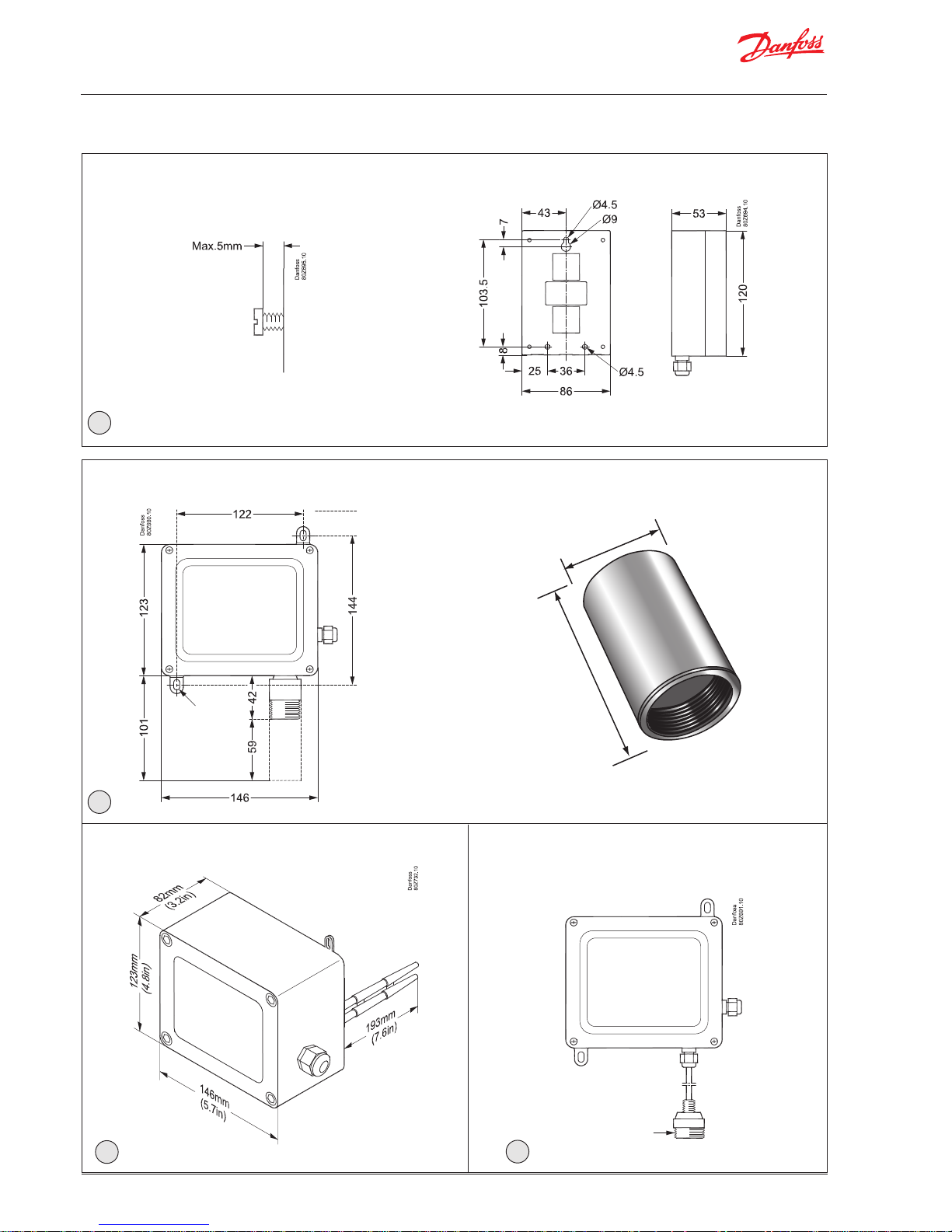
3. Dimensions and mounting
DGS Modbus Standard Housing
50 mm
75 mm
IP66 (with Splashguard)
Splashguard
IP66 Airflow Duct Mount Housing
mounting slots =
9mm long x 6mm
wide use 5mm 6mm screws
mounting
measurements
2
3
4
IP66 Housing with Remote Sensor Head
M42 thread
5
mounting slots =
9mm long x 6mm
wide use 5mm 6mm screws
Page 7
Installation and Operation Guide | DGS Modbus
RS8HJ102 | 7
© Danfoss | ADAP-KOOL® | 2016.12
4. Installation and Wiring
WARNING
Explosion hazard! Do not mount the DGS Modbus in
an area that may contain flammable liquids, vapors,
or aerosols. Operation of any electrical equipment
in such an environment constitutes a safety hazard.
CAUTION
The DGS contains sensitive electronic components
that can be easily damaged. Do not touch nor disturb any of these components.
NOTE The mounting location of the monitor should allow
it to be easily accessible for visual monitoring and
servicing.
NOTE The monitor must be connected by a marked, suit-
ably located and easily reached switch or circuitbreaker as means of disconnection
NOTE Connect monitor power and signaling terminals us-
ing wiring that complies with local electrical codes
or regulations for the intended application.
NOTE This instrument can be equipped with a semicon-
ductor sensor for the detection of refrigerant, combustible or VOC gases. Semiconductor sensors are
not gas specific and respond to a variety of other
gases including propane exhaust, cleaners, and solvents. Changes in temperature and humidity may
also affect the sensor’s performance.
4.1 Electrical connection and diagram
NOTE: The wiring is the same for the semi-conductor and infrared
models. The controller wiring is the same for all controllers.
There is a 5-minute power-up delay to allow the sensor to stabilise. Also see section 5.
Refer to Figure 1 for internal components and wiring.
Page 8
Installation and Operation Guide | DGS Modbus
© Danfoss | ADAP-KOOL® | 2016.12
8 | RS8HJ102 |
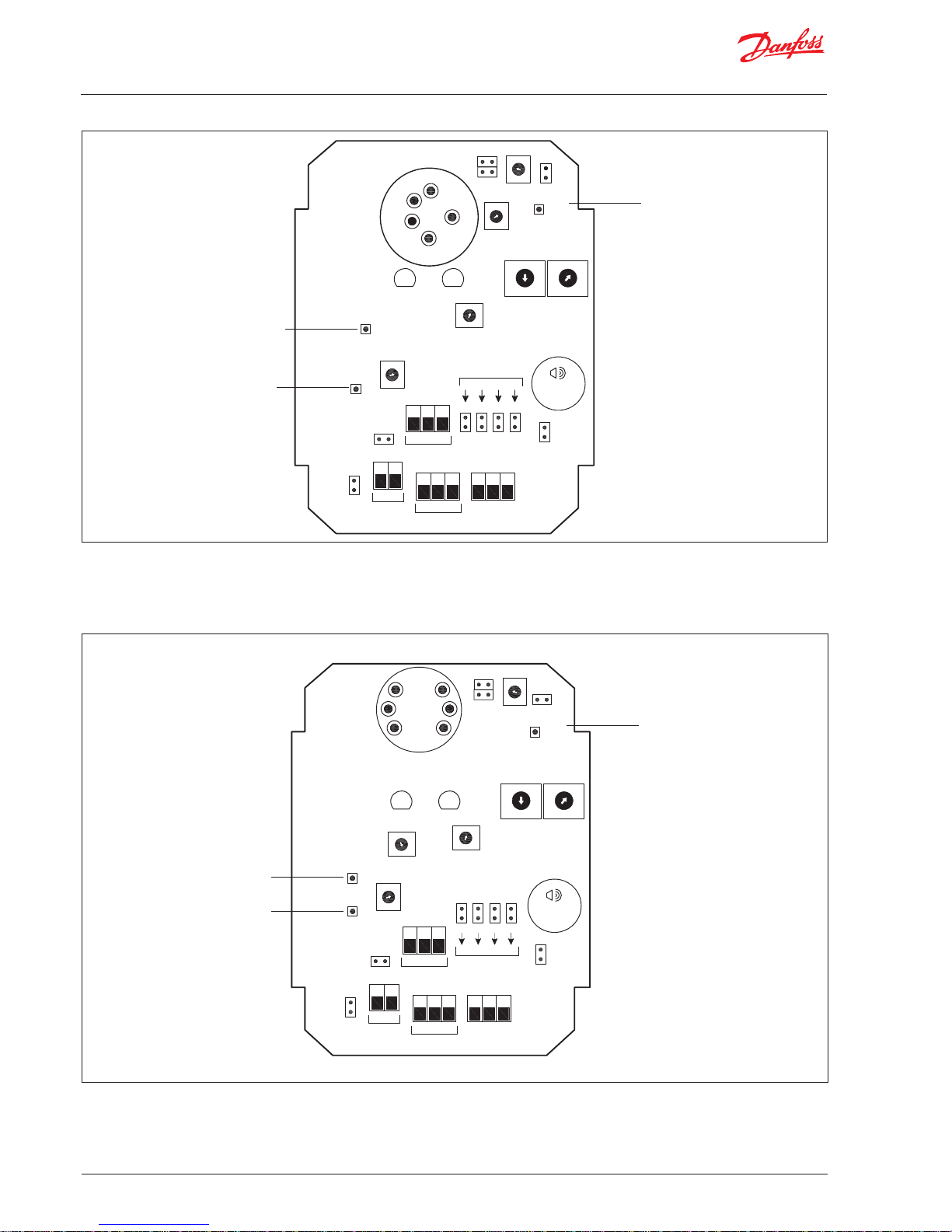
Figure 1a. Sensor Components (IR sensor)
Figure 1b. Sensor Components (SC Sensor)
Danfoss
80Z731.10
Alarm
P1
J4
Reset
TP1
(Alarm)
Delay
J5
J6
INFRARED
(IR) SENSOR
PC BOARD
GREEN
LED
RED
LED
P4
4-20mA
TP2
(Vs)
P3
Span
TP3
0V
J7 J8 J9 J10
CN4
0012
510510
G+
_
MODBUS
VOLTS
Audible
Alarm
J3
Addressing
AC Select
J1
CN1
CN2 CN3
DC
Select
0V V+
0V V I
Power
Supply
Output Signal
Relay
Out
N / O
COM
N / C
J2
Zero
P2
TX
+V
-V
RX
SIGNAL
SW1SW2
0
1
2
3
4
5
6
7
8
9
A
B
C
D
E
F
0
1
2
3
4
5
6
7
8
9
A
B
C
D
E
F
Danfoss
80Z730.10
Alarm
P1
J4
Reset
TP1
(Alarm)
Delay
J5
J6
SEMICONDUCTOR
(SC) SENSOR
PC BOARD
GREEN
LED
RED
LED
P4
P2
Zero
4-20mATP2
(Vs)
P3
Span
TP3
0V
J7 J8 J9 J10
CN4
0012
510510
G+
_
MODBUS
VOLTS
Audible
Alarm
J3
Addressing
AC Select
J1
CN1
CN2 CN3
DC
Select
0V V+
0V V I
Power
Supply
Output Signal
Relay
Out
N / O
COM
N / C
J2
SW1SW2
0
1
2
3
4
5
6
7
8
9
A
B
C
D
E
F
0
1
2
3
4
5
6
7
8
9
A
B
C
D
E
F
Sensor Voltage
Test Point
Sensor Voltage
Test Point
Board Ground
Plane Test Point
Board Ground
Plane Test Point
Audible Alarm and
Relay Set Point
Volage Test Point
Audible Alarm and
Relay Set Point
Volage Test Point
Page 9

Installation and Operation Guide | DGS Modbus
RS8HJ102 | 9
© Danfoss | ADAP-KOOL® | 2016.12
Item Description
Enclosure Access To open the IP41 Sensor enclosure: turn the cable gland ½ turn anticlockwise to loosen the internal
gland nut, depress the clip on top of the enclosure and open. Reverse to close.
With DGS-SC a retention strap fixates the sensor element during transportation. Remove it after opening the sensor enclosure by pulling the tap of the retention strap.
IP66 is open and closed with a Torx size TX25. It is supplies without any retention strap.
Power 12-24V AC/DC, connect at positions 0V and +V at connector block CN1.
• For AC: Jumper J1 is on, J2 is off.
• For DC: Jumper J1 is off, J2 is on. (Default factory setting is DC.)
Use 2 wires, typically 18 AWG (minimum).
Output Connect two wires to terminal block CN2 positions 0V and V or I for voltage or current, respectively.
• Connect 4-20mA at CN2 positions 0V and I
• Connect voltage output at CN2 positions 0V and V
Alarm relay
The digital alarm output signal is connected at connector block CN3
The alarm relay may be operated with or without fail safe function.
When the fail-safe function is enabled, the relay will give an alarm if the power is disconnected from the
DGS unit.
Most products are supplied with the fail-safe function disabled (see separate Datasheet for details).
It is possible via the Modbus interface to disable and enable the fail-safe function.
N/O Normally Open When operated without fail-safe, the ‘N/O’ and ‘COM’ terminals are used.
COM Common
N/C Normally Closed When operated with fail-safe, the ‘N/C’ and ‘COM’ terminals are used.
Modbus (RS-485) The Modbus connector is CN4.
G Ground Galvanically separated
- A (Rx/Tx) Modbus non-inverting signals
+ B (Tx/Rx) Modbus inverting signals
See section 4.4 for details on system integration.
Page 10

Installation and Operation Guide | DGS Modbus
© Danfoss | ADAP-KOOL® | 2016.12
10 | RS8HJ102 |
4.2 Jumper Configurations
Function Description
Input
Power
(J1, J2)
Decide whether the device will be powered (via CN1) with an AC
source or a DC source. See Figure 1 for jumper locations.
AC Power DC Power
Buzzer
(J3)
The unit has an internal audible alarm (see Figure 1). You can disable this alarm using jumper J3. The default setting is “enabled” in
compliance with EN378. See Figure 1 for details.
Reset
(J4)
This is a jumper used for changing the Modbus communication
speed. See section 4.4 for details on system integration.
Time Delay
(J5, J6)
A time delay is available to avoid false alarms from the buzzer and
relay. This is set with jumpers. The default delay is 0 minutes. The
max setting via jumpers is 10 minutes. See Figure 1 for jumper
locations.
Or the time delay is programmed via Modbus. See section 8.
A Modbus setting takes priority over the hardware setting (i.e.
they might be different).
DC Output
Selection
(J7-J10)
Decide which DC voltage output range is required for the DC output signal on connector CN2. See Figure 1 for jumper locations.
Page 11

Installation and Operation Guide | DGS Modbus
RS8HJ102 | 11
© Danfoss | ADAP-KOOL® | 2016.12
4.3 Adjusting the Alarm Setpoint
Function Description
1 Locate P1 and use it to adjust the set point at which the relay
activates.
2 Using a volt meter, monitor the output between test points
0V (negative) and ALARM (positive) until the correct setting is
reached. See formula below for example of how to calculate the
desired setpoint.
Voltage = Alarm Value ×
5 V____
Max Range
Voltage: The potentiometer is adjusted until this signal is measured between the test points
Alarm value: The ppm level at which the sensor must signal an
alarm on the relay and on Modbus
Max range: The maximum measurement range of the particular
DGS sensor
Example: For a sensor range of 0-1000 ppm, calculate the voltage
to set the alarm point at 100 ppm.
Voltage= 100 ppm ×
___5 V____
1000 ppm
= 0.5 V
So the alarm voltage setting is 0.5 Volts.
NOTE: The output changes when changing P1. It does not change
when changing the Modbus value.
The alarm setpoint may be changed physically via the potentiometer P1 (see below) or through the Modbus interface (see section
7).
If the Modbus setting takes a value different than ‘0’ (zero), the
Modbus setting takes priority.
As default the potentiometer setting takes priority (that is, the
default Modbus setting is ‘0’ (zero)
For all DGS gas detectors the process to adjust the alarm setpoint
via the potentiometer and test points ‘TP3 0V’ and ‘TP1 (Alarm) is
the same.
See Figure 1 for locations.
Alternatively this may be set via Modbus directly in ppm or % of
full scale.
See section 7 for details.
NOTE: A Modbus setting takes priority over the hardware setting.
If needed set the Modbus value to zero to re-activate the hardware setting.
For R449A the maximum allowed alarm setpoint is 500 ppm.
Page 12

Installation and Operation Guide | DGS Modbus
© Danfoss | ADAP-KOOL® | 2016.12
12 | RS8HJ102 |
Modbus connection Connector CN4 (labeled G, +, and -) is an RS-485 port for communicating with DGS Modbus gas detec-
tors in Modbus-RTU protocol.
Modbus Address To establish Modbus communication to Danfoss front end, configure the address using SW1 and SW2
and perform a network scan from the front end.
The Baud rate may need changing. It must be set to 19,200 baud when used with AK-SM 720/AK-SM
350 and when AK-SM 800 is configured in SLV-mode (see manual for AK-SM 800 for further details).
As default the AK-SM 800 communicate at the same baudrate as DGS.
The Hexadecimal Address Switches are used to set a unique address for the sensor. Valid addresses are
0-247.
The Modbus address can be set by the combined settings on the hexadecimal dial switches SW1 and
SW2. Addresses 0-15 are selectable with switch SW1 (the least significant portion of the address). SW2
scales the addresses by a factor of 16 (the most significant portion of the address).
ADDR = 16 x SW2 + SW1
Example: 40 = 16 x 2 + 8
SW1 = Least Significant Hex Character (0-F) = 0-15
SW2 = Most Significant Hex Character (0-F) = 0-15
ADDR SW2 SW1
1 0 1
2 0 2
3 0 3
: : :
9 0 9
10 0 A
11 0 B
: : :
15 0 F
16 1 0
: : :
246 6 F
247 7 F
See appendix B for complete list of all address'
NOTE: Addresses 0 and 248-255 (0x8F – 0xFF) are reserved.
Baud rate To choose a Baud rate, select the address and reset the gas detector by temporarily shorting jumper J4
(or by cycling the power off and on). After the Baud rate is set, the desired Modbus address (1-247) can
be selected by changing the switch settings with a power-cycle or reset operation afterwards.
Addresses 253 (0xFD) to 255 (0xFF) are reserved for setting the Modbus communications Baud rates.
ADDR S2 S1 BAUD RATE
254 F E 9,600
255 F F 19,200
253 F D 38,400 (Default)
NOTE: The default Baud rate is 38,400.
CAUTION
4.4 System integration
G Ground
(Galvanically separated)
+
Non-inverting
Modbus Signal (A)
TxD+/Rxd+
-
Inverting
Modbus Signal (B)
TxD-/Rxd-
Page 13

Installation and Operation Guide | DGS Modbus
RS8HJ102 | 13
© Danfoss | ADAP-KOOL® | 2016.12
5. Operation and Stabilisation
Stabilisation
On powering up it will sense for the presence of gas after an initial
warmup delay of 5 minutes. A Modbus service parameter is set
during the warm-up.
The typical time for various sensor types to stabilise is shown
below.
Sensor Type Stabilisation Time
Semiconductor (SC) 5 minutes
Infrared (IR) 2 minutes
On power up, semiconductor sensors output a signal voltage that
is over the + max scale, i.e., > 5V, and move towards zero as they
stabilise.
If sensors have been in long-term storage or the detectors have
been turned off for a long period, stabilisation is much slower.
However, within 1-2 hours sensors should have dropped below
the alarm level and be operational. You can monitor progress
exactly by monitoring the output (for example, 0-10V, or as otherwise configured). When the output settles around zero the sensor
is stabilised. In exceptional circumstances the process can take up
to 24 hours or more.
Alarm condition
In alarm condition: (e.g. high gas level)
• the green LED stays on
• the red LED will be on
• the buzzer operates (if it has not been disabled and after a
delay if this option has been selected)
• the relay output activates (after a delay if this option has been
selected)
• the "Limit alarm" and "Warning limit al" is activated as applicable (after a delay if this option has been selected)
• the voltage or current output changes proportional to gas
concentration
Fault condition
In fault condition: (e.g. sensing error)
• the green LED will be off
• the red LED will be on
• the applicable Modbus alarm is activated
• a voltage or current fault output will activate
2mA on the 4-20mA output
0.5V on the 1-5V output
1.0V on the 2-10V output
Manual control
It is possible to perform a manually control to verify the buzzer,
LED's and alarm relay, see Section 7.
Page 14

Installation and Operation Guide | DGS Modbus
© Danfoss | ADAP-KOOL® | 2016.12
14 | RS8HJ102 |
6. Functional Tests and Calibration
6.1 Introduction
To comply with the requirements of EN378 and the European
F-GAS regulation, sensors must be tested annually. However, local
regulations may specify the nature and frequency of this test.
NOTE: The DGS Modbus is calibrated at the factory.
After installation, a zero adjustment may be required to
DGS-SC due to differences in environmental conditions.
DGS-IR should never need any adjustment after installation.
CAUTION: Check local regulations on calibration or testing requirements.
CAUTION: The DGS Modbus contains sensitive electronic components that can be easily damaged. Do not touch nor disturb any of
these components while lid is removed and when replacing it.
IMPORTANT: If the DGS-SC is exposed to a large leak it should be
tested to ensure correct functionality by electrically resetting the
zero setting and carrying out a bump test. See procedures below.
This does not apply to DGS-IR.
IMPORTANT: Danfoss recommends annual checks and gas
calibration. Danfoss also recommends sensor replacement every
3 years or as required. Calibration frequency may be extended
based on application, but should never exceed 2 years.
IMPORTANT: In applications where life safety is critical, calibration
should be done quarterly (every 3 months) or on a more frequent
basis. Danfoss is not responsible for setting safety practices and
policies. Safe work procedures including calibration policies are
best determined by company policy, industry standards, and local
codes.
IMPORTANT: Failure to test or calibrate the unit in accordance
with applicable instructions and with industry guidelines may
result in serious injury or death. The manufacturer is not liable for
any loss, injury, or damage arising from improper testing, incorrect
calibration, or inappropriate use of the unit.
IMPORTANT: Before testing the sensors on-site, the DGS Modbus
must have been powered up and allowed to stabilise. See section
5.
IMPORTANT: The testing and/or calibration of the unit must be
carried out by a suitably qualified technician, and must be done:
• in accordance with this manual
• in compliance with locally applicable guidelines and regulations.
Suitably qualified operators of the unit should be aware of the
regulations and standards set down by the industry/country for
the testing or calibration of this unit. This manual is only intended
as a guide and, insofar as permitted by law, the manufacturer accepts no responsibility for the calibration, testing, or operation of
this unit.
The frequency and nature of testing or calibration may be determined by local regulation or standards.
EN378 and the F-GAS Regulation require an annual check in accordance with the manufacturer’s recommendation.
There are two concepts that need to be differentiated:
• bump test
• calibration.
Bump Test:
Exposing the sensor to a gas and observing its response to the
gas. The objective is to establish if the sensor is reacting to the gas
and all the sensor outputs are working correctly. There are two
types of bump test.
Quantified: A known concentration of gas is used.
Non-Quantified: A gas of unknown concentration is used.
Calibration:
Exposing the sensor to a calibration gas, setting the “zero” or
standby voltage to the span/range, and checking/adjusting all
the outputs, to ensure that they are activated at the specified gas
concentration.
CAUTION: Before you carry out the test or calibration:
• Advise occupants, plant operators, and supervisors.
• Check if the DGS Modbus is connected to external systems
such as sprinkler systems, plant shut down, external sirens and
beacons, ventilation, etc. and disconnect as instructed by the
customer.
• Deactivate alarm delays if selected at JP5, JP6 as per Figure 1 or
via Modbus. See section 7.
• For bump test or calibration the DGS Modbus should be powered up overnight. The instrument should be fully stabilised per
Section 5.
Page 15

Installation and Operation Guide | DGS Modbus
RS8HJ102 | 15
© Danfoss | ADAP-KOOL® | 2016.12
6.2 Bump Testing
After installation, the units should be bump tested. Expose the
sensors to test gas (R134A, CO2, etc.). The gas should put the
system into alarm and light the red LED. The delay prevents the
audible alarm from sounding, the relay from switching and the
alarm from activating on Modbus.
With a bump test you can see the functions of the sensor - the red
LED will light, the relay and audible alarm will function, and the
output (0 - 10V, for example) will show the gas level.
Ideally bump tests are conducted on site in a clean air atmosphere.
NOTE: Prior to carrying out a bump test, check and adjust the zero
setting as described in the Calibration section.
NOTE: Procedures for bump test and calibration vary depending
on the sensor technology used and the gas in question. The DGS
Modbus is available in two sensor versions: Semiconductor (SC)
and Infrared (IR).
NOTE: Do not pressurise the sensor.
NOTE: For semiconductor sensors, you MUST use calibration gas
in a balance of air (not N2).
IMPORTANT: After a semiconductor sensor is exposed to a substantial gas leak, the sensor should be zero calibrated and bump
tested and replaced if necessary.
NOTE: To test the audible alarm and/or relay function, check the
delay is set at zero and expose to gas. You can mute the audible
alarm by removing jumper J3.
Step Bump Testing Using Calibration Gas Cylinders
1 Remove the enclosure lid of the gas detector (not in an
exhaust area).
2 Connect a voltmeter to monitor sensor response. Moni-
tor response (0-5V) between pins 0V (TP3) and Vs (TP2).
3 Expose the sensor to gas from the cylinder. Use a plastic
hose/hood to direct gas to the sensor head. A response
of above 80% is acceptable.
NOTE: Gas ampoules are not valid for calibration or accuracy
checks of the sensor. These require actual gas calibration, not
bump testing with ampoules.
Calibration Kit
Flow
Regulator
Typical Flow
0.3L/Min
Outlet 5/8’’
18 UNF
(C10)
Flexible nonabsorbant
tubing
Vented
Calibration
Hood
Cylinder
360mm high x 88mm diameter
440mm high with flow regulator
110L capacity of calibration gas
Weight 1.4 kg
Figure 6. Gas Cylinder and Test Hardware
Figure 7. Gas Ampoules for Bump Testing
Gas ampoules are convenient and inexpensive alternatives to
using gas cylinders for bump testing.
Sensor
adapter
M35 adapter
Gas ampoules
Test beaker
(M42 Thread)
Page 16

Installation and Operation Guide | DGS Modbus
© Danfoss | ADAP-KOOL® | 2016.12
16 | RS8HJ102 |
Step Bump Testing Using Gas Ampoules
1 Make sure that both the ampoules and the calibration
beaker are clean and dry.
2 Unscrew the beaker hold screw and place the ampoule
so that it sits in the base of the beaker (see Figure 7).
3 Tighten wing-nut screw onto the ampoule without
breaking it.
4 Remove the enclosure lid of the gas detector.
5 Connect a voltmeter to monitor sensor response. Moni-
tor response (0-5V) between pins 0V (TP3) and Vs (TP2).
6 Place the beaker over the sensor head using the multi
sensor adaptor to fit the sensor, or, if an Exd, IP66 or
Remote sensor head version, screw the beaker on the
remote sensor head M42 thread or M35 thread adaptor.
It should be as tight fitting as possible to allow maximum gas exposure.
7 Tighten the wing-nut screw onto the ampoule until it
shatters allowing the gas to diffuse in the beaker. It
should be left in place for approximately 5 min.
8 The voltage output will increase. This confirms that the
sensor is responding. A response equivalent to at least
50% of the test gas (typical) will confirm that the system
is in order.
9 Remove the beaker from the sensor. Carefully remove
any ampoule remains from the gas detector and beaker.
6.3 Calibration Overview
There are two adjustments required: zero and span. They are
monitored at testpoint TP2 and TP3 using a 0-5V scale. See fig. 1.
If the sensor range is 0-1000 ppm, then 5V=1000 ppm.
Tools required:
• Gas cylinder with the appropriate gas and concentration
• Calibration kit
• A voltmeter (crocodile clips recommended)
• Screwdriver (depending on housing).
Danfoss offers calibration gasses and a kit that consists of a flow
regulation valve with flexible non-absorbent tubing and vented
calibration hood. (see fig. 6).
NOTE: For improved accuracy and response, the instrument
should be zeroed and calibrated in the environment in which it is
being installed.
6.4 Calculating Calibration Voltage
Sensor outputs are linear. As long as you have a gas cylinder of
known concentration you can calibrate to any desired range*.
However, for maximum accuracy calibrate with a gas close to the
alarm set point.
Example: For a sensor range of 0-1000 ppm and a cylinder of the
target gas at 800 ppm:
Voltage = Target Gas Value ×
_____5 V_____
Sensor Range
Voltage = 800 ppm ×
___5 V____ _
1000 ppm
= 4 V
So the output voltage signal should be adjusted to 4V.
*For R449A only: This gas is nonlinear above 500ppm. Calibration must be done with
a 500 ppm gas. Any readings above 500ppm must be regarded as in-valid. 500ppm is
also the maximum allowed alarm threshold for this gas.
6.5 Calibrating Semiconductor (SC) Sensors
Step Calibrating Semiconductor (SC) Sensors
1 Locate P2 which is used to adjust the zero point.
2 Monitor the output between 0V (TP3) and Vs (TP2).
3 Expose sensor to zero air until output is stable (typically
3-5 minutes).
4 Adjust P2 until the voltmeter reads a slightly positive
value (0.01 V is acceptable).
5 Locate P3 which is used to calibrate the range (span) of
the sensor.
6 Expose the sensor to calibration gas and allow to stabi-
lise (typically 3-5 minutes).
7 Adjust P3 until the voltmeter equals the voltage calcu-
lated in section 6.4
NOTE: For semiconductor sensors, you MUST use calibration gas
in a balance of air (not N2).
6.6 Calibrating Infrared (IR) Sensors
Step Calibrating Infrared (IR) Sensors
1 Locate P2 which is used to adjust the zero point.
2 Monitor the output between 0V (TP3) and Vs (TP2).
3 Expose the sensor to nitrogen or zero air until output is
stable (typically 3-5 minutes).
4 Adjust P2 until the voltmeter reads 0 V or slightly posi-
tive (0.01 V is acceptable).
5 Locate P3 which is used to calibrate the range (span) of
the sensor.
6 Using the appropriate calibration hood for the sensor,
expose the sensor to calibration gas and allow to stabilise (typically 3-5 minutes).
7 Adjust P3 until the voltmeter equals the voltage calcu-
lated in section 6.4
6.7 Calibration of alarm setpoint
See section 4.3
6.9 Issue Test certificate
See example in appendix C
6.8 Calibration of 4-20mA output
For improved accuracy of the 4-20mA output it is possible to zero
adjust this separately. This is done by adjusting the potentiometer
P4 until the output corresponds to the gas concentration:
Current = 4mA + gas concentration ×
_____16 mA____
Sensor Range
Example for a sensor range of 0-1000ppm and a gas concentration
of 800ppm:
Current = 4mA + 800 ppm ×
___16mA____ _
1000 ppm
= 16.8mA
Page 17

Installation and Operation Guide | DGS Modbus
RS8HJ102 | 17
© Danfoss | ADAP-KOOL® | 2016.12
To install the DGS unit on the network, first set the network address (see section 4.4 of this manual). Following this, the DGS unit
can be installed on the network and configured in the Front End.
(see Front End manual for specific details)
For communication speeds other than the default 38.4k, please
refer to section 4.4 of this manual and the manual of the system
manager.
7. Installation
Survey of functions
Function Parameter by operation via data
communication
Gas level
Actual gas level in %
The actual gas level is displayed here as a percentage of the full scale ppm. The full scale ppm
can be viewed in the “Service” group.
Example: If the full scale value is 1000ppm and the sensor is measuring 400ppm, the value is
40%
Gas level %
(shown in all menu displays)
Actual gas level in ppm
The actual gas level is displayed here as a ppm value.
Gas level ppm
(shown in all menu displays)
Alarms Alarm settings
As default the potentiometer in the DGS unit defines the alarm limit (see section 4.3) and the
warning function is disabled.
By changing the value of the “Alarm Limit” parameter, the alarm parameter defines the alarm
limit and the Warning function can be enabled.
Changing the alarm limit parameter to zero will enable the potentiometer alarm setting and
disable the warning function. The potentiometer value is read back to the Alarm Limit parameter and presented (zero is overwritten).
It is not possible to adjust the alarm limit below the actual warning limit.
It is not possible to adjust the warning limit above the actual alarm limit.
If this is attempted, the value is considered invalid and ignored.
Critical alarm indication
Common indication of alarms (any alarms active excl. warnings)
The indication is given as soon as the alarm condition is present regardless of any alarm time
delays
0 = No active alarm(s)
1 = Alarm(s) active
GD alarm
General alarm incication
Common indication of any alarms incl. warnings
The indication is given as soon as the alarm condition is present regardless of any alarm time
delays
0 = No active alarm(s) or warning(s)
1 = Alarm(s) or warning(s) active
Common errors
Alarm limit in %
The alarm limit can be set as a percentage of full scale ppm. The full scale ppm can be viewed
in the “Service” group.
Example: If the full scale value is 1000ppm and the sensor should give alarm at 500ppm, the
value is entered as 50%
Alarm limit %
Alarm limit in ppm
The alarm limit is entered here as a ppm value.
Alarm limit ppm
Time delay for level alarms
High alarm delay in minutes.
If set to 0, the hardware jumper configuration is used. This means that the hardware configured
delay will be shown (zero is overwritten).
If set to a value above zero, this value is used instead of the hardware jumper configuration.
The value is used both as delay for limit alarm and warning.
Alarm delay
Reset alarm in DGS unit
Will mute the buzzer and reset the alarm relay. The alarm remains active (LED and Modbus)
until the alarm condition disappears.
Reset alarm
SW 1.1x
Page 18

Installation and Operation Guide | DGS Modbus
© Danfoss | ADAP-KOOL® | 2016.12
18 | RS8HJ102 |
Duration of Reset alarm
Maximum duration of alarm reset before automatic re-enable of external indicators (mute
timeout in minutes) a value of 0 disables ability to mute alarm.
The duration time is set in minutes
Reset alarm time
Warning limit in %
The warning limit can be set as a percentage of full scale ppm. The full scale ppm can be
viewed in the “Service” group.
Example: If the full scale value is 1000ppm and the sensor should give alarm at 200ppm, the
value is entered as 20%
Warning limit %
Warning limit in ppm
The warning limit is entered here as a ppm value.
Warning lim. ppm
Enabling of Warning alarm
It is possible to enable a warning alarm to give an early indication of a potential high alarm
limit.
Enables warning alarm when the Warning limit is exceeded
Warning Enable
Service Service
Refrigerant type
Read out of refrigerant (Gas) used for the for the DGS is used for
Refrigerant
Gas Full scale in ppm
The full scale ppm value is displayed here
Fullscale ppm
Hours since last calibration
Keeps a count of the number of hours the sensor is powered on. The value is incremented
every hour and after one year the register will exceed 8760 hours and the Calibrate Sensor
alarm is set to indicate that the detector requires testing. The “Reset Cal” is used to reset both
the alarm and the “Burning Hours” timer.
Burning hours
Status of the sensor warm up period
Depending on the sensing technology of the actual DGS unit, it will have a warm-up period of
up to 5 minutes until the measurements are accurate
0 =Ready
1 = Warming Up
Startup flag
Reset calibration counter and warning
Clears calibration due warning and resets the burning hours parameter to zero
0 = Calibration valid
1 = Calibration due
Reset cal
Alarm relay Failsafe configuration
The alarm relay function can be configured to give an alarm when the DGS unit is powered off.
0 = Not failsafe
1 = Failsafe
Relay failsafe
Enable Manual control
In a service situation it is possible to set the DGS unit in a manual control mode to validate the
installation.
As a pre-caution, the DGS unit automatically changes back from manual control to normal
operation after 10 minutes
Maunal Control
Status of the alarm relay
Displays the status of the alarm relay
Can be operated in Manual Control mode
0 = No alarm signal
1 = alarm signal
Alarm Relay
Status of the buzzer
Displays the status of the buzzer.
Can be operated in Manual Control mode
0 = inactive
1 = active
Sounder
Status of the red LED
Displays the status of the red LED (unit in alarm condition).
Can be operated in Manual Control mode
0 = off
1 = on
Red LED
Status of the green LED
Displays the status of the green LED (unit powered ON).
Can be operated in Manual Control mode
0 = off
1 = on
Green LED
Page 19

Installation and Operation Guide | DGS Modbus
RS8HJ102 | 19
© Danfoss | ADAP-KOOL® | 2016.12
Alarms
When an alarm condition becomes present, the red LED is lid immediately.
If a delay is configured for a given alarm, the buzzer, alarm relay and Modbus alarm are set active after the delay has expired.
Critical alarm for high gas level Limit alarm
The gas level exceeds the full-scale value. Likely the sensor element needs replacing Sensor saturated
The signal from the sensor is missing (sensor element defect or removed) Sensor out
DGS unit due for calibration as it has been operating for 1 year or more Calibrate sensor
Warning alarm for high gas level Warning limit al.
Menu Survey
Function Min Max Factory Unit AKM name
Gas level
Actual gas level in % 0.0 100.0 0.0 % Gas level %
Actual gas level in ppm (OBS note 1)
0
FS2
0 ppm Gas level ppm
Alarms Alarm settings
Common indication of alarms (any alarms active excl. warnings)
0 = No active alarm(s)
1 = Alarm(s) active
0 1 0 - GD alarm
Common indication of both alarms incl. warnings
0 = No active alarm(s) or warning(s)
1 = Alarm(s) or warning(s)) active
0 1 0 - Common errors
Alarm limit in % 0.0 100.0 0.0 % Alarm limit %
Alarm limit in ppm 0
FS2
0 ppm Alarm limit ppm
High alarm delay in minutes, if set to 0 hardware jumper configuration is used (hardware configured delay will be shown).
If set to value, software alarm delay is used.
0 10 0 min. Alarm delay
When set to 1, the alarm relay and sounder are reset to no
alarm indication (mute a connected indicator). When the
alarm is reset or the timeout duration is exceeded, the value
is reset to 0.
OBS: The alarm condition is not reset only the relay indication
is reset. Used to mute an external alert (audible/visible)
0 = Alarm outputs not muted
1 = Alarm outputs muted
0 1 0 - Reset alarm
Maximum duration of alarm reset before automatic re-enable of external indicators (mute timeout in minutes) a value
of 0 disables ability to mute alarm.
0 59 0 min Reset alarm time
Warning limit in % 0.0 100.0 0.0 % Warning limit %
Warning limit in ppm 0
FS2
0 ppm Warning lim. ppm
Enables warning alarm when Warning limit exceeded 0 1 0 min. Warning Enable
1
The communication system can only handle integer values in the range -32000 to 32000 and decimal values in the range -3200.0 to 3200.0.
2
Value equals fullscale range of specific product
Page 20

Installation and Operation Guide | DGS Modbus
© Danfoss | ADAP-KOOL® | 2016.12
20 | RS8HJ102 |
Service
Read out of refrigerant (Gas) for the DGS is used for
Value according to "Danfoss standard list".
1 42 N - Refrigerant
Gas Full scale in ppm 0 32000 0 ppm Fullscale ppm
Hours since last calibration 0 32000 0 hours Burning hours
Status of the sensor warm up period
0 =Ready
1 = Warming Up
0 1 0 - Startup flag
When cleared, clears calibration due alarm and resets the
burning hours parameter
0 = Calibration valid
1 = Calibration due
0 1 0 - Reset cal
Failsafe operation of the Relay
0 = Not failsafe
1 = Failsafe
0 1 0 - Relay failsafe
Enables Manual control of Relays.
Automatically falls back to Off after 10 min.
0 1 0 - Maunal Control
Status of the high alarm relay
0 = No alarm signal
1 = alarm signal
0 1 0 - Alarm Relay
Status of the buzzer
0 = inactive
1 = active
0 1 0 - Sounder
Status of the red LED
0 = off
1 = on
0 1 0 - Red LED
Status of the green LED
0 = off
1 = on
0 1 0 - Green LED
Alarms
Limit alarm
0 = Alarm not active
1 = Alarm, gas limit exceeded
0 1 0 - Limit alarm
Sensor saturated
0 = OK
1 = Fault. Out of range under test
0 1 0 - Sensor saturated
Sensor out
0 = OK, sensor in place
1 = Fault, Sensor out or removed
0 1 0 - Sensor out
Calibrate sensor
0 = OP, Sensor not due for calibration
1 = Warning, Due for calibration
0 1 0 - Calibrate sensor
Warning limit alarm
0 = OK, Gas level below warning level
1 = Warning, Gas level above warning level and delay expired
0 1 0 - Warning limit al.
Page 21

Installation and Operation Guide | DGS Modbus
RS8HJ102 | 21
© Danfoss | ADAP-KOOL® | 2016.12
8. Accessories
Accessories for calibration
Code no
Calibration kit
(excl. gas)
080Z2296
110l cylinder with
10.000 ppm CO
2
080Z2297
110l cylinder with
100% N
2
080Z2298
110l cylinder with
5.000 ppm CO
2
080Z2299
Page 22

Installation and Operation Guide | DGS Modbus
© Danfoss | ADAP-KOOL® | 2016.12
22 | RS8HJ102 |
9. Troubleshooting
Symptom Possible Cause(s)
Green and Red light off • Check power supply. Check
wiring.
• DGS Modbus was possibly
damaged in transit. Check
by installing another DGS
Modbus to confirm the fault.
Red light on, green led off
(indicates a fault)
• Sensor may be disconnected
from printed circuit board.
Check to see sensor is
properly inserted into board.
• The sensor has been
damaged or has reached the
end of life and needs to be
exchanged. Contact Danfoss
for instructions and support
• The zero-adjustment has
been reduced to achieve
a zero-measurement in
an environment with gas,
typically CO2. Do a zeroadjustment with a zero-gas
and a re-calibration.
Alarms in the absence of a leak • If you experience alarms in
the absence of a leak, try
setting an alarm delay.
• Perform a bump test to
ensure proper operation.
The zero-measurement drifts The DGS-SC sensor technology
is sensitive to the environment
(temperature, moist, cleaning
agents, gas' from trucks, etc).
All ppm measurements below
75ppm should be disregarded,
i.e. no zero-adjustment made.
When changing potentiometer P1, the test point
measurement is changing but
the active alarm point is not
changing
Any alarm limit configured via
Modbus takes priority over
the setpoint set electrically
via potentiometer P1. To
re-enable the setpoint
adjustment via P1, set the
Modbus parameter to '0'
(zero).
Page 23

Installation and Operation Guide | DGS Modbus
RS8HJ102 | 23
© Danfoss | ADAP-KOOL® | 2016.12
Supported Air flows and Duct Sizes for the Duct Mount Housing
Units Duct Sizes
inches 12 x 12 12 x 24 18 x 18 24 x 24 24 round
feet 1 x 1 1 x 2 1.5 x 1.5 2 x 2 3.14 x 1 x 1
area (ft2) 1 2 2.25 4 3.14
CFM* Ft/min (Based on CFM* and Duct Size)
2800 2800 n/a n/a n/a n/a
3000 3000 n/a n/a n/a n/a
3400 3400 n/a n/a n/a n/a
3800 3800 n/a n/a n/a n/a
4000 4000 n/a n/a n/a n/a
4400 4400 n/a n/a n/a n/a
4800 4800 n/a n/a n/a n/a
5000 5000 2500 n/a n/a n/a
5400 5400 2700 n/a n/a n/a
5800 5800 2900 2578 n/a n/a
6000 6000 3000 2667 n/a n/a
6400 6400 3200 2844 n/a n/a
6800 6800 3400 3022 n/a n/a
7000 7000 3500 3111 n/a n/a
7400 7400 3700 3289 n/a n/a
7800 7800 3900 3467 n/a n/a
8000 8000 4000 3556 n/a 2548
8400 8400 4200 3733 n/a 2675
8800 8800 4400 3911 n/a 2803
9000 9000 4500 4000 n/a 2866
9400 9400 4700 4178 n/a 2994
9800 9800 4900 4356 n/a 3121
10000 10000 5000 4444 2500 3185
Appendix A
* CFM = Cubic Foot per Minute
Page 24

Installation and Operation Guide | DGS Modbus
© Danfoss | ADAP-KOOL® | 2016.12
24 | RS8HJ102 |
Appendix B
Ad. SW1 SW2
1 1 0
2 2 0
3 3 0
4 4 0
5 5 0
6 6 0
7 7 0
8 8 0
9 9 0
10 A 0
11 B 0
12 C 0
13 D 0
14 E 0
15 F 0
16 0 1
17 1 1
18 2 1
19 3 1
20 4 1
Ad. SW1 SW2
21 5 1
22 6 1
23 7 1
24 8 1
25 9 1
26 A 1
27 B 1
28 C 1
29 D 1
30 E 1
31 F 1
32 0 2
33 1 2
34 2 2
35 3 2
36 4 2
37 5 2
38 6 2
39 7 2
40 8 2
Ad. SW1 SW2
41 9 2
42 A 2
43 B 2
44 C 2
45 D 2
46 E 2
47 F 2
48 0 3
49 1 3
50 2 3
51 3 3
52 4 3
53 5 3
54 6 3
55 7 3
56 8 3
57 9 3
58 A 3
59 B 3
60 C 3
Ad. SW1 SW2
61 D 3
62 E 3
63 F 3
64 0 4
65 1 4
66 2 4
67 3 4
68 4 4
69 5 4
70 6 4
71 7 4
72 8 4
73 9 4
74 A 4
75 B 4
76 C 4
77 D 4
78 E 4
79 F 4
80 0 5
Ad. SW1 SW2
81 1 5
82 2 5
83 3 5
84 4 5
85 5 5
86 6 5
87 7 5
88 8 5
89 9 5
90 A 5
91 B 5
92 C 5
93 D 5
94 E 5
95 F 5
96 0 6
97 1 6
98 2 6
99 3 6
100 4 6
Ad. SW1 SW2
101 5 6
102 6 6
103 7 6
104 8 6
105 9 6
106 A 6
107 B 6
108 C 6
109 D 6
110 E 6
111 F 6
112 0 7
113 1 7
114 2 7
115 3 7
116 4 7
117 5 7
118 6 7
119 7 7
120 8 7
DGS Modbus addressing 1-120
Page 25

Installation and Operation Guide | DGS Modbus
RS8HJ102 | 25
© Danfoss | ADAP-KOOL® | 2016.12
DGS Test Certificate (Example)
(Download original from our web site www.danfoss.com. Use in Conjunction with the Danfoss Check Calibration Procedure)
Product Description: DGS Serial Number: 12345
Date of First Calibration: (see Rating Label) 25/10/05 Date of Last Calibration: 25/10/05
Type/Range of Test Gas: Cylinder 1000ppm R404a, batch no xxxx
1. Carry out Bump Test (set delay to zero)
2. On site Gas Calibration (2 Yearly)
Power (Green LED) ...........................................................
Visual Alarm (Red LED) ...................................................
Sounder Operating ..........................................................
Relay Operating ................................................................
Remote Systems if connected to relay .....................
Check Analogue Output in Use, e.g.
0 – 10V ..................................................................................
System Passed ...................................................................
If system failed, carry out a gas calibration. See below.
System Passed ...................................................................
If the DGS did not respond correctly and could not be recalibrated due to age, exposure to gas etc, then either the DGS or
the sensor element should be replaced (and recalibrated) and the test process repeated.
System Passed ...................................................................
We hereby certify that the above specified test procedure has been performed and the DGS is performing as specified.
Test Performed by ________________________________________________ ______________________________
Signature Date
Appendix C
Page 26

Installation and Operation Guide | DGS Modbus
© Danfoss | ADAP-KOOL® | 2016.12
26 | RS8HJ102 |
ADAP-KOOL®
Danfoss can accept no responsibility for possible errors in catalogues, brochures and other printed material. Danfoss reserves the right to alter its products without notice. This also applies to products
already on order provided that such alternations can be made without subsequential changes being necessary in specifications already agreed.
All trademarks in this material are property of the respecitve companies. Danfoss and Danfoss logotype are trademarks of Danfoss A/S. All rights reserved.
 Loading...