


User Guide
Danfoss Gas Sensor
Type DGS
danfoss.com

User Guide | Danfoss Gas sensor, type DGS
Contents
1. Intended use ...................................................................................................................................3
2. Introduction ....................................................................................................................................3
3. Installation and maintenance .......................................................................................................3
3.1 Technician use only! ............................................................................................................................................ 3
3.2 Regular Test .......................................................................................................................................................... 3
3.3 Location .................................................................................................................................................................. 3
3.4 Dimensions and appearance ............................................................................................................................ 4
3.5 Cable gland opening ........................................................................................................................................... 4
3.6 Board pinout ......................................................................................................................................................... 4
3.7 Installation instructions ..................................................................................................................................... 5
3.8 Installation Test .................................................................................................................................................... 6
3.9 Troubleshooting ................................................................................................................................................... 7
3.10 Power Conditions and Shielding Conceptions ..............................................................................................7
4. Operation ......................................................................................................................................9
4.1 Function of the keys and LEDs on the keypad .............................................................................................10
4.2 Setting / changing of parameters and set points .......................................................................................10
4.3 Code levels ...........................................................................................................................................................10
5. Menu overview .............................................................................................................................11
5.1 Error status...........................................................................................................................................................12
5.2 Alarm Status ........................................................................................................................................................ 13
5.3 Relay Status ......................................................................................................................................................... 13
5.4 Menu Measuring Values ...................................................................................................................................13
5.5 Display Parameters ............................................................................................................................................14
5.5.1 Software Version ................................................................................................................................... 14
5.5.2 Language ................................................................................................................................................ 14
5.5.3 LCD Function Check .............................................................................................................................14
5.6 Alarm Reset Settings .........................................................................................................................................14
5.6.1 Relay Reset .............................................................................................................................................. 14
5.6.2 Alarm reset duration ............................................................................................................................ 15
5.7 Alarm Settings ....................................................................................................................................................15
5.7.1 Room mode ............................................................................................................................................ 15
5.7.2 Alarm limits ............................................................................................................................................ 15
5.7.3 Alarm relay ............................................................................................................................................. 15
5.8 AO Settings ..........................................................................................................................................................16
5.9 Operating Data ..................................................................................................................................................17
5.10 Calibration ........................................................................................................................................................... 18
5.10.1 Zero calibration ..................................................................................................................................... 19
5.10.2 Gain calibration ....................................................................................................................................20
5.10.3 Zero point calibration of analogue output .....................................................................................21
5.11 Addressing ........................................................................................................................................................... 21
6. MODBUS menu survey .................................................................................................................22
7. Ordering ....................................................................................................................................24
2 | BC291049702513en-000201 © Danfoss | Climate Solutions | 2022.01

User Guide | Danfoss Gas sensor, type DGS
1. Intended use This document has the intent to provide the guidelines to avoid possible damages deriving from
overvoltage and other possible issues resulting from the connection to the DGS power supply and
the serial communication network. Moreover it provides the operations executed via handheld
Service Tool. The display of the hand-held Service Tool and the MODBUS interface for integration with
Building Management Systems is used as interface for operation, commissioning and calibration of
the DGS gas detection unit.
2. Introduction
3. Installation and
maintenance
3.1 Technician use only!
For what concerns display devices, this user guide contains the maximum possible functionality.
Depending on the DGS type some features described here are not applicable and therefore the menu
items may be hidden.
Some special features are available via the hand-held Service Tool interface only (not via MODBUS).
This includes the calibration routine and certain properties of the sensor head.
This unit must be installed by a suitably qualified
technician who will install this unit in accordance
with these instructions and the standards set
down in their particular industry/country.
Suitably qualified operators of the unit should be
aware of the regulations and standards set down
by their industry/country for the operation of this
unit.
These notes are only intended as a guide, and
the manufacturer bears no responsibility for the
installation or operation of this unit.
Please observe that DGS works as a safety
device securing a reaction to a detected high
gas concentration. If a leakage occurs, the
DGS will provide alarm functions, but it will
not solve or take care of the leakage root
cause itself.
Failure to install and operate the unit in
accordance with these instructions and with
industry guidelines may cause serious injury
including death, and the manufacturer will not
be held responsible in this regard.
It is the installer’s responsibility to adequately
ensure that the equipment is installed correctly
and set up according to the environment and the
application in which the products are being used.
3.2 Regular Test
3.3 Location
To maintain product performance and comply
with the local requirements, the DGS must be
tested regularly.
DGSs are provided with a test button that may be
activated to validate the alarm reactions.
Additionally, the sensors must be tested by either
bump test or calibration.
Danfoss recommends the following minimum
calibration intervals:
DGS-IR: 60 months
DGS-SC: 12 months
DGS-PE: 6 months
For all gases heavier than air, Danfoss
recommends placing the sensor head app. 30 cm
(12”) above the floor and, if possible, in the air
flow. All gases measured with these DGS sensors
are heavier than air: HFC grp 1, HFC grp 2, HFC
grp 3, CO and propane.
For further details on Test and Location please see
the Danfoss Application Guide: “Gas detection in
refrigeration systems”.
With DGS-IR it is recommended to do an annual
bump test in years without calibration.
Check local regulations on calibration or testing
requirements.
For propane: after exposure to a substantial gas
leak, the sensor should be checked by bump test
or calibration and replaced if necessary.
© Danfoss | Climate Solutions | 2022.01 BC291049702513en-000201 | 3

Danfoss
1
C
User Guide | Danfoss Gas sensor, type DGS
3.4 Dimensions and
appearance
Fig. 1
3.5 Cable gland opening
3.6 Board pinout
Fig. 2
Hole punching for cable gland:
1. Select the location for the safest
cable entry
2. Use a sharp screwdriver and a
small hammer
3. Place the screwdriver and
hammer with precision while
moving the screwdriver within
a small area until the plastic is
penetrated.
Fig. 3
5
open: 0-20mA
closed: 0-10V
x8
JP5
4
not used
2
1
x1
LED
Yellow/Green/Red
GND
AO_01
DI_01
S&H supply
Continue precision punching with
small movements until the round
piece can be pulled out with your
fingers.
Remove potential burrs and secure
flat surfaces.
Install the cable gland according to
the enclosed guide.
WARNING: be very careful not to damage the internal
board components with the screwdriver.
1
Rel. 3
2
x6
x5
Ackn.-/Test
button
(critical)
3
Rel. 1
1
(warning)
2
3
x4
Danfoss
80Z790.1
4
BMODBUS
3
A+
2
24 V AC/D
+
1
148H126_01-2018
JP4
x2
Sensor 2
Tool
x9
Sensor 1
x3
JP3
JP2
JP1
not used
B&L
open: 19200 Baud
closed: 38400 Baud
Note: For what concern the power supply, please refer to chapter 3.10 Power Conditions and Shielding
Conceptions.
A Class II power supply is recommended
4 | BC291049702513en-000201 © Danfoss | Climate Solutions | 2022.01

User Guide | Danfoss Gas sensor, type DGS
Status LED / B&L:
GREEN is power on.
– flashing if maintenance needed
YELLOW is an indicator of Error.
– the sensor head is disconnected or not the
expected type
– AO configured as 0 – 20 mA, but no current
is running
– flashing when sensor is in special mode (e.g.
when changing parameters with the Service
Tool)
– Supply voltage out of range
RED flashing: is an indication of alarm due to gas
concentration level. The Buzzer & Light behaves
identical to the status LED.
Ackn. / Test button / DI_01:
TEST: The button must be pressed for 8 sec.
– Critical and warning alarm is simulated and
AO goes to max. (10 V/20 mA), stops on
release.
ACKN: If pressed during critical alarm, as default*
the relays and Buzzer go out of alarm condition
and back on after 5 minutes if the alarm situation
is still active.
* the duration and whether to include the relay
status with this function or not is user defined.
DI_01 (terminals 1 and 2) is a dry-contact
(potential-free) behaving identically to the
Ackn./Test button.
DC supply for external Strobe & Horn
Whether the DGS is powered by 24 V DC or 24
V AC, a 24 V DC power supply (max. 50 mA)
is available between terminals 1 and 5 on
connector x1.
Jumpers
* JP4 open → 19200 Baud
JP4 closed → 38400 Baud (default)
* JP5 open → AO 0 – 20 mA
JP5 closed → AO 0 – 10 V (default)
Note: the DGS must be power cycled before any
change to JP4 takes effect.
Analog Output:
If the analog output AO_01 is used (terminals 4
and 5) then you need the same ground potential
for the AO and the connected device.
Note: JP1, JP2 and JP3 are not used.
3.7 Installation instructions
The DGS is available with one or two sensors and
B&L (Buzzer and Light) as option (see fig. 1).
For sensors that can be poisoned by e.g. silicones
like all semiconductor and catalytic bead sensors,
it is imperative to only remove the protective cap
after all silicones are dry, and then energize the
device.
The sensor protection cap must be removed
before taking the DGS into operation
Mounting and wiring
To wall mount the DGS, unscrew the lid by
releasing the four plastic screws in each corner
and remove the lid. Mount the DGS base to the
wall by fitting screws through the holes which
the lid screws were fastened by. Complete the
mounting by re-applying the lid and fastening
the screws.
The sensor head must always be mounted so that
it points downwards. The DGS-IR sensor head is
sensitive to shock – special attention should be
paid to protect the sensor head from shocks
during installation and operation.
Observe the recommended placing of the sensor
head as stated on page 1.
Extra cable glands are added by following the
instruction in fig. 2.
The exact position of the terminals for the
sensors, alarm relays, digital input and analogue
output is shown in the connection diagrams (see
fig. 3).
The technical requirements and regulations
for wiring, electrical security, as well as project
specific and environmental requirements and
regulations must be met.
Configuration
For convenient commissioning, the DGS is preconfigured and parameterized with factory-set
defaults. See Menu Survey on page 5.
Jumpers are used to change the analogue output
type and the MODBUS baud rate. See fig. 3.
For DGS with Buzzer & Light, alarm actions are
given according to following table below.
System integration
To integrate the DGS with a Danfoss system
manager or general BMS system, set the
MODBUS address using the DGS Service Tool,
using password "1234" when prompted. See the
DGS User Guide for details on operating the DGS
Service Tool.
The Baud Rate is adjusted by jumper JP4. As
default, the setting is 38.4k Baud. For integration
with AK-SM 720/350 change the setting to 19.2k
Baud.
For more information about data communication
see Danfoss document RC8AC--
Sensor replacement
The sensor is connected to the DGS via a plug
connection enabling simple sensor exchange
instead of an on-site calibration.
The internal replacement routine recognizes
the exchanging process and the exchanged
sensor and re-starts the measurement mode
automatically.
The internal replacement routine also examines
the sensor for actual type of gas and actual
measuring range. If the data does not match the
existing configuration, the built-in status LED
indicates an error. If everything is OK the LED will
light up green.
As an alternative, the on-site calibration via the
DGS Service Tool can be performed with the
integrated, user friendly calibration routine.
See the DGS User Guide for details on operating
the DGS Service Tool.
© Danfoss | Climate Solutions | 2022.01 BC291049702513en-000201 | 5

User Guide | Danfoss Gas sensor, type DGS
Action Reaction
Loss of power to DGS OFF OFF X (closed)
Gas signal < warning alarm
threshold
Gas signal > warning alarm
threshold
Gas signal > critical alarm
threshold
Gas signal ≥ critical alarm
threshold, but ackn. button
pressed
No alarm, no fault OFF GREEN
No fault, but maintenance due OFF GREEN Slow
Sensor communication error OFF YELLOW
DGS in special mode OFF YELLOW flashing
Alarm thresholds can have the same value, therefore both the relays and the Buzzer and Light can be triggered
simultaneously.
The alarm thresholds have a hysteresis of app. 5%
* whether to include the relay status with the acknowledge function or not is user defined.
** If the DGS has two sensors and the "Room Mode" is configured to "2 rooms", then relay 1 acts as a critical
relay for sensor 1 and relay 3 acts as a critical relay for sensor 2. Both relays are SPDT NC. The Buzzer and Light
operation is independent of the "Room Mode" setting.
Buzzer
OFF GREEN
OFF RED Slow flashing X (closed)
ON RED Fast flashing X (closed) X (closed)
OFF
(ON after
delay)
3.8 Installation Test As DGS is a digital device with self-monitoring,
all internal errors are visible via the LED and
MODBUS alarm messages.
All other error sources often have their origins in
other parts of the installation.
For fast and comfortable installation test we
recommend proceeding as follows.
Optical Check
Right cable type used.
Correct mounting height according to definition
in the section about mounting.
LED status – see DGS trouble shooting.
Reaction
Light
RED Fast flashing X (closed)* (open)*
flashing
Warning relay 1**
SPDT NO
(Normally Open)
Critical relay 3**
SPDT NC
(Normally closed)
In doing so, the set alarm thresholds are
exceeded, and all output functions are activated.
It is necessary to check if the connected output
functions are working correctly (e.g. the horn
sounds, the fan switches on, devices shut down).
By pressing the push-button on the horn, the
horn acknowledgement must be checked. After
removal of the reference gas, all outputs must
automatically return to their initial position.
Other than the trip testing, it is also possible to
perform a functional test by means of calibration.
For further information, please refer to the User
Guide.
Functional test (for initial operation and
maintenance)
Functional test is done by pressing the test
button for more than 8 seconds and observing
that all connected outputs (Buzzer, LED, Relay
connected devices) are working properly. After
deactivation all outputs must automatically
return to their initial position.
Zero-point test (if prescribed by local
regulations)
Zero-point test with fresh outdoor air.
A potential zero offset can be read out by use of
the Service Tool.
Trip test with reference gas (if prescribed by
local regulations)
The sensor is gassed with reference gas (for this
you need a gas bottle with pressure regulator
and a calibration adapter).
Comparing sensor gas type with DGS
specification
The replacement sensor specification must match
the DGS specification.
The DGS software automatically reads the
specification of the connected sensor and
compares with the DGS specification.
This feature increases the user and operating
security.
New sensors are always delivered factorycalibrated by Danfoss. This is documented by the
calibration label indicating date and calibration
gas. A re-calibration is not necessary during
commissioning if the device is still in its original
packaging (including air-tight protection by
the red protective cap) and if the calibration
certificate has not expired
6 | BC291049702513en-000201 © Danfoss | Climate Solutions | 2022.01

oss
80Z875
Busmaster
User Guide | Danfoss Gas sensor, type DGS
3.9 Troubleshooting
3.10 Power Conditions and
Shielding Conceptions
Symptom: Possible cause(s):
LED off • Check power supply. Check wiring.
• DGS MODBUS was possibly damaged in transit. Check by installing another DGS
to confirm the fault.
Green flashing • The sensor calibration interval has been exceeded or the sensor has reached the
end of life. Carry out calibration routine or replace with a new factory calibrated
sensor.
Yellow • AO configured but not connected (only 0 – 20 mA output). Check wiring.
• Sensor type does not match DGS specification. Check gas type and measuring
range.
• Sensor may be disconnected from printed circuit board. Check to see if the sensor
is properly connected.
• The sensor has been damaged and needs to be exchanged. Order replacement
sensor from Danfoss.
• Supply voltage out of range. Check power supply.
Yellow flashing • The DGS is set to service mode from the hand-held Service Tool. Change setting
or await time-out within 15 minutes.
Alarms in the absence
of a leak
The zero-measurement
drifts
• If you experience alarms in the absence of a leak, try setting an alarm delay.
• Perform a bump test to ensure proper operation.
The DGS-SC sensor technology is sensitive to the environment (temperature, moist,
cleaning agents, gases from trucks, etc). All ppm measurements below 75 ppm
should be disregarded, i.e. no zero-adjustment made.
Standalone DGS without Modbus network communication
Shield/screen is not required for standalone DGS with no connection to a RS-485 communication line.
However, it can be done as described in the next paragraph (Fig. 4).
DGS with Modbus network communication in combination with other devices powered by the
same power supply
It is strongly recommended to use direct current power supply when:
• more than 5 DGS units are powered by the same power supply
• the bus cable length is longer than 50 m for those powered units
It is moreover recommended to use class 2 power supply (see AK-PS 075)
Make sure to not interrupt the shield when connecting A and B to the DGS (see Fig. 4).
–
A+B
Fig. 4: Loop trough
Shield
A
Shld
B
DGS 1
#adr 10
A
B Gnd
Danfoss
Modbus
device
Fig. 5: Wiring diagram for system with one power supply
Danf
AK-PS 075 power supply
+
+
DGS 2
#adr 11
A
B Gnd
+
1 KΩ
DGS n
#adr xx
A
B Gnd
+
–
Input 230 V
L
230 V
N
Danfoss
80Z876
Ground potential difference between nodes of the RS485 network might affect the communication.
It is advised to connect a 1 KΩ 5% ¼ W resistor between the shield and the ground (X4.2) of any unit
or group of units connected to the same power supply (Fig. 5).
Please refer to Literature No. AP363940176099.
© Danfoss | Climate Solutions | 2022.01 BC291049702513en-000201 | 7
Busmaster
User Guide | Danfoss Gas sensor, type DGS
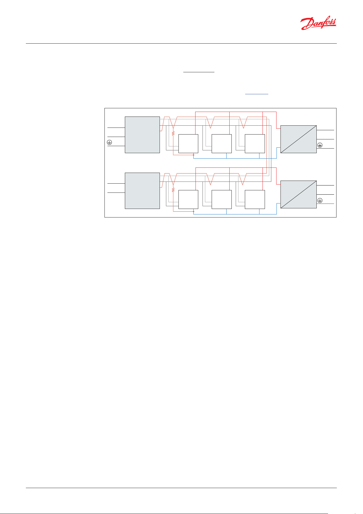
DGS with Modbus network communication in combination with other devices powered by more
than one power supply
It is strongly recommended to use direct current power supply when:
• more than 5 DGS units are powered by the same power supply
• the bus cable length is longer than 50 m for those powered units
It is moreover recommended to use class 2 power supply (see AK-PS 075)
Make sure to not interrupt the shield when connecting A and B to the DGS (see Fig. 4).
1 KΩ
1 KΩ
Shield
DGS 1
#adr n1
A
B Gnd
Shield
DGS 1
#adr n11
A
B Gnd
AK-PS 075 power supply
+
+
+
DGS 2
#adr n2
A
B Gnd
DGS 2
#adr n12
A
B Gnd
+
+
DGS n
#adr nx
A
B Gnd
DGS n
#adr ny
A
B Gnd
+
–
AK-PS 075 power supply
+
+
–
L
230 V
N
L
230 V
N
L
230 V
N
Danfoss
Modbus
device
AK-SM
A
B
Shld
Busslave
L
230 V
N
Danfoss
Modbus
device
AK-CC
A
B
Shld
Fig. 6: Wiring diagram for system with multiple power supplies
Ground potential difference between nodes of the RS485 network might affect the communication.
It is advised to connect a 1 KΩ 5% ¼ W resistor between the shield and the ground (X4.2) of any unit
or group of units connected to the same power supply (Fig. 6).
Please refer to Literature No. AP363940176099.
Power supply and voltage alarm
The DGS device goes into voltage alarm when voltage exceeds certain limits.
The lower limit is 16 V.
The upper limit is 28 V, if DGS software version is lower than 1.2 or 33.3 V in all other cases.
When in the DGS the voltage alarm is active, in the System Manager the “Alarm inhibited” is raised.
Danfoss
80Z878
8 | BC291049702513en-000201 © Danfoss | Climate Solutions | 2022.01

Gas Det ection Service Tool
Esc
←─
1
C
User Guide | Danfoss Gas sensor, type DGS
4. Operation The configuration and service is made via the hand-held Service Tool or in combination with the
MODBUS interface.
Security is provided via password protection against unauthorized intervention.
Hand-held Service Tool:
Operation is done via 6 buttons.
AK- System Manager:
The configuration is done via the graphical
display and buttons or via the PC tools
StoreView Desktop or AK-ST 500.
D1 R744 ppm
Warm-up Time
DGS Service Tool
Operation with the hand-held Service Tool is described in sections 4.1 – 4.3 and chapter 5. Operation
with the Danfoss Front End is described in chapter 6.
Two functions are configured via jumpers on the DGS.
Jumper 4, JP 4, located at the bottom left, is used to configure the MODBUS baud rate. As default the
baud rate is 38400 Baud. By removing the jumper, the baud rate is changed to 19200 Baud. Removing
the jumper is required for integrating with Danfoss System Managers AK-SM 720 and AK-SM 350.
Jumper 5, JP5, located at the top left, is used to configure the analogue output type.
As default this is voltage output. By removing the jumper, this is changed to current output.
Note: the DGS must be power cycled before any change to JP4 takes effect. JP1, JP2 and JP3 are not used.
x6
x5
Ackn.-/Test
button
1
2
3
1
2
3
Rel. 3
(critical)
Rel. 1
(warning)
4
3
x4
2
1
Danfoss
80Z790.1
BMODBUS
A+
24 V AC/D
+
open: 0-20mA
closed: 0-10V
x8
JP5
5
GND
4
AO_01
not used
2
DI_01
1
S&H supply
x1
LED
Yellow/Green/Red
x2
B&L
JP4
open: 19200 Baud
closed: 38400 Baud
Sensor 2
Tool
x9
Sensor 1
x3
JP3
JP2
JP1
not used
© Danfoss | Climate Solutions | 2022.01 BC291049702513en-000201 | 9

User Guide | Danfoss Gas sensor, type DGS
4.1 Function of the keys and
LEDs on the keypad
4.2 Setting / changing of
parameters and set points
ESC
The status LEDs indicate the operating status:
• Green
• Yellow
• Red
Continuous = alarm
The backlight of the display changes from green to red when an alarm is active.
Exits programming, returns to the previous menu level.
Enters sub menus, and saves parameter settings.
Scrolls up & down within a menu, changes a value.
Change of cursor position.
Continuous = operating voltage
Continuous = failure
Slowly flashing = warming-up
Fast flashing = special mode
Open desired menu window.
Code input field opens automatically if no code is approved.
After input of valid code, the cursor jumps to the first position segment to be changed.
Push the cursor to the position segment, which has to be changed.
Set the desired parameter / set point with the keys.
Save the changed value, confirm storage (ENTER).
ESC
4.3 Code levels All inputs and changes are protected by a four-digit numeric code (= password) against unauthorised
intervention according to the regulations of all national and international standards for gas warning
systems. The menu windows of status messages and measuring values are visible without entering a
code.
The access to the protected features is valid as long as the service tool remains connected.
The service technician’s access code to the protected features is ‘1234’.
Cancel the save / close editing / return to a higher menu level (ESCAPE function).
10 | BC291049702513en-000201 © Danfoss | Climate Solutions | 2022.01

User Guide | Danfoss Gas sensor, type DGS
5. Menu overview
Menu operation is done via a clear, intuitive and logical menu structure. The operating menu contains
the following levels:
• Starting menu with indication of the device type if no sensor head is registered, otherwise scrolling
display of the gas concentrations of all registered sensors in 5-second intervals.
• Main menu
• 5 sub menus under “Installation and Calibration”
Power On Time
19 sec.
Seconds indicator = 0
Danfoss
DGS
After about 2 seconds
1 R744 ppm
Warm-up Time
Power On Time of the basic device
Count down in seconds until the communication between the hand-held
Service Tool and the DGS is established. In case of communication error the
countdown will stop.
“Warm-up Time” is displayed. As soon as the sensor warm-up time has
expired, the measured value is displayed = measuring mode.
When the warm-up time has expired, the display will show the
measurement value - see section 4.4.
Note: with 2 sensor variants the screen will alternate between the two
sensors every 5 seconds.
Start menu
Main menu
Error Status
Alarm Status
Relay
Status
Measuring Values
Display
Parameters
Reading and acknowledgement of errors.
See chapter 5.1
Display of the status of active alarms.
See chapter 5.2
Display of the relay status. Protected by password.
See chapter 5.3
Display of measuring values.
See chapter 5.4
Read-out of hand-held tool version, language and set-up of
language. Partly protected by password.
See chapter 5.5
Installation &
Calibration
© Danfoss | Climate Solutions | 2022.01 BC291049702513en-000201 | 11
Reading and change of the relay, sensor head and
system parameters as well as test and calibration functions.

User Guide | Danfoss Gas sensor, type DGS
Menu overview
(continued)
Start menu
Main menu
Service
OFF
The following menu items are only accessible with Service ON (password protected)
!! Service ON = special mode = fault message is active!!
Alarm reset settings
Alarm settings
AO Settings
See chapter 5.6
See chapter 5.7
See chapter 5.8
Operating Data
Calibration
Addressing
5.1 Error status A pending fault activates the yellow LED (Fault). The first 50 pending errors are displayed in the menu
“System Errors“.
A number of error messages may be displayed related to the sensor: Out of Range, Wrong type,
Removed, Calibration due, Voltage Error. “Voltage Error” refers to the supply voltage. In this case the
product will not go into normal operation until the supply voltage is within the specified range.
See chapter 5.9
See chapter 5.10
See chapter 5.11
12 | BC291049702513en-000201 © Danfoss | Climate Solutions | 2022.01

User Guide | Danfoss Gas sensor, type DGS
5.2 Alarm Status Display of the currently pending alarms in plain text in the order of their arrival. Only those sensor
heads are displayed, where at least one alarm is active.
Alarms in latching mode (latching mode is only valid for certain DGS types, DGS-PE) can be
acknowledged in this menu (only possible if the alarm is not active).
Alarm Status
Symbol Description Function
DP 1 Sensor head No.
‘A1
‘‘A1
Alarm status
DP 1
“A1
5.3 Relay Status Reading of the current status of alarm relays.
The actual relay status is displayed, depending on the relay mode (energized <> de-energized).
Selection of alarm relay:
Alarm Relay
Status
Alarm Relay 1
Status OFF
Selection of the next alarm relay
Symbol Description Function
1 Alarm Relay
OFF Relay Status Relay OFF = coil de-energized
ON Relay Status Relay ON = coil energized
Note: Relay 3 is used for critical alarm indication. Relay 1 may be configured for critical alarm indication with the
2-sensor variant. A critical alarm relay has a Normally Closed contact set which indicates an alarm if the power to
the DGS is lost. In the table above the relays status refers to energizing of the coil, which activates the contact set.
Hence, for a critical relay in normal operation the coil is energized, causing the contact set to open and the relay
status to read “ON”. In the alarm condition, the coil is de-energized, causing the contact set to close and the relay
status to read “OFF”.
Gasfree state
ascertained?
DP 1: Sensor 1
DP 2: Sensor 2 (2-sensor variant only)
‘ = Alarm active
‘’ = Alarm in latching mode, can be acknowledged
1 = Relays 1 = Warning relay
3 = Relay 3 = Critical relay
1 = Relays 1 = Warning relay
2 = Buzzer
3 = Relay 3 = Critical relay
5.4 Menu Measuring Values
In this menu, the display shows the measuring value with gas type and unit.
Measuring Values 1 R744 ppm
A ! 450
Selection of the next sensor head
Symbol Description Function
1 Actual MODBUS address 1: MODBUS address = 1
R744 Gas type Display of gas type (must comply with gas type of sensor head)
ppm Gas unit Unit
51.0 °C Measured value Current value of the gas concentration
A! Alarm indication At least one alarm has been released at this sensor head
# Maint. info Sensor head: maintenance due (maintenance date exceeded)
? ConfigError Gas type or meas. range does not comply with sensor head
Comm. err. Fault sensor head Communication error, sensor head <> I/O board
Underrange
Overrange
Warm-up Warm-up time Warm-up time of the sensor is active
Meas. range monitoring
Meas. signal < admissible range (< zero point – 6 %)
Meas. signal > admissible range (> full scale value + 6 %)
AO Value
10.0 V 20.00 mA
The actual analogue output value in voltage and milliampere.
© Danfoss | Climate Solutions | 2022.01 BC291049702513en-000201 | 13

User Guide | Danfoss Gas sensor, type DGS
5.5 Display Parameters In the menu display parameters you can find the general parameters of the Service Tool and the DGS.
Display
Parameters
5.5.1 Software Version
Software Version
XXXXX - YYYYY
Software version of the hand-held Service Tool and of the DGS.
Symbol Description Function
XXXXX Software Version of the Service Tool XXXXX Software Version
YYYYY Software Version of the DGS YYYYY Soft ware Version
5.5.2 Language
Language
English
Selection of the menu language (password protected)
Symbol Description Default Function
English
English Language English
Spanish
French
Italian
German
5.5.3 LCD Function Check Function for testing the LCD function (password protected) All LEDs light up for about two seconds.
The backlight is yellow. All points are displayed on the LCD.
LCD Function
check?
5.6 Alarm Reset Settings This section describes how the DGS reacts when an active alarm is reset (acknowledged).
Alarm Reset
Settings
5.6.1 Relay Reset This defines if the relay resets to “no alarm condition” state when a critical alarm is reset (acknowledged).
Symbol Description Default Function
Relay Rst
Enable
Function ON ON = Relays reset when an active alarm is reset
(acknowledged).
OFF = The alarm relay remains active even if the
alarm is acknowledged (it is useful to keep ventilation
system running until concentration is below the alarm
threshold).
Relay Rst Enable
ON
14 | BC291049702513en-000201 © Danfoss | Climate Solutions | 2022.01

User Guide | Danfoss Gas sensor, type DGS
5.6.2 Alarm reset duration This defines how long the alarm reset is active (alarm acknowledged).
Time
300
Symbol Description Default Function
Reset Alarm
Time
Relay Rst Enable
Function
300 Defines how many seconds the alarm reset condition
is active. If the alarm condition has not cleared within
this time, the alarm will be re-activated without any
further delay (Buzzer, and if configured, also the relay)
0: The alarm reset function is disabled.
5.7 Alarm Settings
5.7.1 Room mode
5.7.2 Alarm limits
Reading and changing (only via code level 1) of Alarm Settings.
MP 1
active
Warning limit
C 5000 ppm
This function is only available for measuring point 2 (MP2). It defines if the sensors share the critical
relay and the warning relay (both sensors mounted in same room) or each sensor has 1 critical relay
each (two rooms with one sensor).
In the menu structure, this setting is accessible under sensor 2 only (MP2).
Room Mode
1 Room
Symbol Description Default Function
Room Mode Function 1 Room 1 Room: Relay 1 is used as warning relay for both
For each sensor head two alarm thresholds
are available for free definition. If the gas
concentration is higher than the set alarm
sensors and relay 3 is used as critical relay for both
sensors.
2 Rooms: Relay 1 is used as a critical relay for sensor 1
and relay 3 is used as critical relay for sensor 2.
Warning limit
C 5000 ppm
threshold, the associated alarm is activated. If the
gas concentration falls below the alarm threshold
inclusive hysteresis, the alarm is reset again.
The hysteresis of both alarm is 5% of the default
alarm threshold (e.g. with 5000 ppm this
Critical limit
C 5000 ppm
corresponds to 250 ppm).
Note: With propane (R290), the alarm status
will not auto-clear if the measured ppm-value
has exceeded the max-range of the sensor
element. In this case the concentration may be as
indicated OR it may still be above the max-range.
The alarm must be manually cleared and the
room checked before entry.
Delay Alarm ON
0 sec.
5.7.3 Alarm relay
For setting the alarm delay for Critical and
Warning alarms.
Symbol Description Default Function
0 sec. Delay Alarm 0 sec.
Gas concetration > alarm threshold + set time = Alarm ON
Gas concentration < alarm threshold – hysteresis = Alarm OFF
© Danfoss | Climate Solutions | 2022.01 BC291049702513en-000201 | 15

User Guide | Danfoss Gas sensor, type DGS
5.8 AO Settings
AO Settings
Analog Output 1
50% -- min = 0 V.
This menu is for the configuration of the
analogue outputs.
If more than one sensor head is present, the
maximum value of the two measurements is
assigned to the output.
Using this function, it is possible to configure the
output signal.
The CO sensor with a range of 0 – 20000 ppm
has an output signal of 0 – 10 V corresponding to
0 – 10000 ppm as default.
As an example this may be changed to
e.g. 2 – 10 V for 0 – 20000 ppm by changing
settings to “100%” and “2 V ”.
Symbol Description Default Function
50%
100%
- -
0 V
2 V
Selection of the ppm
measurement which will
give the maximum output
signal
DANFOSS ONLY SETTING
Selection of minimum
output signal
50%
--
0 V
50% = at a concentration of 50% of the sensor head range the
output will be set to 10 V (20 mA without JP5 mounted)
100% = at a concentration of 100% of the sensor head range the
output will be set to 10 V (20 mA without JP5 mounted)
Do not change – If doing so, a small “noise signal” (step form) on
top of the measured ppm value with a duty cycle of app. 180s is
activated.
0 V = at the minimum measuring signal of the sensor, the output will
be set to 0V (0 mA without JP5 mounted)
2 V = at the minimum measuring signal of the sensor, the output will
be set to 2 V (4 mA without JP5 mounted)
The analogue output signal depends on above settings and the configuration of jumper JP5. The
output signal is continously monitored by the DGS. If the value deviates by more than 5% from the
expected value, an Error Message is generated. This might happen if the output is short-circuited. If
configured for current output (JP5 open) the alarm is also generated if the output is open-circuited.
In below examples, it is assumed that the output is in voltage (JP5 closed) and that a 0 – 20000 ppm
sensor is used.
The analogue output signal, AO is calculated by this formula:
ppm value
AO =
ppm range
x AO range + AO min.
Example 1 (default settings):
“AO output max. scaling” = 50%
“AO min. value” = 0 (default)
This means that in the formula:
• AO range = 10 V
• AO min. = 0 V
• ppm range = 10000 ppm
Hence, a measured value of 4000 ppm will result in the following output value:
4000 ppm
AO = x 10 V + 0 V = 4 V
10000 ppm
Example 2:
“AO output max. scaling” = 100%
“AO min. value” = 2 V
This means that in the formula:
• AO range = 8 V
• AO min. = 2 V
• ppm range = 20000 ppm
Hence, a measured value of 4000 ppm will result in the following output value:
4000 ppm
AO =
20000 ppm
x 8 V + 2 V = 3.6 V
16 | BC291049702513en-000201 © Danfoss | Climate Solutions | 2022.01

User Guide | Danfoss Gas sensor, type DGS
5.9 Operating Data
This menu is for retrieving relevant operational data from the sensor head.
No changes or modifications are possible.
Operating Data
Operating Data
SC
If more than one sensor head is connected to
the DGS, the selection is done at X.
Operating Data
SC X
Software version
XXXX
Days of Operation
X Days
Software version of the sensor head.
Current days of operation.
Days of Operation
expected XXX
Min. Temperature
25 °C
Max. Temperature
25 °C
Number of Calib.
X
Sensitivity
XXX%
Days of Operation
Last XXX
Expected remaining lifetime (in days) of
the sensor head.
Display of the lowest temperature
detected by the device.
Display of the highest temperature
detected by the device.
How many times the sensor head has
been calibrated.
Remaining sensitivity of the sensor.
Must be replaced when below 35%. The
value is only updated immediately after
calibration.
Days of operation since the last
calibration took place.
Maintenance Days
remaining XXXX
© Danfoss | Climate Solutions | 2022.01 BC291049702513en-000201 | 17
Days until the next calibration is due.

User Guide | Danfoss Gas sensor, type DGS
5.10 Calibration
This section gives an overview of the calibration menu.
The calibration description can be found on the following pages.
For HFC, remember to use the specified calibration gas.
(HFC grp 1 = R1234yf, grp 2 = R134a, grp 3 = R407c)
Calibrate
DP 1
Sxxx R744 ppm
Selection of the
sensor head to
be calibrated
Zero DP 1
Calibration gas
XXXX ppm
Gain DP 1
Zero calibration.
See section 4.10.1
Set the test gas concentration.
Gain calibration.
See section 4.10.2
Calibration AO 1
Burn clean
See section 4.10.3
Only available for combustible gases
(propane).
18 | BC291049702513en-000201 © Danfoss | Climate Solutions | 2022.01

User Guide | Danfoss Gas sensor, type DGS
5.10.1 Zero calibration
The stepwise calibration process is described below.
Note: The specified warm-up times etc. must be strictly observed before starting the calibration
process.
Zero DP 1
Zero DP 1
100 ppm
Zero DP 1
90 ppm
Step 1: Display of the current value.
Step 2: Apply test gas according to instructions.
Step 3: Start calibration process.
Step 4: Calculation of the new zero point.
During calculation an underscore in line two runs from left to
right and the current value drops to zero.
Step 5: When the current value is stable, press for
finishing the calculation of the new value.
Zero DP 1
SAVE
Zero DP 1
0 ppm
Step 6: Save the newly calculated zero point.
“SAVE“ is displayed, as long as the function is executed.
After the value has been successfully stored, a square appears
on the right for a short time = zero point calibration is finished
and new zero offset has been stored with success.
Zero DP 1
0 ppm
The display automatically goes to step 1: Display of new zero
point.
During the calculation phase, the following messages may occur:
Message Description
Current value too high Wrong gas for zero point calibration or sensor element defective. Replace sensor head.
Current value too small Wrong gas for zero point calibration or sensor element defective. Replace sensor head
Current value unstable
Time too short
Internal error
Appears when the sensor signal does not reach the zero point within the target time. Disappears
automatically when the sensor signal is stable.
The message “value unstable” starts an internal timer. Once the timer has run out and the current
value is still unstable, the text is displayed. The process starts over again. If the value is stable,
the current value is displayed and the calibration procedure is continued. If the cycle is repeated
several times, an internal error has occurred. Stop the calibration process and replace the sensor
head.
Calibration is not possible → check if burning clean process is completed or interrupt it manually
or check/replace sensor head.
If aborting the zero offset calibration, the offset value will not be updated. The sensor head continues
to use the “old” zero offset. A full calibration routine must be conducted to save any calibration
change.
© Danfoss | Climate Solutions | 2022.01 BC291049702513en-000201 | 19

User Guide | Danfoss Gas sensor, type DGS
5.10.2 Gain calibration
The stepwise calibration process is described below.
Note: The specified warm-up times etc. must be strictly observed before starting the calibration
process.
Test Gas
XX.X ppm
Enter concentration of the test gas used.
This value is not cleared when exiting the menu, therefore always check if
the value is correct before calibrating.
Gain DP 1
Gain DP 1
100 ppm 100%
Step 1: Display of the current value and of the sensitivity
from the last calibration.
Step 2: Apply test gas according to instructions.
Step 3: Start calibration process.
Gain DP 1
_90 ppm
Step 4: Calculation of the new gain.
During calculation an underscore in line two runs from left
to right and the current value converges to the set test gas
concentration. The sesitivity is recalculated, too.
Step 5: When the current value is stable, press for
finishing the calculation of the new value.
Gain DP 1
SAVE
Step 6: Save the newly calculated gain.
‘SAVE‘ is displayed as long as the function is executed.
Gain DP 1
0.0 ppm
Gain DP 1
After the value has been successfully stored, a square appears
on the right for a short time = Gain calibration is finished and
new gain offset has been stored with success.
The display automatically goes to step 1: Display
0.0 ppm
During the calculation phase, the following messages may occur:
Message Description
Current value too high
Current value too low No test gas or wrong test gas applied to the sensor.
Test gas too high
Test gas too low
Current value unstable
Time too short
Sensitivity < Sensitivity of the sensor head < 30%, calibration no longer possible → replace sensor head.
Internal error
Test gas concentration > than set value
Internal error → replace sensor head
The set test gas concentration must be between 30% and 90% of the measuring range.
Appears when the sensor signal does not reach the calibration point within the target time.
Disappears automatically when the sensor signal is stable.
The message “value unstable” starts an internal timer. Once the timer has run out and the current
value is still unstable, the text is displayed. The process starts over again. If the value is stable,
the current value is displayed and the calibration procedure is continued. If the cycle is repeated
several times, an internal error has occurred. Stop the calibration process and replace the sensor
head.
Calibration is not possible → check if burning clean process is completed or interrupt it manually
or check/replace sensor head.
20 | BC291049702513en-000201 © Danfoss | Climate Solutions | 2022.01

User Guide | Danfoss Gas sensor, type DGS
5.10.3 Zero point calibration of
analogue output
With this menu item you can adjust the zero point of the analogue output (4mA). The zero point
correction is only possible when the minimum output is 2 V or 4 mA, i.e. not possible when minimum
output is 0 V or 0 mA.
The error message of the output monitoring is suppressed as long as the menu Calibration AO is open.
Therefore, connect the ampere meter (measuring range 20 mA DC) to the analogue output only after
having opened the menu.
Calibration AO 1
Connect ampere meter to the analogue output.
Calibration AO 1
Display of the current zero offset on the left.
320 0
Calibration AO 1
320 323
Calibration AO 1
Adjust the zero offset on the right by changing the offset value
slowly, until the ampere meter shows the desired value.
Save the adjusted zero offset.
SAVE
Calibration AO 1
Return to the display of the current zero offset.
323 323
5.11 Addressing
Addressing
Assignment of the MODBUS address of the device for system integration, e.g. with
Danfoss front end type AK-SM 800.
Set Address
Define the MODBUS address.
4
Symbol Description Default Function
4 MODBUS Address 0 0 = Device is not addressed, BUS not used. Max. value is 240.
© Danfoss | Climate Solutions | 2022.01 BC291049702513en-000201 | 21

User Guide | Danfoss Gas sensor, type DGS
6. MODBUS menu survey
Function Min. Max. Factory Unit AKM name
Gas level
Sensor 1 Actual gas level in % of range 0.0 100.0 - % Gas level %
Sensor 1 Actual gas level in ppm 0 FS1 - ppm Gas level ppm
Sensor 2 Actual gas level in % of range 0.0 100.0 - % 2: Gas level %
Sensor 2 Actual gas level in ppm 0 FS1 - ppm 2: Gas level ppm
Alarms Alarm settings
Indication of critical alarm (critical alarm of Gas 1 or Gas 2 active)
0: No active alarm(s)
1: Alarm(s) active
Common indication of both critical and warning alarm as well as internal and
maintenance alarms
0: No active alarm(s), warning(s) or errors
1: Alarm(s) or warning(s)) active
Gas 1 Critical limit in %.
Critical limit in % (0-100)
Gas 1 Critical limit in ppm
Critical limit in ppm; 0: Warning Signal deactivated
Gas 1 Warning limit in % (0-100) 0 100.0 HFC: 25
Gas 1
Warning limit ppm 0: Warning Signal deactivated
High (critical and warning) alarm delay in seconds, if set to 0: no delay 0 600 0 sec. Alarm delay s
When set to 1, the Buzzer is reset (and the relays if defined: Relay rest enable)
to no alarm indication. When the alarm is reset or
the time-out duration is exceeded, the value is reset to 0.
Note: The alarm condition is not reset - only the output indication is reset.
0: Alarm outputs not reset
1: Alarm outputs reset–Buzzer muted and relays reset if configured
Duration of alarm reset before automatic re-enable of alarm outputs. A setting of 0 disables the ability to reset alarm.
Relay reset enables:
Relay reset with alarm acknowledge function
1: (default) Relays wil be reset if the alarm acknowledge function is activated
0: Relays remain active until the alarm condition clears
Gas 2 Critical limit in %.
Critical limit in % (0-100)
Gas 2 Critical limit in ppm
Critical limit in ppm; 0: Warning Signal deactivated
Gas 2. Warning limit in % (0-100) 0 100.0 CO: 25 % 2: Warn. limit %
Gas 2. Warning limit ppm 0: Warning Signal deactivated 0.0 FS1 CO: 5000 ppm 2: Warn. limit ppm
High (critical and warning) alarm delay in seconds, if set to 0: no delay 0 600 0 sec. 2: Alarm delay s
Configuration of relays for one or two rooms’ application mode.
1: One room with two sensors sharing the same warning relay and critical relay
2: Two rooms with one sensor in each, and each sensor having a critical alarm
relay. In this mode, warning alarms activate as normal on the LED indicator,
hand-held Service Tool and on MODBUS.
Service
Status of the sensors’ warm-up period
0: Ready
1: Warming up one or more sensors
0 1 - - GD alarm
0 1 - - Common errors
0.0 100.0 HFC: 25
CO: 25
R290: 16
0 FS1 HFC: 500
CO: 5000
R290: 800
CO: 25
R290: 16
0.0 FS1 HFC: 500
CO: 5000
R290: 800
0 1 0 - Reset alarm
0 9999 300 sec. Reset alarm time
0 1 1 - Relay rst enable
0.0 100.0 CO: 25 % 2: Crit. limit %
0 FS1 CO: 5000 ppm 2: Crit. limit ppm
1 2 1 - 2: Room Mode
0 1 - - DGS Warm-up
% Crit. limit %
ppm Crit. limit ppm
% Warn. limit %
ppm Warn. limit ppm
) The max. alarm limit for CO is 16.000 ppm / 80% of full scale. All other values equal the full scale range of the specific product.
22 | BC291049702513en-000201 © Danfoss | Climate Solutions | 2022.01

User Guide | Danfoss Gas sensor, type DGS
Readout the attached gas sensor type.
1: HFC grp 1
R1234ze, R454C, R1234yf
R1234yf, R454A, R455A, R452A
R454B, R513A
2: HFC grp 2
R407F, R416A, R417A
R407A, R422A, R427A
R449A, R437A, R134A
R438A, R422D
3: HFC grp 3
R448A, R125
R404A, R32
R507A, R434A
R410A, R452B
R407C, R143B
4: CO
5: Propane (R290)
Full scale range 0 32000 HFC: 2000
Gas 1 Days until next calibration 0 32000 HFC: 365
Gas 1 Estimates how many days remaining for sensor 1 0 32000 - days Rem.life time
Status of the critical alarm relay:
1: ON = no alarm signal, coil under power - normal
0: OFF = alarm signal, coil depowered, alarm situation
Status of the warning relay:
0: OFF = inactive, no warning active
1: ON = active warning, coil under power
Status of the Buzzer:
0: inactive
1: active
Gas 2 Days until next calibration 0 32000 HFC: 365
Gas 2 Estimates how many days remaining for sensor 2 0 32000 - days 2: Rem.life time
Activates a mode which simulates an alarm. Buzzer, LED and relays all
activate.
1:-> Test function - no alarm generation possible now
Automatically falls back to Off after 15 min.
0: back to normal mode
Analogue output max. scaling
0: zero to full scale (e.g (Sensor 0 – 2000 ppm) 0 – 2000 ppm will give 0 – 10 V)
1: zero to half scale (e.g (Sensor 0 – 2000 ppm) 0 – 1000 ppm will give 0 – 10 V)
Analogue output min. value
0: select 0 – 10 V or 0 – 20 mA output signal
1: select 2 – 10 V or 4 – 20 mA output signal
Alarms
Critical Limit alarm
0: OK
1: Alarm. Gas limit exceeded and delay expired
0: OK
1: Fault. Out of range under test – over range or under range
0: OK
1: Fault. Sensor and head failures
0: OK
1: Fault. Sensor out or removed, or wrong sensor connected
0: OK
1: Warning. Due for calibration
0: OK
1: Warning. Gas level above warning level and delay expired
Indication if the normal alarm function is inhibited or in normal operation:
0: Normal operation, i.e. alarms are created and cleared
1: Alarms inhibited, i.e. alarm status is not updated, e.g. due to DGS in test
mode
1 5 N - Sensor type
CO: 20000
R290: 5000
CO: 1825
R290: 182
0 1 - - Critical Relay
0 1 - - Warning Relay
0 1 - - Buzzer
CO: 1825
R290: 182
0 1 0 - Test Mode
0 1 HFC: 1
CO: 1
R290: 0
0 1 0 - AOmin = 2V/4mA
0 1 - - Critical limit
0 1 - - Out of range
0 1 - - Wrong SensorType
0 1 - - Sensor removed
0 1 - - Calibrate sensor
0 1 - - Warning limit
0 1 - - Alarm inhibited
ppm Full scale ppm
days Days till calib
days 2: Days til calib.
- AOmax = half FS
© Danfoss | Climate Solutions | 2022.01 BC291049702513en-000201 | 23

Critical Limit alarm
0 1 - - 2: Criti. limit
0: OK
1: Alarm. Gas limit exceeded and delay expired
0: OK
0 1 - - 2: Out of range
1: Fault. Out of range under test – over range or under range
0: OK
0 1 - - 2: Wrong SensType
1: Fault. Sensor and head failures
0: OK
0 1 - - 2: Sens. removed
1: Fault. Sensor out or removed, or wrong sensor connected
0: OK. Sensor not due for calibration
0 1 - - 2: Calibrate sens.
1: Warning. Due for calibration
0: OK
0 1 - - 2: Warning limit
1: Warning. Gas level above warning level and delay expired
7. Ordering
DGS Sensors Spares and accessories
Product Description Code no. Product Description Code no.
DGS-SC H FC grp 1* 080Z2803 Spare sensor HFC grp 1* Spare 080Z2815
DGS-SC H FC grp 2* 080Z2804 Spare sensor HFC grp 2* Spare 080Z2816
DGS-SC H FC grp 3* 080Z2805 Spare sensor HFC grp 3* Spare 080Z2817
DGS-PE propane 080Z2806 Spare sensor propane Spare 080Z2818
DGS- IR CO 080Z2800 Spare sensor CO Spare 080Z2813
DGS- IR CO 5 m 080Z2801 Spare sensor CO - 5 m Spare 080Z2814
DGS-IR 2 * CO - 5 m 080Z2802 Hand-held Service Tool Accessory 080Z2820
DGS-SC H FC grp 1* + B&L 080Z2809 Strobe & Horn Accessory 080Z2819
DGS-SC H FC grp 2* + B&L 080Z2810 Splash guard Accessory 148H6226
DGS-SC H FC grp 3* + B&L 080Z2811 Duct se t Accessory 148 H6236
DGS-PE propane + B&L 080Z2812 Calibration adaptor Accessory 148 H6232
DGS- IR CO + B&L 080Z2807 Remote kit Accessory 148H6238
DGS- IR CO 5 m + B&L 080Z2808 Power Supply AK-PS075 Accessory 080Z0053
* HFC grp 1: R1234ze, R454C, R1234y f, R454A, R455A, R452A, R454B, R513A
HFC grp 2: R407F, R416A, R417A, R407A, R422A, R427A, R449A, R437A, R134 A, R438A, R422D
HFC grp 3: R448A, R125, R404A, R32, R507A, R434A, R410A, R452B, R407C , R143B
Bold = calibration gas
Note: DGS is also available for alternative refrigerant gases on request. Please contact your local Danfoss sales office for details.
© Danfoss | Climate Solutions | 2022.01 BC291049702513en-000201 | 24
 Loading...