

Page 1

Installation Guide
Danfoss Gas Sensor
080R9333
Type DGS
ENGLISH
Technician use only!
This unit must be installed by a suitably qualified technician who
will install this unit in accordance with these instructions and the
standards set down in their particular industry/country.
Suitably qualified operators of the unit should be aware of the
regulations and standards set down by their industry/country for
the operation of this unit.
These notes are only intended as a guide, and the manufacturer
bears no responsibility for the installation or operation of this unit.
Failure to install and operate the unit in accordance with these
instructions and with industry guidelines may cause serious
injury including death, and the manufacturer will not be held
responsible in this regard.
It is the installer’s responsibility to adequately ensure that the
equipment is installed correctly and set up according to the
environment and the application in which the products are being
used.
Please observe that DGS works as a safety device securing a
reaction to a detected high gas concentration. If a leakage
occurs, the DGS will provide alarm functions, but it will not
solve or take care of the leakage root cause itself.
AN284527372096en-000301
Regular Test:
To maintain product performance and comply with the local
requirements, the DGS must be tested regularly.
DGSs are provided with a test button that may be activated to
validate the alarm reactions.
Additionally, the sensors must be tested by either bump test or
calibration.
Danfoss recommends the following minimum calibration intervals:
DGS-IR: 60 months
DGS-SC: 12 months
DGS-PE: 6 months
With DGS-IR it is recommended to do an annual bump test in years
without calibration.
Check local regulations on calibration or testing requirements.
Do not spray or pour pure refrigerant or other liquids onto the
sensor head to perform a bump test. This may significantly reduce
the lifetime of the sensor head or even destroy it.
For propane: after exposure to a substantial gas leak, the sensor
should be checked by bump test or calibration and replaced if
necessary.
Location:
For all gases heavier than air, Danfoss recommends placing the
sensor head app. 30cm (12") above the floor and, if possible, in the
air flow. All gases measured with these DGS sensors are heavier
than air: HFC grp 1, HFC grp 2, HFC grp 3, CO and Propane.
Dimensions and appearance
For further details on Test and Location please see the Danfoss
Application Guide: "Gas detection in refrigeration systems".
Fig. 1
© Danfoss | Climate Solutions | 2022.01
AN284527372096en-000301 | 1
Page 2

Cable gland opening
Danfoss
1
C
148H126_01-2018
Hole punching for cable gland:
1. Select the location for the safest cable entry
2. Use a sharp screwdriver and a small hammer
3. Place the screwdriver and hammer with precision
while moving the screwdriver within a small area
until the plastic is penetrated.
Fig. 2
Danfoss Gas Sensor DGS
5
GND
4
AO_01
not used
2
DI_01
1
S&H supply
x1
LED
Yellow/Green/Red
Sensor 2
x9
open: 0-20mA
closed: 0-10V
B&L
open: 19200 Baud
closed: 38400 Baud
JP5
x8
x2
JP4
Continue precision punching with small movements
until the round piece can be pulled out with your
fingers.
WARNING: be very careful not to damage
the internal board components with the
screwdriver.
Status LED / B&L:
GREEN is power on.
- flashing if maintenance needed
YELLOW is an indicator of Error.
- the sensor head is disconnected or not the expected type
- AO configured as 0 – 20 mA, but no current is
80Z790.1
running
- flashing when sensor is in special mode (e.g. when
- Supply voltage out of range
RED flashing: is an indication of alarm due to gas
concentration level. The Buzzer & Light behaves identical
to the status LED.
x6
x5
Ackn.-/Test
button
1
2
3
1
2
3
Rel. 3
(critical)
Rel. 1
(warning)
4
3
x4
2
1
Danfoss
BMODBUS
A+
24 V AC/D
+
Ackn. / Test button / DI_01:
TEST: The button must be pressed for 8 sec.
Tool
JP3
x3
JP2
JP1
not used
- Critical and warning alarm is simulated and AO goes to
ACKN: If pressed during critical alarm, as default* the relays
and Buzzer go out of alarm condition and back on after 5
minutes if the alarm situation is still active.
* the duration and whether to include the relay status with this
function or not is user defined.
Sensor 1
DI_01 (terminals 1 and 2) is a dry-contact (potential-free)
behaving identically to the Ackn./Test button.
Remove potential burrs and secure flat surfaces.
Install the cable gland according to the enclosed guide.
changing parameters with the Service Tool)
max. (10 V/20 mA), stops on release.
Note: For what concern the power supply, please refer to chapter 3.10 Power Con-
ditions and Shielding Conceptions in the User Guide (BC291049702513en-000201).
A Class II power supply is recommended
Fig. 3
2 | AN284527372096en-000301
DC supply for external Strobe&Horn
Whether the DGS is powered by 24 V DC or 24 V AC, a 24
V DC power supply (max. 50 mA) is available between
terminals 1 and 5 on connector x1.
Jumpers
* JP4 open → 19200 Baud
JP4 closed → 38400 Baud (default)
* JP5 open → AO 0 – 20 mA
JP5 closed → AO 0 – 10 V (default)
Note: the DGS must be power cycled before any change to
JP4 takes effect.
Analog Output:
If the analog output AO_01 is used (terminals 4 and 5) then
you need the same ground potential for the AO and the
connected device.
Note: JP1, JP2 and JP3 are not used.
© Danfoss | Climate Solutions | 2022.01
Page 3

DGS installation instructions
The DGS is available with one or two sensors and B&L (Buzzer and
Light) as option (see fig. 1).
For sensors that can be poisoned by e.g. silicones like all
semiconductor and catalytic bead sensors, it is imperative to only
remove the protective cap after all silicones are dry, and then
energize the device.
The sensor protection cap must be removed before taking the
DGS into operation
Mounting and wiring
To wall mount the DGS, unscrew the lid by releasing the four
plastic screws in each corner and remove the lid. Mount the DGS
base to the wall by fitting screws through the holes which the lid
screws were fastened by. Complete the mounting by re-applying
the lid and fastening the screws.
The sensor head must always be mounted so that it points
downwards. The DGS-IR sensor head is sensitive to shock – special
attention should be paid to protect the sensor head from shocks
during installation and operation.
Observe the recommended placing of the sensor head as stated
on page 1.
Extra cable glands are added by following the instruction in fig. 2.
The exact position of the terminals for the sensors, alarm relays,
digital input and analogue output is shown in the connection
diagrams (see fig. 3).
The technical requirements and regulations for wiring,
electrical security, as well as project specific and environmental
requirements and regulations must be met.
Configuration
For convenient commissioning, the DGS is pre-configured and
parameterized with factory-set defaults. See Menu Survey on
page 5.
Jumpers are used to change the analogue output type and the
MODBUS baud rate. See fig. 3.
For DGS with Buzzer & Light, alarm actions are given according to
following table below.
System integration
To integrate the DGS with a Danfoss system manager or general
BMS system, set the MODBUS address using the DGS Service Tool,
using password "1234" when prompted. See the DGS User Guide
for details on operating the DGS Service Tool.
The Baud Rate is adjusted by jumper JP4. As default, the setting
is 38.4k Baud. For integration with AK-SM 720/350 change the
setting to 19.2k Baud.
For more information about data communication see Danfoss
document RC8AC--
Sensor replacement
The sensor is connected to the DGS via a plug connection
enabling simple sensor exchange instead of an on-site calibration.
The internal replacement routine recognizes the exchanging
process and the exchanged sensor and re-starts the measurement
mode automatically.
The internal replacement routine also examines the sensor for
actual type of gas and actual measuring range. If the data does not
match the existing configuration, the built-in status LED indicates
an error. If everything is OK the LED will light up green.
As an alternative, the on-site calibration via the DGS Service Tool
can be performed with the integrated, user friendly calibration
routine.
See the DGS User Guide for details on operating the DGS Service
Tool.
Action Reaction
Loss of power to DGS OFF OFF X (closed)
Gas signal < warning alarm threshold OFF GREEN
Gas signal > warning alarm threshold OFF RED Slow flashing X (closed)
Gas signal > critical alarm threshold ON RED Fast flashing X (closed) X (closed)
Gas signal ≥ critical alarm threshold,
but ackn. button pressed
No alarm, no fault OFF GREEN
No fault, but maintenance due OFF GREEN Slow flashing
Sensor communication error OFF YELLOW
DGS in special mode OFF YELLOW flashing
Alarm thresholds can have the same value, therefore both the relays and the Buzzer
and Light can be triggered simultaneously.
The alarm thresholds have a hysteresis of app. 5%
* whether to include the relay status with the acknowledge function or not is user
defined.
** If the DGS has two sensors and the "Room Mode" is configured to "2 rooms",
then relay 1 ac ts as a critical relay for sensor 1 and relay 3 acts as a critical
relay for sensor 2. Both relays are SPDT NC. The Buzzer and Light operation is
independent of the "Room Mode" setting.
Buzzer
OFF
(ON after delay)
Reaction
Light
RED Fast flashing X (closed)* (open)*
Warning relay 1**
SPDT NO (Normally Open)
Critical relay 3**
SPDT NC (Normally closed)
© Danfoss | Climate Solutions | 2022.01
AN284527372096en-000301 | 3
Page 4

DGS installation test
As DGS is a digital device with self-monitoring, all internal errors
are visible via the LED and MODBUS alarm messages.
All other error sources often have their origins in other parts of the
installation.
For fast and comfortable installation test we recommend
proceeding as follows.
Optical Check
Right cable type used.
Correct mounting height according to definition in the section
about mounting.
LED status – see DGS trouble shooting.
Functional test (for initial operation and maintenance)
Functional test is done by pressing the test button for more than
8 seconds and observing that all connected outputs (Buzzer, LED,
Relay connected devices) are working properly. After deactivation
all outputs must automatically return to their initial position.
Zero-point test (if prescribed by local regulations)
Zero-point test with fresh outdoor air.
A potential zero offset can be read out by use of the Service Tool.
Trip test with reference gas (if prescribed by local regulations)
The sensor is gassed with reference gas (for this you need a gas
bottle with pressure regulator and a calibration adapter).
In doing so, the set alarm thresholds are exceeded, and all output
functions are activated. It is necessary to check if the connected
output functions are working correctly (e.g. the horn sounds, the
fan switches on, devices shut down). By pressing the push-button
on the horn, the horn acknowledgement must be checked. After
removal of the reference gas, all outputs must automatically return
to their initial position.
Other than the trip testing, it is also possible to perform a
functional test by means of calibration. For further information,
please refer to the User Guide.
Comparing sensor gas type with DGS specification
The replacement sensor specification must match the DGS
specification.
The DGS software automatically reads the specification of the
connected sensor and compares with the DGS specification.
This feature increases the user and operating security.
New sensors are always delivered factory-calibrated by Danfoss.
This is documented by the calibration label indicating date
and calibration gas. A re-calibration is not necessary during
commissioning if the device is still in its original packaging
(including air-tight protection by the red protective cap) and if the
calibration certificate has not expired.
4 | AN284527372096en-000301
© Danfoss | Climate Solutions | 2022.01
Page 5
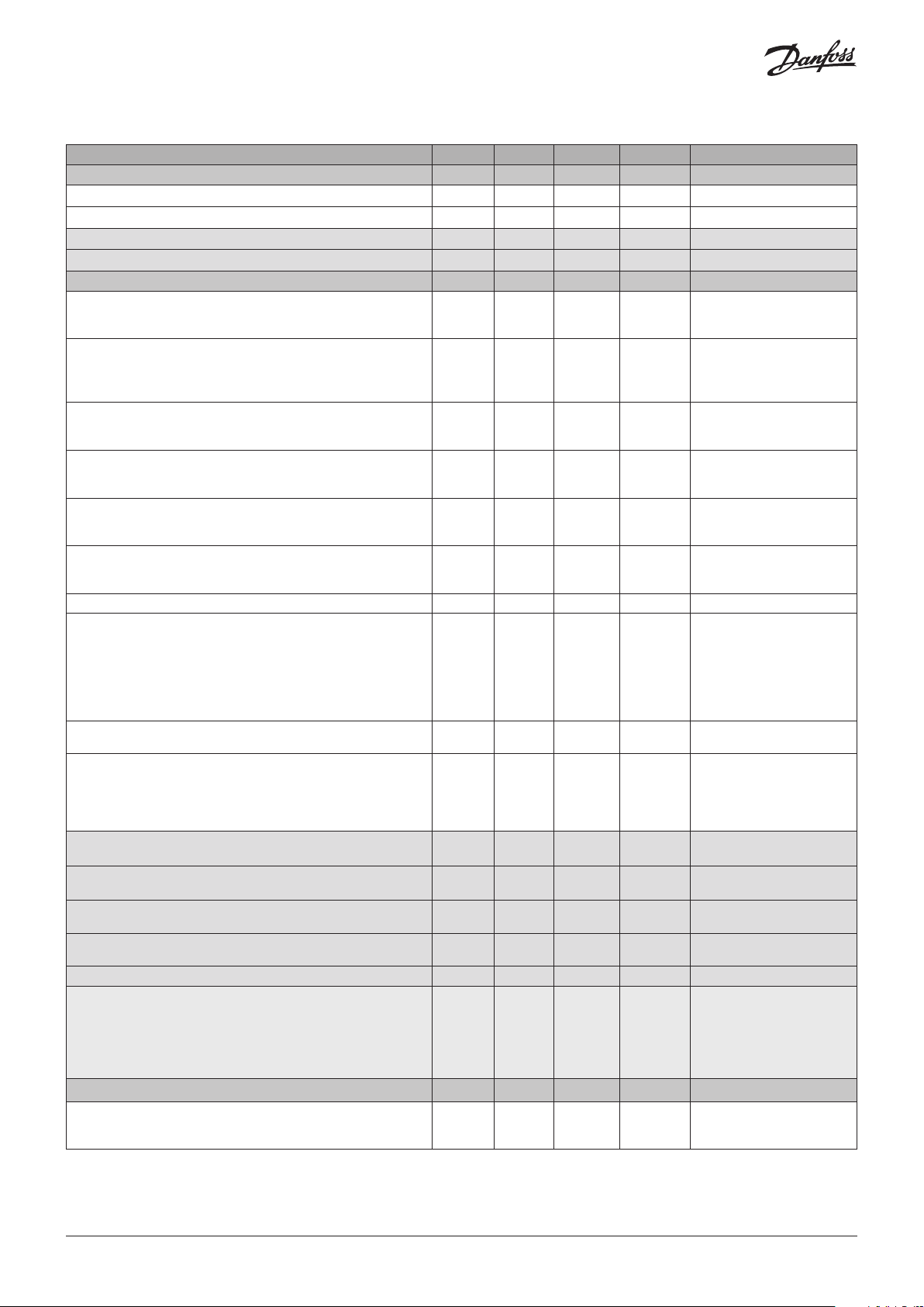
Menu Survey
Function Min. Max. Factory Unit AKM name
Gas level
Sensor 1 Actual gas level in % of range 0.0 100.0 - % Gas level %
Sensor 1 Actual gas level in ppm 0 FS1 - ppm Gas level ppm
Sensor 2 Actual gas level in % of range 0.0 100.0 - % 2: Gas level %
Sensor 2 Actual gas level in ppm 0 FS1 - ppm 2: Gas level ppm
Alarms Alarm settings
Indication of critical alarm (critical alarm of Gas1 or Gas2 active)
0: No active alarm(s)
1: Alarm(s) active
Common indication of both critical and warning alarm as well as
internal and maintenance alarms
0: No active alarm(s), warning(s) or errors
1: Alarm(s) or warning(s)) active
Gas 1 Critical limit in %.
Critical limit in % (0-100)
Gas 1 Critical limit in ppm
Critical limit in ppm; 0: Warning Signal deactivated
Gas 1 Warning limit in % (0-100) 0 100.0 HFC: 25
Gas 1 Warning limit ppm 0: Warning Signal deactivated 0.0 FS1 HFC: 500
High (critical and warning) alarm delay in seconds, if set to 0: no delay 0 600 0 sec. Alarm delay s
When set to 1, the Buzzer is reset (and the relays if defined: Relay rest
enable) to no alarm indication. When the alarm is reset or the
time-out duration is exceeded, the value is reset to 0.
Note: The alarm condition is not reset-only the output indication is
reset.
0: Alarm outputs not reset
1: Alarm outputs reset – Buzzer muted and relays reset if configured
Duration of alarm reset before automatic re-enable of alarm outputs.
A setting of 0 disables the ability to reset alarm.
Relay reset enables:
Relay reset with alarm acknowledge function
1= (default) Relays wil be reset if the alarm acknowledge function is
activated
0: Relays remain active until the alarm condition clears
Gas 2 Critical limit in %.
Critical limit in % (0-100)
Gas 2 Critical limit in ppm
Critical limit in ppm; 0: Warning Signal deactivated
Gas 2. Warning limit in % (0-100) 0 100.0 CO2: 25 % 2: Warn. limit %
0 1 - - GD alarm
0 1 - - Common errors
0.0 100.0 HFC: 25
CO2: 25
R290: 16
0 FS1 HFC: 500
CO2: 5000
R290: 800
CO2: 25
R290: 16
CO2: 5000
R290: 800
0 1 0 - Reset alarm
0 9999 300 sec. Reset alarm time
0 1 1 - Relay rst enable
0.0 100.0 CO2: 25 % 2: Crit. limit %
0 FS1 CO2: 5000 ppm 2: Crit. limit ppm
% Crit. limit %
ppm Crit. limit ppm
% Warn. limit %
ppm Warn. limit ppm
SW 1.1x
Gas 2. Warning limit ppm 0: Warning Signal deactivated 0.0 FS1 CO2: 5000 ppm 2: Warn. limit ppm
High (critical and warning) alarm delay in seconds, if set to 0: no delay 0 600 0 sec. 2: Alarm delay s
Configuration of relays for one or two rooms’ application mode.
1: One room with two sensors sharing the same warning relay and
critical relay
2: Two rooms with one sensor in each, and each sensor having a
critical alarm relay. In this mode, warning alarms activate as normal
on the LED indicator, hand-held Service Tool and on MODBUS.
Service
Status of the sensor's warm-up period:
0: Ready
1: Warming up one or more sensors
1
The max. alarm limit for CO2 is 16000 ppm / 80% of full scale. All other values equal the full scale range of the specific product.
© Danfoss | Climate Solutions | 2022.01
1 2 1 - 1:1 room (default)
2:2 rooms
0 1 - - DGS Warm-up
AN284527372096en-000301 | 5
Page 6
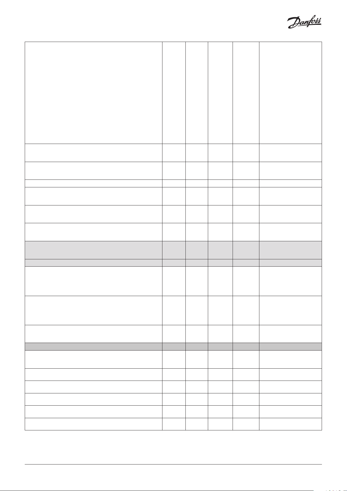
Readout the attached gas sensor type.
1 5 N - Sensor type
1: HFC grp 1
R1234ze, R454C, R1234yf
R1234yf, R454A, R455A, R452A
R454B, R513A
2: HFC grp 2
R407F, R416A, R417A
R407A, R422A, R427A
R449A, R437A, R134A
R438A, R422D
3: HFC grp 3
R448A, R125
R404A, R32
R507A, R434A
R410A, R452B
R407C, R143b
2
4: CO
5: Propane (R290)
Full scale range 0 32000 HFC: 2000
ppm Full scale ppm
CO2: 20000
R290: 5000
Gas 1 Days until next calibration 0 32000 HFC: 365
days Days till calib
CO2: 1825
R290: 182
Gas 1 Estimates how many days remaining for sensor 1 0 32000 - days Rem.life time
Status of the Critical Alarm Relay
0 1 - - Critical Relay
1: ON = no alarm signal, coil under power - normal
0: OFF = alarm signal, coil depowered, alarm situation
Status of the Warning Relay:
0 1 - - Warning Relay
0: OFF= inactive, no warning active
1: ON = active warning, coil under power
Status of the Buzzer:
0 1 - - Buzzer
0: inactive
1: active
Gas 2 Days until next calibration 0 32000 HFC: 365
days 2: Days til calib
CO2: 1825
R290: 182
Gas 2 Estimates how many days remaining for sensor 2 0 32000 - days 2: Rem.life time
Activates a mode which simulates an alarm. Buzzer, LED and relays all
0 1 0 - Test Mode
activate.
1:-> Test function - no alarm generation possible now
Automatically falls back to Off after 15 min.
0: back to normal mode
Analogue output max. scaling
0: zero to full scale (e.g sensor 0-2000 ppm) 0-2000 ppm will give
0-10 V)
0 1 HFC: 1
CO: 1
R290: 0
- AOmax = half FS
1: zero to half scale (e.g sensor 0-2000 ppm) 0-1000 ppm will give
0-10 V)
Analogue output min. value
0 1 0 - AOmin = 2V/4 mA
0: select 0-10 V or 0-20 mA output signal
1: select 2-10 V or 4-20 mA output signal
Alarms
Critical Limit alarm
0 1 - - Critical limit
0: OK
1: Alarm. Gas limit exceeded and delay expired
0: OK
0 1 - - Out of range
1: Fault. Out of range under test – over range or under range
0: OK
0 1 - - Wrong SensorType
1: Fault. Sensor and head failures
0: OK
0 1 - - Sensor removed
1: Fault. Sensor out or removed, or wrong sensor connected
0: OK
0 1 - - Calibrate sensor
1: Warning. Due for calibration
0: OK
0 1 - - Warning limit
1: Warning. Gas level above warning level and delay expired
6 | AN284527372096en-000301
© Danfoss | Climate Solutions | 2022.01
Page 7
Indication if the normal alarm function is inhibited or in normal
oss
80Z875
operation
0: Normal operation, i.e. alarms are created and cleared
1: Alarms inhibited, i.e. alarm status is not updated, e.g. due to DGS in
test mode
Critical Limit alarm
0: OK
1: Alarm. Gas limit exceeded and delay expired
0: OK
1: Fault. Out of range under test – over range or under range
0: OK
1: Fault. Sensor and Head failures
0: OK
1: Fault. Sensor out or removed, or wrong sensor connected
0: OK. Sensor not due for calibration
1: Warning. Due for calibration
0: OK
1: Warning. Gas level above warning level and delay expired
0 1 - - Alarm inhibited
0 1 - - 2: Criti. limit
0 1 - - 2: Out of range
0 1 - - 2: Wrong SensType
0 1 - - 2: Sens.removed
0 1 - - 2: Calibrate sens
0 1 - - 2: Warning limit
DGS troubleshooting
Symptom: Possible cause(s):
LED off • Check power supply. Check wiring.
• DGS MODBUS was possibly damaged in transit. Check by installing another DGS to confirm the
fault.
Green flashing • The sensor calibration interval has been exceeded or the sensor has reached the end of life. Carry
out calibration routine or replace with a new factory calibrated sensor.
Yellow • AO configured but not connected (only 0 – 20 mA output). Check wiring.
• Sensor type does not match DGS specification. Check gas type and measuring range.
• Sensor may be disconnected from printed circuit board. Check to see if the sensor is properly
connected.
• The sensor has been damaged and needs to be exchanged. Order replacement sensor from
Danfoss.
• Supply voltage out of range. Check power supply.
Yellow flashing • The DGS is set to service mode from the hand-held Service Tool. Change setting or await time-out
within 15 minutes.
Alarms in the absence of a leak • If you experience alarms in the absence of a leak, try setting an alarm delay.
• Perform a bump test to ensure proper operation.
The zero-measurement drifts The DGS-SC sensor technology is sensitive to the environment (temperature, moist, cleaning agents,
gases from trucks, etc). All ppm measurements below 75 ppm should be disregarded, i.e. no zeroadjustment made.
Power Conditions and Shielding Conceptions
Standalone DGS without
Modbus network
communication
DGS with Modbus
network communication
in combination with other
devices powered by the
same power supply
© Danfoss | Climate Solutions | 2022.01
Shield/screen is not required for standalone DGS with no connection to a RS-485 communication line.
However, it can be done as described in the next paragraph (Fig. 4).
It is strongly recommended to use direct current power supply when:
• more than 5 DGS units are powered by the same power supply
• the bus cable length is longer than 50 m for those powered units
It is moreover recommended to use class 2 power supply (see AK-PS 075)
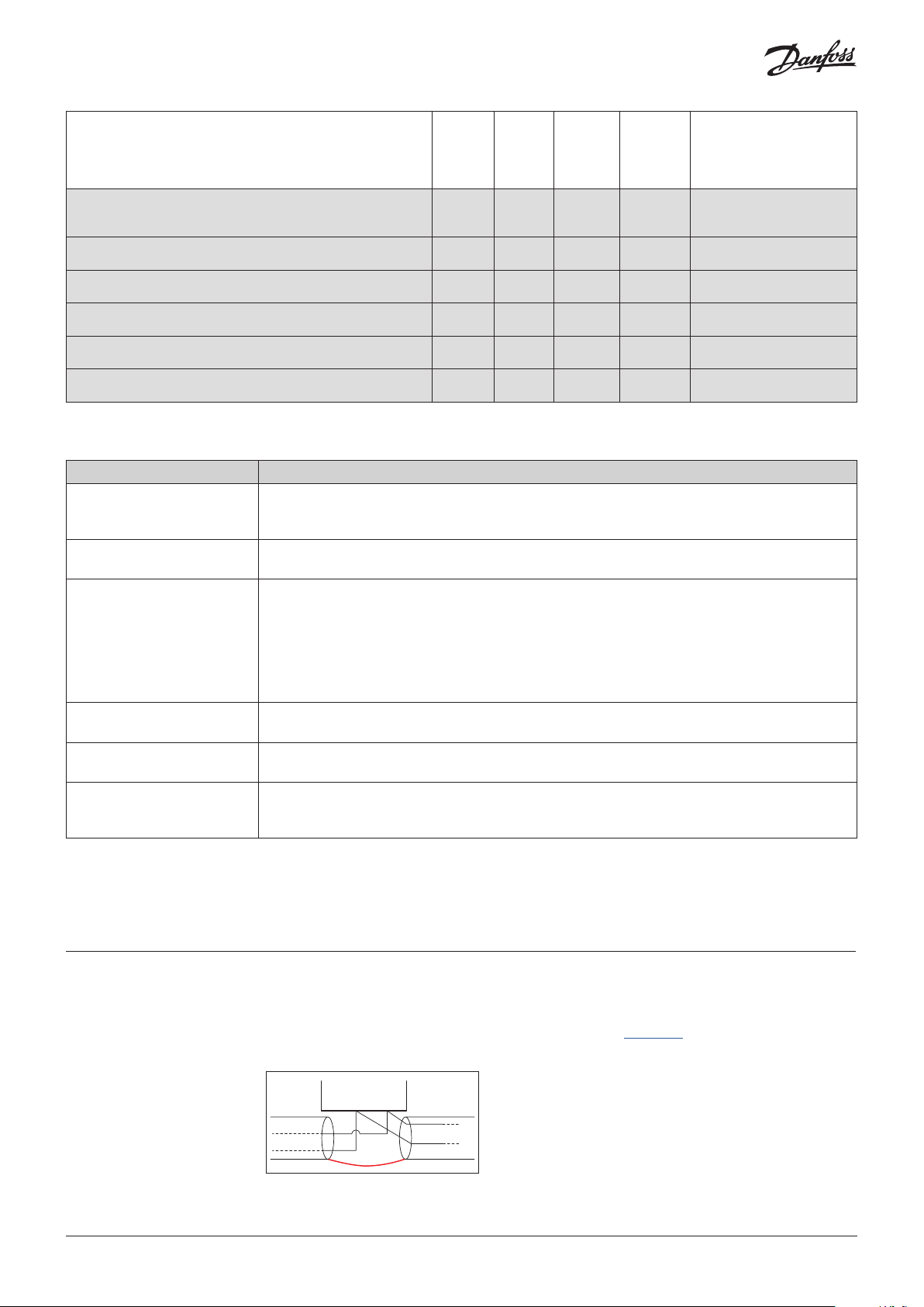
Make sure to not interrupt the shield when connecting A and B to the DGS (see Fig. 4).
–
A+B
Fig. 4: Loop trough
Danf
AN284527372096en-000301 | 7
Page 8

Shield
Busmaster
Busmaster
Danfoss
Modbus
device
Shld
A
B
DGS 1
#adr 10
A
B Gnd
+
DGS 2
#adr 11
A
B Gnd
+
1 KΩ
DGS n
#adr xx
A
B Gnd
+
AK-PS 075 power supply
+
–
Input 230 V
L
230 V
N
Fig. 5: Wiring diagram for system with one power supply
Ground potential difference between nodes of the RS485 network might affect the communication.
It is advised to connect a 1 KΩ 5% ¼ W resistor between the shield and the ground (X4.2) of any unit o
r group of units connected to the same power supply (Fig. 5).
Please refer to Literature No. AP363940176099.
Danfoss
80Z876
DGS with Modbus
network communication
in combination with other
devices powered by more
than one power supply
It is strongly recommended to use direct current power supply when:
• more than 5 DGS units are powered by the same power supply
• the bus cable length is longer than 50 m for those powered units
It is moreover recommended to use class 2 power supply (see AK-PS 075)
Make sure to not interrupt the shield when connecting A and B to the DGS (see Fig. 4).
1 KΩ
1 KΩ
Shield
DGS 1
#adr n1
A
B Gnd
Shield
DGS 1
#adr n11
A
B Gnd
AK-PS 075 power supply
+
+
+
DGS 2
#adr n2
A
B Gnd
DGS 2
#adr n12
A
B Gnd
+
+
DGS n
#adr nx
A
B Gnd
DGS n
#adr ny
A
B Gnd
+
–
AK-PS 075 power supply
+
+
–
L
230 V
N
L
230 V
N
L
230 V
N
Danfoss
Modbus
device
AK-SM
A
B
Shld
Busslave
L
230 V
N
Danfoss
Modbus
device
AK-CC
A
B
Shld
Fig. 6: Wiring diagram for system with multiple power supplies
Ground potential difference between nodes of the RS485 network might affect the communication.
It is advised to connect a 1 KΩ 5% ¼ W resistor between the shield and the ground (X4.2) of any unit
or group of units connected to the same power supply (Fig. 6).
Please refer to Literature No. AP363940176099.
Danfoss
80Z878
© Danfoss | Climate Solutions | 2022.01
Power supply and voltage alarm
The DGS device goes into voltage alarm when voltage exceeds certain limits.
The lower limit is 16 V.
The upper limit is 28 V, if DGS software version is lower than 1.2 or 33.3 V in all other cases.
When in the DGS the voltage alarm is active, in the System Manager the “Alarm inhibited” is raised.
AN284527372096en-000301 | 8
 Loading...