

Page 1

Installation Guide
DEVIreg™ Smart
Intelligent Electronic Timer Thermostat or Timer
Switch with Wi-Fi connectivity and App control
www.DEVI.com
Page 2

DEVIreg™ Smart
Table of Contents
1 Introduction . . . . . . . . . . . . . . . . . . . . . . 2
2 Technical Specications . . . . . . . . . . . . . . . 4
3 Safety Instructions . . . . . . . . . . . . . . . . . . 6
4 Mounting Instructions . . . . . . . . . . . . . . . . 8
5 Display Symbols . . . . . . . . . . . . . . . . . . . 13
6 Configuring . . . . . . . . . . . . . . . . . . . . . . 19
7 Settings . . . . . . . . . . . . . . . . . . . . . . . . 20
8 Warranty. . . . . . . . . . . . . . . . . . . . . . . . 23
9 Radio Equipment Directive . . . . . . . . . . . . 24
10 Disposal Instruction . . . . . . . . . . . . . . . . 25
1 Introduction
DEVIreg™ Smart is an electronic programmable timer
thermostat used for controlling electrical oor heating
elements. The thermostat is designed for xed installation
only and can be used for both direct heating of the entire
room and for comfort heating of the oor. Among others,
the thermostat has the following features:
• A touchscreen display with light.
• An easy-to-follow menu-driven programming and
operation (requires an app).
Installation Guide2
Page 3

DEVIreg™ Smart
• An installation wizard with room/oor type-specic
setup (requires an app).
• Support for multiple frame systems.
• Compatible with several 3rd party NTC sensors.
• Thermostat settings can be specied before installation and imported to the thermostat using a webgenerated code (For DEVIreg™ Touch), or copied
from a thermostat in a similar installation. This
includes DEVIreg™ Touch thermostats.
• Smart access via app to thermostat settings after
installation, for easy access, setup or remote troubleshooting. Thermostat/timer will continuously be
updated with newest version of software.
• DEVIreg™ Smart can be used as a switch for On/O
systems
Regarding Connectivity:
• 10 smart devices (like Smartphone or Tablet) can be
connected to 1 thermostat/switch.
• 2 smart devices can be in contact with the thermostat/switch at the same time.
DEVIREG™ SMART REQUIRES WORKING Wi-Fi
TO FUNCTION .
3Installation Guide
Page 4

DEVIreg™ Smart
More information on this product can also be found at:
devismart.com
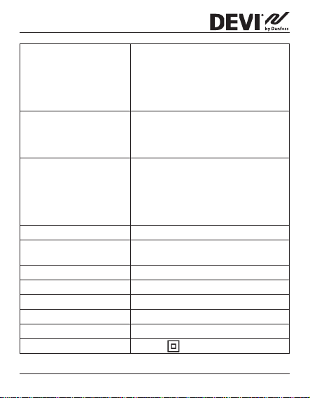
2 Technical Specications
Operation voltage 220–240 V~, 50/60 Hz
Standby power
consumption
Relay:
Resistive load
Inductive load
Sensing units* NTC 6,8 kOhm at 25°C
Sensing values*:
(Default NTC 15 K)
0 °C
20 °C
50 °C
Control* PWM (Pulse Wide Modulation)
Ambient temperature 0°C to 30°C
Frost protection
temperature*
Max. 0,40 W
Max. 16 A / 3680 W @ 230 V
Max. 1 A cos φ= 0,3
NTC 10 kOhm at 25°C
NTC 12 kOhm at 25°C
NTC 15 kOhm at 25°C (Default)
NTC 33 kOhm at 25°C
NTC 47 kOhm at 25°C
42 kOhm
18 kOhm
6 kOhm
5°C to 9°C (default 5°C)
Installation Guide4
Page 5
DEVIreg™ Smart
Temperature range* Room temperature: 5°C to 35°C.
Sensor failure monitoring* The thermostat has a built-in
Timer functions 2 periods per day for DEVIweb™.
Cable specication max. 1x4 mm
Ball pressure test temperature
Floor temperature: 5°C to 45°C.
Max. oor: 20°C to 35°C (if unrecoverable seal is broken then up to 45°C).
Min. oor: 10°C to 35°C, only with
combination of room and oor sensor.
monitoring circuit, which will switch
o the heating if the sensor is
disconnected or short-circuited.
5 periods per day for DEVIsmart App.
All clock/date/schedule settings are
updated from the cloud.
Set-point resolution of timer is
30minutes.
2
75°C
Pollution degree 2 (domestic use)
Controller type 1C
Software class A
Storage temperature -20°C to +65°C
IP class 21
Protection class Class II -
5Installation Guide
Page 6
DEVIreg™ Smart
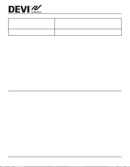
Dimensions 85 x 85 x 20-24 mm
Weight 127 g
* not relevant for switch function
(in-wall depth: 22 mm)
Electrical safety and Electro-Magnetic Compatibility
for this product is covered by the compliance with the
EN/IECStandard “Automatic electrical controls for household and similar use”:
• EN/IEC 60730-1 (general)
• EN/IEC 60730-2-7 (timer)
• EN/IEC 60730-2-9 (thermostat)
3 Safety Instructions
Make sure the mains supply to the thermostat/switch is
turned o before installation.
Important: When the thermostat is used to control a
oor heating element in connection with a wooden oor
or similar material, always use a oor sensor and never set
the maximum oor temperature to more than 35°C.
Please also note the following:
• The installation of the thermostat
by an authorized and qualied installer according to
local regulations.
/switch
must be done
Installation Guide6
Page 7

DEVIreg™ Smart
• The thermostat
/switch
must be connected to a power
supply via an all-pole disconnection switch.
• Always connect the thermostat
/switch
to continuous
power supply.
• Do not expose the thermostat
/switch
to moisture,
water, dust, and excessive heat.
• This thermostat
/switch
can be used by children aged
from 8 years and above and persons with reduced
physical, sensory or mental capabilities or lack of experience and knowledge, if they have been given supervision or instruction concerning use of the appliance in
a safe way and understand the hazards involved, by a
person responsible for their safety.
• DEVIreg™ Smart can modied to work as a timer on/
o switch by downloading new software with new
functionality.
• Children should be supervised to ensure that they do
not play with the thermostat
/switch
.
• Switch is designed for permanent operation.
• Not for uorescent lamps and lament lamps.
• Cleaning and user maintenance shall not be made by
children without supervision.
• Updating to timer switch function may take up to
1hour. Same time should be expected if function is to
be rolled back to thermostat functionality.
7Installation Guide
Page 8

DEVIreg™ Smart
4 Mounting Instructions
Please observe the following placement guidelines:
Place the thermostat at a suitable height on the wall
(typically 80–170 cm). Switch can be placed on free
area on the wall.
The thermostat/switch should not be placed in wet
rooms. Thermostat/switch must be placed outside
zone 2. Place it in an adjacent room and use oor
sensor only. Always place the thermostat/switch
according to local regulation on IP classes.
Do not place the thermostat on the inner side of a
poorly insulated exterior wall.
Always install the thermostat at least 50 cm from
windows and doors, due to draft, when using regulation
in: oor and room mode or room alone mode.
Do not place the thermostat in a way that it will be
exposed to direct sunlight.
Installation Guide8
Page 9
DEVIreg™ Smart
12
≥
Note for thermostat: A oor sensor is recommended in all oor heating applications and mandatory
to thin mats and under wooden oors to reduce the
risk of over-heating the oor.
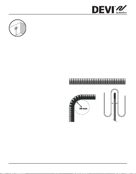
• Place the oor sensor in a protecting plastic conduit
in the oor construction in an appropriate place,
where the oor is not exposed to sunlight or draft
from door openings.
• Equally distant and
>2 cm from the
heating cables on
both sides.
• The conduit should
be ush with the
oor surface, countersink the conduit
if necessary and
possible.
• Route the conduit to the connection box.
• The bending radius of the conduit must be min 50 mm.
9Installation Guide
Page 10

DEVIreg™ Smart
Follow the steps below to mount the thermostat/switch:
1. Unpack thermostat/switch.
2.1. Connect the thermostat according to the connection
diagram.
L
L
O
The screen of the heating
cable must be connected to
the earth conductor of the
power supply cable by using
a separate connector.
NTC
Sensor
Danfoss A/S
Nordborgvej 81
6430 Nordborg
Denmark
Standby maximum 0.4 Watt
A
D
Maximum
Load 16 (1) A
N
Mains
220-240V~
50-60 Hz
IP21
T30
O
A
NLL
D
Note: Always install the oor sensor in a conduit in
the oor.
L
L
O
2.2. Connect the switch according to the connection
diagram.
NTC
Danfoss A/S
Nordborgvej 81
6430 Nordborg
Denmark
Standby maximum 0.4 Watt
A
D
Maximum
Load 16 (1) A
N
Mains
220-240V~
50-60 Hz
IP21
T30
O
A
NLL
D
3. Fasten the thermostat/switch rmly to a ush
mounted wall box or an exterior wall box by driving
Installation Guide10
Page 11

DEVIreg™ Smart
the screws through the holes in each side of the
thermostat/switch.
4. Add the frame before assembling of top part to the snap
locks/bottom part.
5. Click the front part module in
place. Pay attention, in relation
to the female header, in not to
bending the connectors. Press
carefully until the frame is xed
against the rubber gasket.
11Installation Guide
Page 12

DEVIreg™ Smart
Important: Do NOT press in the center of the display screen.
When mounting and reassembling the thermostat/switch.
Press your ngers under the top of the front part and pull
toward you until it releases from the snap lock:
To ensure that the batteries are fully charged, the thermostat/switch shall be connected to main supply for
minimum 15 hours.
All other settings are stored permanently.
Installation Guide12
Page 13

DEVIreg™ Smart
5 Display Symbols
Top part main functionalities are to support user interface
through display and hold all the controller logic.
Display main functionalities are to show the current status
of the thermostat/switch and recognize the user actions
from the buttons. Display consists of dierent buttons,
numbers and symbols.
Thermostat Switch
1
2
4
3
13Installation Guide
Page 14

DEVIreg™ Smart
Nr. Type Description
1 Button/Symbol Control button
2 Button/Symbol Arrow Up button
3 Button/Symbol Arrow Down button
4 Symbol Thermostat function: 3 digit 7 seg-
ment numbers with comma separator
for temperature indication. Timer
switch function: “On”/”O” text.
Symbol indications
Indication Mode/State Description
Blue - blinking Access Point
Blue Access Point
Red - blinking Fault state Displays Error code
Red - slow
pulsing
Green - constant Active Mode Thermostat/switch active and
Mode
Mode
Active Mode Indicating heating the oor
Thermostat/switch ready for
set-up
Smart phone connected
directly to thermostat/switch
for set-up
(Relay on)
connected to Wi-Fi (Relay o)
Installation Guide14
Page 15

DEVIreg™ Smart
Green – blinking Active Mode
Arrows –
blinking rapidly
when touched
& Access
Point Mode
Active Mode Safety lock is on
Thermostat/switch waiting for
conrmation of action
Interaction directly on thermostat
Function Button Description
Turn
thermostat/
switch on
Turn
thermostat/
switch o
Adjust setpoint
1. Touch any button
2. Touch control button (1)
1. Touch any button
2. Touch and hold
control button (1)
Up (2) Overrule timer and
Down (3) Overrule timer and
Thermostat/switch
turn on and display
temperature or On/O
states
Thermostat/switch
display will turn on
Thermostat switch
count down and switch
o
switch on/temporary
set point
switch o/temporary
set point
15Installation Guide
Page 16
DEVIreg™ Smart
Frost protection
Safety lock Touch and hold Up (2)
Factory
restore
Away mode Touch and hold
Touch and hold Control (1) for 1 sec.
+ Down (3) for 3 sec.
Touch and hold
Control (1) + Up (2)
for 5 sec.
After that touch
Control (1) again to
conrm
Control (1) for 1 sec. to
deactivate Away mode
Deactivate frost protection
Activate/Deactivate
safety lock
Activates factory
restore state
Activate/Deactivate
Away/Vacation mode
Error codes
When the error occurs and is resolved, the thermostat, in
some cases, will require a restart to start heating again.
Installation Guide16
Page 17

DEVIreg™ Smart
Error
type
Floor
Sensor
disconnected
Floor
Sensor
shortcircuited
Thermostat overheated
Unrecoverable
error
Nr. Description Solution Need restart
E1 Connection
to sensor is
lost
E2 Sensor short-
circuited
E3 Thermostat
is overheated, heating is
turned o
E4 Room
temperature
sensor value
too high or
too low
Contact
service
Contact
service
Wait until
thermostat cools
down
Contact
service
The thermostat
requires a restart
to operate again.
The thermostat
requires a restart
to operate again.
The thermostat
requires no
restart, but will
start heating
when the
temperature is
lowered
The thermostat
requires a restart
to operate again.
17Installation Guide
Page 18

Communication Error Codes
DEVIreg™ Smart
Communication
error
Wrong SSID or
password
No IP address C2 STA - connection acquired, no IP
No internet connection
Nr. Description
C1 STA trying to connect to the AP
yet, waiting for conguration data.
C3 STA connected and has an IP from
DHCP server.
Installation Guide18
Page 19
DEVIreg™ Smart
6 Configuring
Download App
Download the DEVIsmart™ app from App Store
or Google Play or at devismart.com.
Find Wi-Fi name and password for the Wi-Fi
network, that you would like to connect your
thermostat/switch to. If in doubt contact network administrator or internet service provider.
Identify your oor sensor type ( in kOhm).
Identify your installed output (in W), from
label on the heating element/equipment.
Power on the thermostat, and it will show
“-“ in the display. Then it is ready to be congured using your iPhone and Android device.
Open the DEVIsmart™ App. Follow instructions and setup ow in the App.
DEVIreg™ Smart indication
The DEVIreg™ Smart shows “–” indicating that power is
ON, but still need to be congured.
19Installation Guide
Page 20
7 Settings
DEVIreg™ Smart
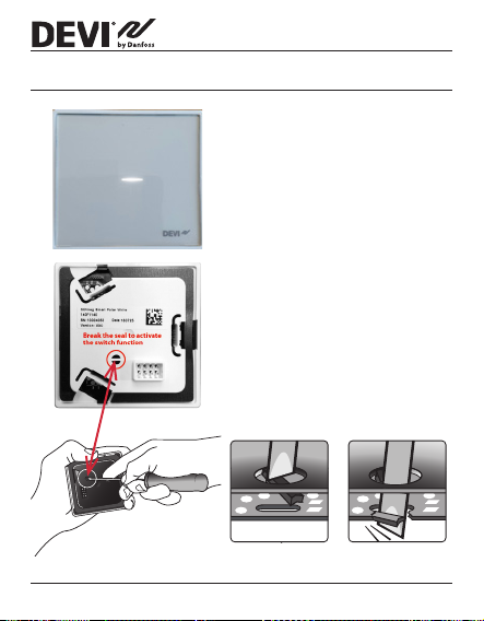
IMPORTANT DURING
THERMOSTAT SET-UP
Select whether only a oor sensor or a combination of room
and oor sensor should be used.
A “room only” option is also
available, but requires that you
have to break the small plastic
seal and the seal in the print
board below, on the back of
the display module, e.g. using
a screwdriver; reset is needed;
it will be possible to set the
Installation Guide20
Page 21

DEVIreg™ Smart
maximum oor temperature up to 45 °C. Furthermore, it
will be possible to use only a room sensor. However, this
option is not recommended due to an increased risk of
overheating the oor.
IMPORTANT: When the thermostat is used to control a
oor heating element in connection with a wooden oor
or similar material, always use a oor sensor and never set
the maximum oor temperature to more than 35°C.
Note: Please contact the oor supplier before changing the
maximum oor temperature and be aware of the following:
• The oor temperature is measured there, where the
sensor is placed.
• The temperature of the bottom of a wooden oor
can be up to 10˚C higher than the top.
• Floor manufactures often specify the max. temperature on the top surface of the oor.
21Installation Guide
Page 22
DEVIreg™ Smart
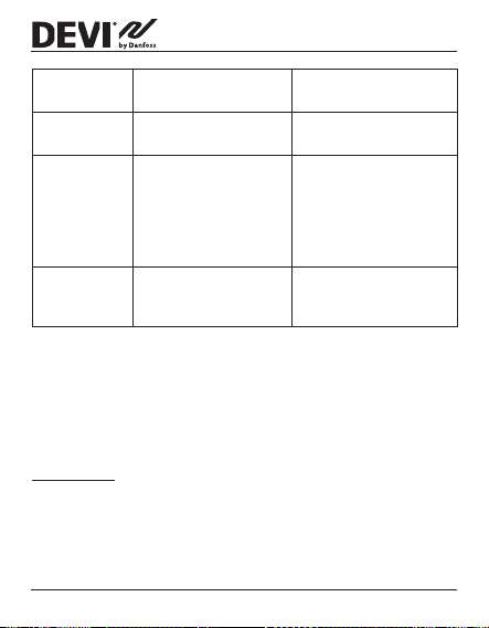
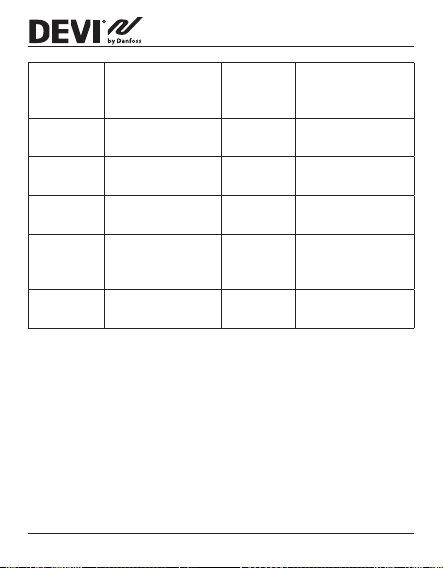
Thermal
resistance
[m2K/ W]
0,05 8 mm HDF based
0,10 14 mm beech
0,13 22 mm solid oak
< 0,17 Max. carpet thick-
0,18 22 mm solid r
Examples of
ooring
laminate
parquet
plank
ness suitable for
oor heating
planks
Details
kg/m
> 800 28°C
650 – 800 31°C
> 800 32°C
acc. to
EN 1307
450 – 650 35°C
Approximate set-
3
ting for 25°C oor
temperature
34°C
IMPORTANT DURING SWITCH SETUP
To use the switch function, it requires that you have to
break the small seals on the back of the display module,
e.g. using a screwdriver, by the same actions as described
for thermostat.
Installation Guide22
Page 23
DEVIreg™ Smart
8 Warranty
The products will, in the event of a fault that can be tracked
back to a manufacturing defect in the DEVI product, be
repaired or replaced free of charge. To apply for this warranty the installation must be performed by an authorized
installer and the warranty certicate has to be stamped,
signed and provided. For more details read our warranty
terms and conditions.
23Installation Guide
Page 24

DEVIreg™ Smart
9 Radio Equipment Directive
SIMPLIFIED EU DECLARATION OF CONFORMITY
The simplied EU declaration of conformity referred to in
article 10(9) shall be provided as follows:
Hereby, Danfoss A/S declares that the radio equipment
type i.e. DEVIreg Smart is in compliance with Directive
2014/53/EU.
The full text of the EU declaration of conformity is available at the following internet address: devi.danfoss.com
Installation Guide24
Page 25
DEVIreg™ Smart
10 Disposal Instruction
25Installation Guide
Page 26

DEVIreg™ Smart
Installation Guide26
Page 27

DEVIreg™ Smart
27Installation Guide
Page 28

DEVIreg™ Smart
Danfoss
produc
Al
Danfoss A/S
DEVI • devi.com • +45 7488 8500 • E-Mail: EH@danf
can accept no responsibility for possible errors in catalogues, brochures and other printed material. Danfoss reserves the right to alter its products without notice. This also applies to
ts already on order provided that such alterations can be made without subsequential changes being necessary in specifications already agreed.
l trademarks in this material are property of the respective companies. Danfoss and all Danfoss logotypes are trademarks of Danfoss A/S. All rights reserved.
oss.com
Produced by Danfoss © 03/202008096265 & AN335651484034en-000101
 Loading...