

DEVIreg™ Hotwater
EN
Installation and User Guide
DEVIreg™ Hotwater
DIN-rail programmable controller for hotwater maintenance
Intelligent solutions
with lasting effect
Visit devi.com


Installation and User Guide DEVIreg™ Hotwater
Table of content
1 Introduction .......................................................................4
2 Safety Instructions .................................................................5
3 Mounting Instructions .............................................................5
4 User Manual .......................................................................6
4.1 General use ...................................................................6
Buttons ..................................................................................6
Display ...................................................................................6
Main Screen view (default) ................................................................7
Heater sub-screen view ...................................................................7
Setup wizard. . . . . . . . . . . . . . . . . . . . . . . . . . . . . . . . . . . . . . . . . . . . . . . . . . . . . . . . . . . . . . . . . . . . . . . . . . . . . . 8
First start-up ..............................................................................9
Sub-menu Alarm ........................................................................10
Sub-menu Service .......................................................................10
Function Setup Wizard ...................................................................11
Sub-menu (H1-H4) .......................................................................12
Sub-menu Disinfection schedule .........................................................14
Alarms view .............................................................................15
Main menu ..............................................................................15
4.2 Language setting ........................................................... 16
4.3 Date and Time settings ......................................................16
4.4 BMS settings ................................................................ 16
5 Connection diagram ............................................................. 17
Connection scheme DEVIreg™ Hotwater .................................................17
6 Technical Specifications .......................................................... 18
6.1 Technical data. . . . . . . . . . . . . . . . . . . . . . . . . . . . . . . . . . . . . . . . . . . . . . . . . . . . . . . . . . . . . . . 18
6.2 Dimensions ................................................................. 19
7 Disposal Instruction .............................................................. 20
FEC | Produced by Danfoss © 3
Installation and User Guide DEVIreg™ Hotwater
1 Introduction
DEVIreg™ Hotwater is a 4 channel electronic programmable controller. 3 additional chan-
cels are not used in this constellation. The device is DIN-rail mountable and is used for
control of Devi Hotwatt cables. Every channel (4) can be individually set up, this will allow
for 4 different temperatures and disinfection schedules.
Universal analog channels’ inputs can be selected via software between 7 types of temperature
sensors including NTC 15 kOhm at 25 °C. The controller has a LCD display, Modbus RS-485
serial interface and 110/230 V AC power supply. Voltage to sensors is SELV.
DEVIreg™ Hotwater has 8 control relays – 2 sets of max. 10 A and 6 sets of max. 6 A; For this
specific application 2, 10A and 2, 6A relays are used. Relay control functions can be set to
Hot-water maintenance and legionella control of a hot-water system by use of applicable
heating cables. Additionally, relay contacts are not connected to a voltage source inside the
controller, and can be used for control systems with any voltage up to 250 V AC.
Hardware of DEVIreg™ Hotwater is based on the Danfoss controller type MCX08M2,
art. no. 080G0307, but is customized with special software.
The product complies with the EN/IEC Standard “Automatic electrical controls for household and similar use”:
• EN/IEC 60730-1 (general)
• EN/IEC 60730-2-9 (thermostat)
More information on this product can also be found at: devi.com
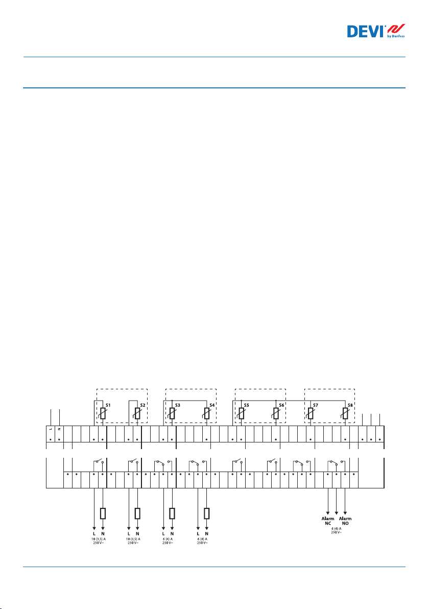
Connection scheme DEVIreg™ Hotwater
Power
110/230 V AC
COM
DI 1-4
DI 1
S - temperature Sensor;
H - Heating element.
AI 1
COM
C 1
NO 1
H1 H2 H3 H4
AI 2
COM
DI 2
C 2
NO 2
DI 3
for H2 for H3for H1
AI 3
COM
AI 3-4
NC 3
C 3
NO 3
AI 4
DI 4
NC 4
C 4
NO 4
AI 5
COM
AI 5-8
DI 5
C 5
NO 5
AI 6
DI 6
C 6
NO 6
DI 7
for H4
AI 7
NC 7
C 7
NO 7
NC 8
DI 8
RS485
(Modbus)
D -
D +
AI 8
C 8
NO 8
GND
RS485
COM
DI 5-8
FEC | Produced by Danfoss ©4

Installation and User Guide DEVIreg™ Hotwater
2 Safety Instructions
Make sure the mains supply to the controller is turned off before installation.
Please also note the following:
• The installation of the controller must be done by an authorized and qualified installer
according to local regulations.
• The controller must be connected to a power supply via an all-pole disconnection switch.
• Always connect the controller to continuous power supply.
• Do not expose the controller to moisture, water, dust and excessive heat.
Note: Product is designed for Over Voltage Category II. When used, installation must be
equipped with transient protection.
3 Mounting Instructions
Please observe the following placement guidelines:
Install the thermostat in an electric cabinet with DIN rail attachment or a separate DIN
attachment according to local regulation on IP classes.
Do not place the thermostat in a way that will expose the controller to direct sunlight.
Follow the steps below to mount the thermostat:
1. Click the thermostat on the DIN rail attachment.
2. Connect the thermostat according to the connection diagram, see page 4.
3. The screen of the heating cable must be connected to the earth conductor of the
power supply cable by using a separate connector.
4. Turn on the power supply.
Note: Always install the sensors at assumed hottest and coldest locations on the respective pipe, and in direct contact with the pipe (2 sensors pr. heating circuit)
FEC | Produced by Danfoss © 5

Installation and User Guide DEVIreg™ Hotwater
4 User Manual
4.1 General use
The DEVIreg™ Hotwater is operated via 6 physical buttons to the right of the LCD-display.
Buttons
The functions of the 4 operated buttons are:
Up, Down
Left, Right
Escape
Enter Confirm / select / go to the Main menu
Display
The DEVIreg™ Hotwater can simultaneously control up to 4 different systems
are referred as H1, H2, H3 and H4 (short for Heater).
The DEVIreg™ Hotwater provides the user with an opportunity to view the current status
of the all systems. This status is allways shown on the main screen.
Next menu entry / next line / next setting parameter
Shows additional information
Escape return to previous level of menu / show Alarm
screen
. These 4 systems
FEC | Produced by Danfoss ©6
Installation and User Guide DEVIreg™ Hotwater
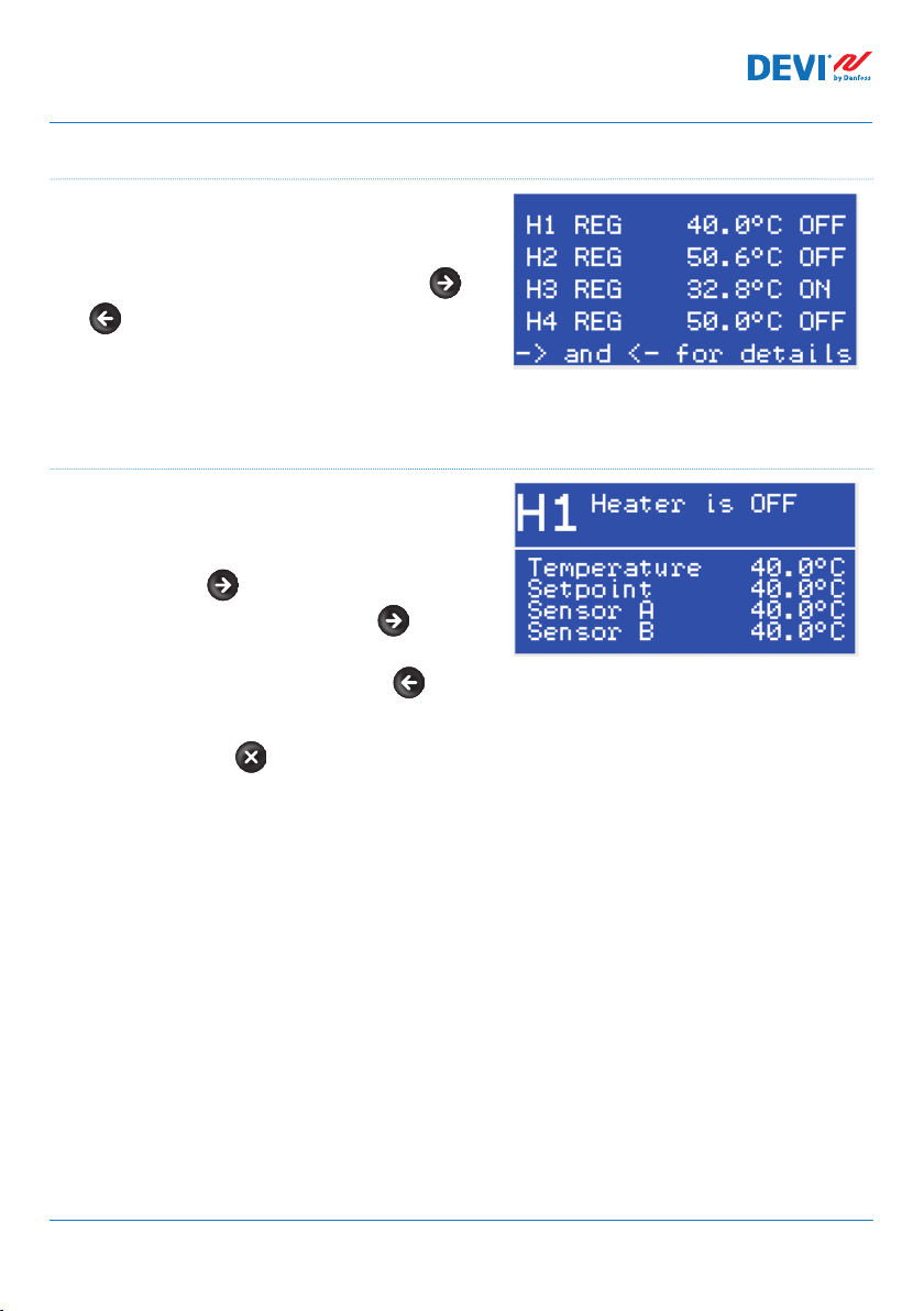
Main Screen view (default)
The Main Screen is the main window
appearing when the controller is powered. This
screen displays an overview of data from the
different heaters. (H1-H4) by pressing the
and more detailed information can be ob-
tained from the respective heaters sub screen.
This view provides the user with an overview of
all systems, however with limited information.
Heater sub-screen view
These screens give to user quick and more
detailed information about settings and status
of each heater.
Just press button on the Main Screen of controller and H1 data will appear, press again
- and you'll see H2 data, and so on. To progress
reversly through this menu please use .
To exit from sub-screens view and return to the
Main Screen - press 1 time.
FEC | Produced by Danfoss © 7
Installation and User Guide DEVIreg™ Hotwater
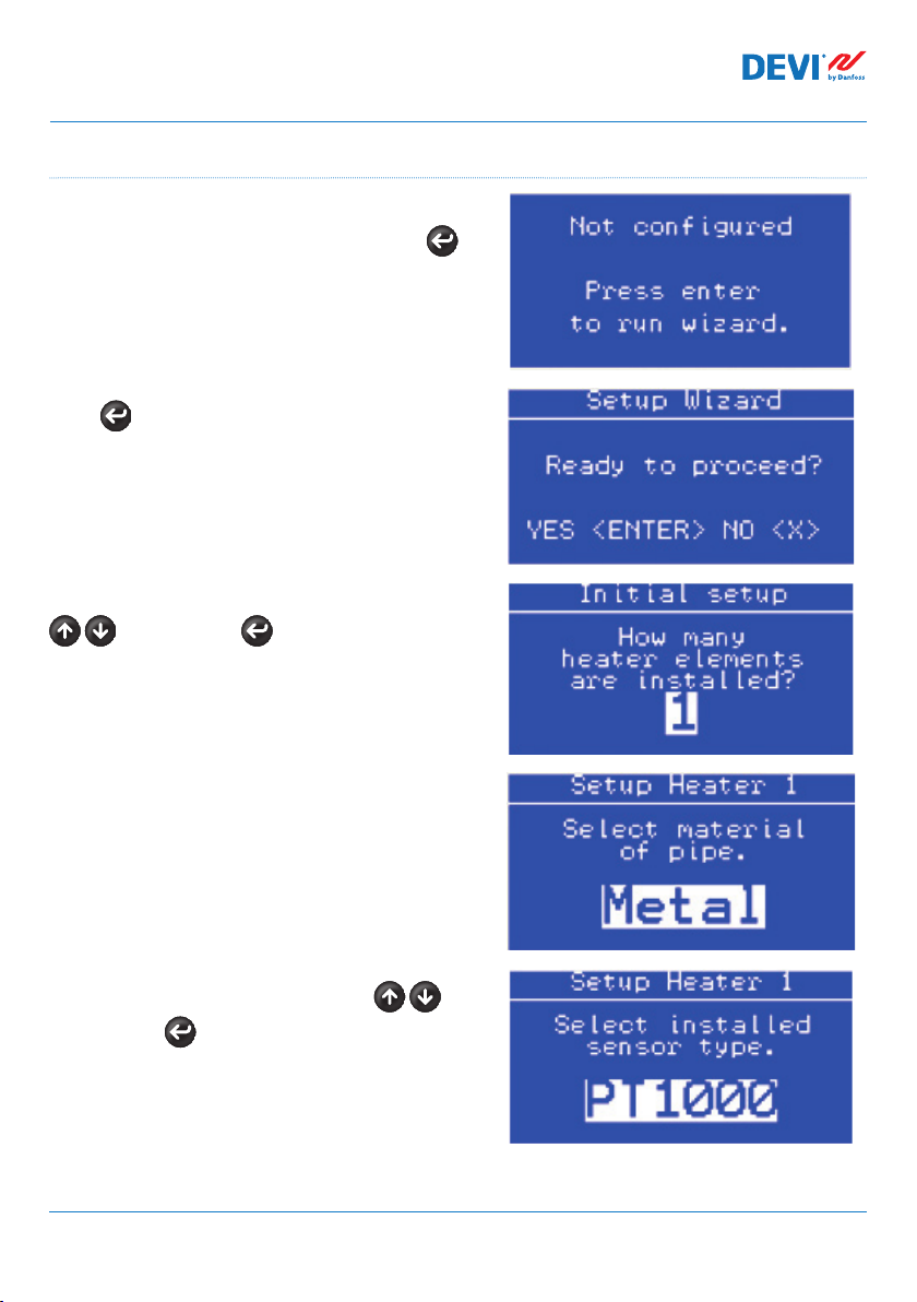
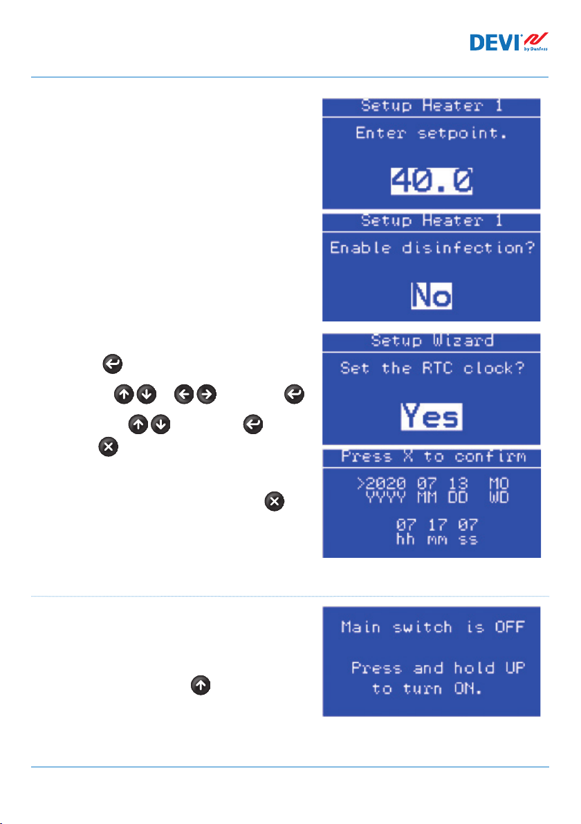
Setup wizard
On the first power on of the device, the device
will ask to run the wizard to do this press
Press once more to proceed into the setup.
The device will ask for the amount heaters use
to select and to accept.
The device will now ask for the details of each
heater in the following pattern
- Pipe material
- Sensor type
- Temperature setpoint
- Enable disinfection
All mentioned can be selected with and
accepted by .
FEC | Produced by Danfoss ©8
Installation and User Guide DEVIreg™ Hotwater
If multiple heaters are entered, this exact procedure will repeat till all information is filled for
all heaters.
The final step in the wizard is the RTC (Real Time
Clock) press
Navigate with or select with
Manipulate with accept with or
return with
Once time and date are set confirm with
First start-up
Ensure everything is correctly connected and
securely fixed.
Please check this now.
Once verified press and hold (approx. 3-5 sec.)
to turn on the device.
T
he device will now commence normal operation.
FEC | Produced by Danfoss © 9

Installation and User Guide DEVIreg™ Hotwater
Sub-menu Alarm
The structure in this Sub-menu is navigated like
the main menu.
Active alarms: display of the currently active
alarms and is to navigate like Alarm view.
Having an active alarm will activate alarm
relay. Alarms will be retained till reset has been
performed.
Reset Alarms: Reset all alarms by pressing
Log history: display previous alarms in a list
with date and timestamp. This is navigated like
Alarm view.
Clear log history: clears the log history permanently by pressing
Sub-menu Service
The structure in this Sub-menu is navigated like
the main menu.
System: contains a system submenu for professional users containing (Yxx) parameters.
Additionally this menu should under normal
circumstances not be used.
This menu will change according to the user
level password entered in Login.
Relay counters:
Displays the number of relay ON/OFF switching’s performed by each relay.
Software info:
Displays the installed software version.
Device info:
Displays serial number, product code and BIOS version
FEC | Produced by Danfoss ©10

Installation and User Guide DEVIreg™ Hotwater
RTC setup:
Setup of the real time clock, this is to navigate like explained in setup wizard step RTC.
Login:
Enables a password to be input and is to be navigated with and select
with
Configuration:
Contains buzzer activation time, delay for alarm activation and alarm state when device
is OFF.
Serial settings:
Contains Modbus/CAN serial address, Modbus serial baudrate and Modbus serial settings
Language:
The structure in this Sub-menu is navigated like the main menu.
Contains the different language variants.
Function Setup Wizard
This function will reset the device into the Setup
Wizard.
Yes with or NO with
FEC | Produced by Danfoss © 11

Installation and User Guide DEVIreg™ Hotwater
Sub-menu (H1-H4)
The structure in this Sub-menu is navigated like the main menu.
Sensor type:
to select correct type and to confirm.
Be aware that 2 sensors must be used for each heater circuit (H1-H4) and that these must
be the same type.
-PT1000
-NTC16K (NTC16.8K)
-NTC100 (NTC100K)
-NTC2K
-NTC5K
-NTC10K
-NTC15K (Std. DEVI sensor)
Has no default value as this must be set in setup wizard. Please refer to the sensors maximum
and minimum temperatures to ensure safe operation of the system.
Setpoint:
Settable with to select and to confirm.
Settable temperature setpoint (desired maintained temperature) between 20.0-80.0°C
(20-60.0°C on plastic pipe).
Has no default value as this must be set in setup wizard.
Hysteresis:
Settable with to select and to confirm.
Settable between 1.0-10.0K
Defaults to 2.0K
High temperature:
Settable with to select and to confirm.
Settable between 20.0-90.0K
Defaults to Setpoint+Hysteresis+5K
Not settable below setpoint
FEC | Produced by Danfoss ©12

Installation and User Guide DEVIreg™ Hotwater
Alarm delay:
Settable with to select and to confirm.
Temperature alarm delay
Settable between 10-240s
Defaults to 10s
Sensor weighting:
Settable with to select and to confirm.
Weighting the impact of the 2 sensors on the heater regulation.
0% means that the regulation is made on basis of sensor A only 100% meaning sensor B only,
thus 50% is the mean between sensor A and B.
Settable between 0-100%
Defaults to 50%
Disinfection temp:
Settable with to select and to confirm.
Settable between 55-80.0°C
Defaults to 55°C
Pipe material:
Settable with to select and to confirm.
This parameter will have impact on the maximum settable temperatures.
Can be set to metal or plastic.
Has no default value as this must be set in setup wizard
Disinfection alarm temperature:
Settable with to select and to confirm.
This parameter will have impact on the alarm temperature for disinfection temperatures.
Defaults to 65°C
FEC | Produced by Danfoss © 13

Installation and User Guide DEVIreg™ Hotwater
Maximum rising time:
Settable with to select and to confirm.
This parameter will have impact on when the alarm will be triggered due to, too low
temperature (setpoint not reached).
Defaults to 120 minutes.
Sub-menu Disinfection schedule
The structure in this Sub-menu is navigated like
the main menu.
(H1-H4) Schedule:
Press to go to next parameter and to
cancel.
Settable with to select and to
confirm.
Defaults to Sunday at 02:00.
(H1-H4) Manual start:
Starts the Disinfection procedure manually by
pressing
FEC | Produced by Danfoss ©14

Installation and User Guide DEVIreg™ Hotwater
Temperature time table:
Temperature of
disinfection [C°]
55 2h 00 minutes
56 1h 20 minutes
57 1h 00 minutes
58 0h 50 minutes
59 0h 45minutes
60 0h 40 minutes
61 0h 35 minutes
62 0h 30minutes
63 0h 28 minutes
64 0h 27 minutes
65 0h 26minutes
Disinfection time
Temperature of
disinfection [C°]
66 0h 25 minutes
67 0h 25 minutes
68 0h 22 minutes
69 0h 21 minutes
70 0h 20 minutes
71 0h 18minutes
72 0h 14 minutes
73 0h 12 minutes
74 0h 10 minutes
75 0h 10 minutes
Alarms view
By pressing button from Main Screen –
screen(-s) with Alarm appears.
If more than 1 Alarm is happened – use naviga-
tion by going . Pressing button again
leads from Alarm to Main Screen. Having an
active alarm will activate alarm relay. Alarms will
be retained till reset has been performed.
Main menu
Disinfection time
By pressing from the Main Screen– screen
Main Menu appears.
The menu system is navigated from Main
Screen by the following sequence:
The main menu is navigated by and .
Pressing the the selected sub-menu will be
shown. Pressing button you will be taken
back to the previous menu step.
FEC | Produced by Danfoss © 15

Installation and User Guide DEVIreg™ Hotwater
4.2 Language setting
DEVIreg™ Hotwater controller has different programmed languages located in Sub-menu
Service under languages.
4.3 Date and Time settings
DEVIreg™ Hotwater controller has RTC (Real Time Clock) for fixing time of data logging
information, for example Alarms.
NB: Battery back-up time is min. 48 hours.
4.4 BMS(Building Management System) settings
DEVIreg™ Hotwater controller has Modbus RS-485 opto-insulated serial interface.
Modbus RS-485 settings can be done by the following menu sequence:
EN: Main Screen – Enter to Main Menu – Enter to Service – Enter to
Serial settings
EN: Main Screen – Enter to Main Menu – Device settings – BMS settings – { Enter –
Serial address – Down – Serial baud rate – Down – Serial settings }
More detailed information is contained in the Appendix A.
FEC | Produced by Danfoss ©16

Installation and User Guide DEVIreg™ Hotwater
110/230 V AC
5 Connection diagram
Connection scheme DEVIreg™ Hotwater
Power
DI 1
COM
DI 1-4
S - temperature Sensor;
H - Heating element.
for H2 for H3for H1
AI 1
COM
C 1
NO 1
AI 2
COM
DI 2
C 2
NO 2
AI 3
COM
AI 3-4
DI 3
NC 3
C 3
NO 3
DI 4
H1 H2 H3 H4
for H4
RS485
(Modbus)
D -
AI 4
AI 5
COM
AI 5-8
AI 6
AI 7
D +
AI 8
GND
RS485
NC 4
C 4
NO 4
DI 5
C 5
NO 5
DI 6
C 6
NO 6
DI 7
NC 7
C 7
NO 7
NC 8
DI 8
C 8
NO 8
COM
DI 5-8
FEC | Produced by Danfoss © 17

Installation and User Guide DEVIreg™ Hotwater
6 Technical Specifications
6.1 Technical data
Type Value
Nominal voltage 110/230 V~ AC, 50–60 Hz
Power consumption, max. 20 V A
Relay load:
Resistive (inductive, cos(phi sign) = 0,6)
Total current load limit
C1-NO1, C2-NO2
C3-NO3-NC3, C4-NO4-NC4
C8-NO8-NC8
Sensor inputs Analog inputs AI1-AI8
Compatible sensors NTC15k (15 kOhm @ 25 °C) (standard) (max 90 °C)
Digital inputs DI1-DI8, voltage free contacts, on/off inputs
Connection specification Grouped screws plug-in connectors
Cable specification for connectors terminals 0,2-2,5 mm²
Battery back-up time, min. 48 hours
Ball pressure test 125 °C
Pollution degree 2 (domestic use)
Controller type 1 C
Operating temperatures and conditions CE: -20T60 / UL: 0T55, 90% RH non-condensing
Storage temperature and conditions -30Т85, 90% RH non-condensing
IP class IP40 only on the front cover
Protection class Class II Immunity against voltage surges Over Voltage Category II
Dimensions (H/W/D), DIN dimension : 110(122) х 138 х 70 mm, 8 DIN modules
Mounting method DIN rail, complying with EN 60715
Weight, net 511 g
Menu languages: EN
Base controller Danfoss MCX08M2, item no. 080G0307
Software class A
10 (3,5) A (100 000 cycles), cos(phi) = 0.5
6 (4) A (100 000 cycles), cos(phi) = 0.6
6 (4) A (100 000 cycles), cos(phi) = 0.6
NTC10k (10 kOhm @ 25 °C)
NTC5k (5 kOhm @ 25 °C)
NTC2k (2 kOhm @ 25 °C)
NTC100 (100 kOhm @ 25 °C)
NTC16k (16,7 kOhm @ 100 °C)
PT1000 (1000 Ohm @ 0 °C)
32 A
FEC | Produced by Danfoss ©18

Installation and User Guide DEVIreg™ Hotwater
110
6.2 Dimensions
140 6063
FEC | Produced by Danfoss © 19

Installation and User Guide DEVIreg™ Hotwater
7 Disposal Instruction
FEC | Produced by Danfoss ©20

Installation and User Guide DEVIreg™ Hotwater
Appendix A. BMS and RS-485 interface
The controller has a built-in Modbus data transmission system and can be connected to
the BMS central unit.
A1. Communication settings
Default communication settings:
• Serial address: 1.
• Serial baud rate (Transmission speed): 19200.
• Serial setting: 8N1.
A2. RS-485 specifications
MCX hardware network specifications (wiring, topology, etc.) can be found in Danfoss document:
User manual. Meet any HVAC requirement with the reliability of MCX network.
This document provides general indications for the setup of RS-485 networks.
A3. Modbus parameters and variables
Modbus parameters and variables for DEVIreg™ Hotwater controller.
LABEL DESCRIPTION MIN MAX.
PARAMETERS & STATUS VARIABLES
SYS Main Menu > System variables
S1 MaxH1_0dec 0 100 80 RW 3001
S2 MaxH1_1dec 0.0 100.0 80.0 RW 3002
S3 MaxH2_0dec 0 100 80 RW 3003
S4 MaxH2_1dec 0.0 100.0 80.0 RW 3004
S5 MaxH3_0dec 0 100 80 RW 3005
S6 MaxH3_1dec 0.0 100.0 80.0 RW 3006
S7 MaxH4_0dec 0 100 80 RW 3007
S8 MaxH4_1dec 0.0 100.0 80.0 RW 3008
S9 AlarmH1 0.0 90.0 90.0 RW 3009
S10 AlarmH2 0.0 90.0 90.0 RW 3010
S11 AlarmH3 0.0 90.0 90.0 RW 3011
S12 AlarmH4 0.0 90.0 90.0 RW 3012
S13 InitConfigured 0 1 0 RW 3013
S14 Dis_warn 0 1 0 RW 3014
StU Service > System
FEC | Produced by Danfoss © 21
VALUE/
TYPE
UNIT RW ADU

Installation and User Guide DEVIreg™ Hotwater
y01 Main switch 0 1 0 - OFF Enum 1 RW 3015
y02 Heaters used 0 4 0 RW 3016
y03 Maximum plastic temp 0.0 80.0 60.0 °C RW 3017
y04 Reset counters 0 4 0 - NO Enum 7 RW 3018
y07 Restore default parameters 0 1 0 - NO Enum 2 RW 3019
ALA Service > Configuration
BUZ Buzzer activation time 0 15 1 min RW 3023
AdL Alarm relay activation delay 0 999 0 s RW 3024
AOF Alarm relay active if unit in OFF 0 1 1 - YES Enum 2 RW 3025
SEr Service > Serial settings
SEr Serial address (Modbus and CAN) 1 100 1 RW 3026
bAU Serial baudrate (Modbus) 0 7 5 - 192 Enum 3 RW 3027
COM Serial settings (Modbus) 0 2 0 - 8N1 Enum 4 RW 3028
HE1 Main Menu > H1 Settings
H00 Sensor type 0 6 6 - PT1000 Enum 5 RW 3029
H01 Setpoint 20.0 S2 40.0 °C RW 3030
H02 Hysteresis 1.0 10.0 2.0 K RW 3031
H03 High temperature H01 S9 55.0 °C RW 3032
H04 Alarm delay 10 240 10 s RW 3033
H05 Sensor weighting (0 = 100% sensor A) 0 100 50 % RW 3034
H06 Disinfection temp 55 S1 55 °C RW 3035
H07 Pipe material 0 1 0 - Metal Enum 6 RW 3036
H08 Disinfection alarm temp H06 90.0 65.0 °C RW 3037
H09 Max rising time 1 240 120 min RW 3038
HE2 Main Menu > H2 Settings
H10 Sensor type 0 6 6 - PT1000 Enum 5 RW 3039
H11
Setpoint
H12 Hysteresis 1.0 10.0 2.0 K RW 3041
H13 High temperature H11 S10 55.0 °C RW 3042
H14 Alarm delay 10 240 10 s RW 3043
H15 Sensor weighting (0 = 100% sensor A) 0 100 50 % RW 3044
H16 Disinfection temp 55 S3 55 °C RW 3045
H17 Pipe material 0 1 0 - Metal Enum 6 RW 3046
H18 Disinfection alarm temp H16 90.0 65.0 °C RW 3047
H19 Max rising time 1 240 120 min RW 3048
HE3 Main Menu > H3 Settings
H20 Sensor type 0 6 6 - PT1000 Enum 5 RW 3049
H21 Setpoint 20.0 S6 40.0 °C RW 3050
H22 Hysteresis 1.0 10.0 2.0 K RW 3051
H23 High temperature H21 S11 55.0 °C RW 3052
H24 Alarm delay 10 240 10 s RW 3053
H25 Sensor weighting (0 = 100% sensor A) 0 100 50 % RW 3054
H26 Disinfection temp 55 S5 55 °C RW 3055
H27 Pipe material 0 1 0 - Metal Enum 6 RW 3056
20.0 S4 40.0 °C RW 3040
FEC | Produced by Danfoss ©22

Installation and User Guide DEVIreg™ Hotwater
H28 Disinfection alarm temp H26 90.0 65.0 °C RW 3057
H29 Max rising time 1 240 120 min RW 3058
HE4 Main Menu > H4 Settings
H30 Sensor type 0 6 6 - PT1000 Enum 5 RW 3059
H31 Setpoint 20.0 S8 40.0 °C RW 3060
H32 Hysteresis 1.0 10.0 2.0 K RW 3061
H33 High temperature H31 S12 55.0 °C RW 3062
H34 Alarm delay 10 240 10 s RW 3063
H35 Sensor weighting (0 = 100% sensor A) 0 100 50 % RW 3064
H36 Disinfection temp 55 S7 55 °C RW 3065
H37 Pipe material 0 1 0 - Metal Enum 6 RW 3066
H38
Disinfection alarm temp
H39 Max rising time 1 240 120 min RW 3068
LOG Status var > MCX Design Hotspots
V01 SystemOnOff 0 1 0 - OFF Enum 1 Read 8101
C01 Reset Alarms 0 2 RW 1859
V11 H1_highTemp 0 1 0 - NO Enum 2 Read 8102
V09 H1_controlTemp -50.0 120.0 0.0 °C Read 8103
V11 H1_reference 0.0 100.0 0.0 °C Read 8104
V12 H1 pullDown 0 1 0 - NO Enum 2 Read 8105
V13 H1 manualDis 0 1 0 RW 9901
V14 H2 manualDis 0 1 0 RW 9902
V15 H3 manualDis 0 1 0 RW 9903
V16 H4 manualDis 0 1 0 RW 9904
V16 H1 sensorA error 0 1 0 - NO Enum 2 Read 8106
V17 H1 sensorB error 0 1 0 - NO Enum 2 Read 8107
V16 H1_sensorA -50.0 120.0 0.0 °C Read 8108
V17 H1_sensorB -50.0 120.0 0.0 °C Read 8109
V15 H1_heater 0 1 0 - OFF Enum 1 Read 8110
V16 H1_state 0 6 0 Read 8111
V17 H1_DisinfectionTimer 0 50000 0 s Read 8112
V18 H2 sensorA -50.0 120.0 0.0 °C Read 8113
V19 H2 sensorB -50.0 120.0 0.0 °C Read 8114
V20 H2 sensorA error 0 1 0 - NO Enum 2 Read 8115
V21 H2 sensorB error 0 1 0 - NO Enum 2 Read 8116
V22 H2 controlTemp -50.0 120.0 0.0 °C Read 8117
V23 H2 reference -50.0 120.0 0.0 °C Read 8118
V24 H2 heater 0 1 0 - NO Enum 2 Read 8119
V25 H2 pullDown 0 1 0 - NO Enum 2 Read 8120
V26 H2 highTemp 0 1 0 - NO Enum 2 Read 8121
V27
H2 DisinfectionTimer
V28 H2 state 0 6 0 Read 8123
V29 H3_sensorA -50.0 120.0 0.0 °C Read 8124
V30 H3_sensorB -50.0 120.0 0.0 °C Read 8125
H36 90.0 65.0 °C RW 3067
0 50000 0 s Read 8122
FEC | Produced by Danfoss © 23

Installation and User Guide DEVIreg™ Hotwater
V31 H3_controlTemp -50.0 120.0 0.0 °C Read 8126
V32 H3_reference -50.0 120.0 0.0 °C Read 8127
V33 H3 heater 0 1 0 - NO Enum 2 Read 8128
V34 H3 state 0 6 0 Read 8129
V35 H3 sensorA error 0 1 0 - NO Enum 2 Read 8130
V36 H3 sensorB error 0 1 0 - NO Enum 2 Read 8131
V37 H3 DisinfectionTimer 0 50000 0 s Read 8132
V38 H3 highTemp 0 1 0 - NO Enum 2 Read 8133
V39 H3 pullDown 0 1 0 - NO Enum 2 Read 8134
V40 H4 sensorA -50.0 120.0 0.0 °C Read 8135
V41 H4 sensorB -50.0 120.0 0.0 °C Read 8136
V42 H4 sensorA error 0 1 0 - NO Enum 2 Read 8137
V43 H4 sensorB error 0 1 0 - NO Enum 2 Read 8138
V44 H4 controlTemp -50.0 120.0 0.0 °C Read 8139
V45 H4 reference -50.0 120.0 0.0 °C Read 8140
V46 H4 heater 0 1 0 - NO Enum 2 Read 8141
V47 H4 state 0 6 0 Read 8142
V48 H4 DisinfectionTimer 0 50000 0 s Read 8143
V49 H4 highTemp 0 1 0 - NO Enum 2 Read 8144
V50 H4 pullDown 0 1 0 - NO Enum 2 Read 8145
V51 H1 Duty 0 100 0 % Read 8146
V52 H2 Duty 0 100 0 % Read 8147
V53 H3 Duty 0 100 0 % Read 8148
V54 H4 Duty 0 100 0 % Read 8149
V56 H1 counter 0 2147483647 0 Read 8150
V57
H2 counter
V58 H3 counter 0 2147483647 0 Read 8154
V59 H4 counter 0 2147483647 0 Read 8156
ALARMS
LABEL DESCRIPTION MIN MAX RESET IN OFF
E01 Sensor1 A error 0 1 AUTO ACTIVE Read 1901 .08
E02 Sensor1 B error 0 1 AUTO ACTIVE Read 1901 .09
E03 Sensor2 A error 0 1 AUTO ACTIVE Read 1901 .10
E04 Sensor2 B error 0 1 AUTO ACTIVE Read 1901 .11
E05 Sensor3 A error 0 1 AUTO ACTIVE Read 1901 .12
E06 Sensor3 B error 0 1 AUTO ACTIVE Read 1901 .13
E07 Sensor4 A error 0 1 AUTO ACTIVE Read 1901 .14
E08 Sensor4 B error 0 1 AUTO ACTIVE Read 1901 .15
A01 Heater1 high temp 0 1 AUTO INACTIVE Read 1901 .00
A02 Heater2 high temp 0 1 AUTO INACTIVE Read 1901 .01
A03 Heater3 high temp 0 1 AUTO INACTIVE Read 1901 .02
A04 Heater4 high temp 0 1 AUTO INACTIVE Read 1901 .03
A05 Heater1 disinfection fail 0 1 MANUAL INACTIVE Read 1901 .04
A06 Heater2 disinfection fail 0 1 MANUAL INACTIVE Read 1901 .05
0 2147483647 0 Read 8152
FEC | Produced by Danfoss ©24

Installation and User Guide DEVIreg™ Hotwater
A07 Heater3 disinfection fail 0 1 MANUAL INACTIVE Read 1901 .06
A08 Heater4 disinfection fail 0 1 MANUAL INACTIVE Read 1901 .07
A09 Heater1 rising fail 0 1 MANUAL INACTIVE Read 1902 .08
A10 Heater2 rising fail 0 1 MANUAL INACTIVE Read 1902 .09
A11 Heater3 rising fail 0 1 MANUAL INACTIVE Read 1902 .10
A12 Heater4 rising fail 0 1 MANUAL INACTIVE Read 1902 .11
A13 Heater1 high disinfection 0 1 MANUAL INACTIVE Read 1902 .12
A14 Heater2 high disinfection 0 1 MANUAL INACTIVE Read 1902 .13
A15 Heater3 high disinfection 0 1 MANUAL INACTIVE Read 1902 .14
A16 Heater4 high disinfection 0 1 MANUAL INACTIVE Read 1902 .15
AI ANALOG INPUTS
1 Sensor 1A -30.0 170.0 PT1000 Read 18502
2 Sensor 1B -30.0 170.0 PT1000 Read 18503
3 Sensor 2A -30.0 170.0 PT1000 Read 18504
4 Sensor 2B -30.0 170.0 PT1000 Read 18505
5 Sensor 3A -30.0 170.0 PT1000 Read 18506
6 Sensor 3B -30.0 170.0 PT1000 Read 18507
7 Sensor 4A -30.0 170.0 PT1000 Read 18508
8 Sensor 4B -30.0 170.0 PT1000 Read 18509
DI DIGITAL INPUTS
AO ANALOG OUTPUTS
DO DIGITAL OUTPUTS
1 Heater 1 0 1 N.O. Read 18003
2 Heater 2 0 1 N.O. Read 18004
3 Heater 3 0 1 N.O. Read 18005
4 Heater 4 0 1 N.O. Read 18006
8 Alarm 0 1 N.O. Read 18002
I/O CONFIGURATION
FEC | Produced by Danfoss © 25

Installation and User Guide DEVIreg™ Hotwater
Warranty
At DEVI, we find it of great importance to deliver high quality products with long lasting effects.
DEVIwarranty™ is a series of 4 individual, best-in-market warranties to give you full peace of mind while using DEVI products in
electric heating systems. For all DEVI products, we maintain the following warranties:
A 20-year full service warranty is valid for:
• heating cables incl. DEVIflex™ / DEVIsafe™ / DEVIsnow™ / DEVIasphalt™ / DEVIaqua™/ DEVIbasic™ / DEVIcomfort™ /
DEVIsport™ (DSM3) / DEVImulti™ / DEVIinline™;
• heating mats incl. DEVImat™ / DEVIcomfort™ / DEVIheat™ / DEVIsnow™ / DEVIasphalt™ / DTCE;
Not only does this warranty include costs of reparation or replacement, but also installation and floor materials, such as damage
to brickwork and tiles. For more details, read DEVIwarranty™ terms and conditions below.
A 10-year product warranty is valid for:
• DEVIcell™ plates, DEVIpipeguard™ LSZH self-limiting heating cables;
A 5-year product warranty is valid for DEVI thermostats, floor heating systems, self-limiting heating cables, and
accessories:
• DEVIreg™ Smart thermostat;
• DEVIreg™ Touch thermostat;
• DEVIdry™ floor heating element under carpet, laminate and wooden floor (not including the DEVIdry™ thermostats and
control sets);
• DEVIiceguard™, DEVIpipeheat™, DEVIpipeguard™ and DEVIhotwatt™ self-limiting heating cables;
• All related accessories;
A 2-year product warranty is valid for:
• DEVIreg™ 130–132 / 233 / 316 /330 / 527 / 528 / 530–535 / 610 thermostats;
• DEVIreg™ Hotwater, DEVIreg™ 850 controllers;
• DEVIlink™ wireless control system;
• DEVIdry™ thermostats and control sets;
• DEVIreg™ Therm Control;
• DEVIfoil™ heating foils;
• DEVIrail™ towel heaters;
• DEVItemp™ industrial heaters;
• DEVItronic™ anti-condensation heaters;
• Radiant heaters;
• Power supply units for thermostats;
• All related accessories, including heating cables, and heating mats accessories.
Should you, against all expectations, experience a problem
the date of purchase on the following conditions:
During the warranty period DEVI shall offer a new comparable product or repair the product in case the product is found to be
faulty by reason of defective design, materials or workmanship. The repair or replacement shall be carried out free of charge
providing that the warranty claim is valid. The decision to either repair or replace will be solely at the discretion of DEVI. DEVI
shall not be liable for any consequential or incidental damages including, but not limited to, damages to property or extra utility
expenses.
An extension of the warranty period following repairs undertaken cannot be granted.
The warranty shall be valid only if the WARRANTY CERTIFICATE is completed correctly and in accordance with the instructions, and
provided the fault is submitted to the installer or the seller without undue delay and proof of purchase is provided. Please note that
the WARRANTY CERTIFICATE must be completed in English or local language.
DEVIwarranty™ shall not cover any damage caused by incorrect conditions of use, incorrect installation or if installation has been
carried out by non-authorized electricians. All work will be invoiced in full if DEVI is required to inspect or repair faults that have
arisen as a result of any of the above.
The DEVIwarranty™ shall not extend to products which have not been paid in full.
DEVI will, at all times, provide a rapid and effective response to all complaints and inquiries from our customers.
The warranty explicitly excludes all claims exceeding the above conditions.
Attention: The Warranty Certificate must be completed correctly for the Warranty to be valid.
with your DEVI product, you will find that DEVI offers DEVIwarranty™ from
FEC | Produced by Danfoss ©26

Installation and User Guide DEVIreg™ Hotwater
Warranty Certificate
The DEVIwarranty™ is granted to:
Name:
Address:
Postal code: Phone:
Please observe!
In order to obtain the DEVIwarranty™, the following must be
carefully filled in. See other conditions on previous page.
Electrical Installation by:
Installation date:
Type of thermostat:
Production code:
Suppliers Stamp:
FEC | Produced by Danfoss © 27

Installation and User Guide DEVIreg™ Hotwater
Danfoss A/S
Nordborgvej 81
6430 Nordborg, Syddanmark
Denmark
08097137 & AN377831097153en-000101 Produced by Danfoss © 06/2021
 Loading...