

Page 1

Installation Guide
DEVIreg™ 610
Electronic Thermostat
www.DEVI.com
Page 2

Page 3

DEVIreg™ 610
Table of Contents
1 Introduction ............... 3
2 Mounting Instructions ......... 6
3 Warranty ................. 11
4 Disposal Instruction .......... 11
1 Introduction
DEVIreg™ 610 is an electronic thermostat to be installed directly on the wall. It is provided with a 2-pole switch and a
wire sensor to control the desired temperature.
The thermostat has a button for adjusting the temperature
setting with a scale from -10° to +50°C, and an LED indicator that shows standby periods (green light) and heating
periods (red light).
More information on this product can also be found at:
devireg.devi.com
1.1 Technical Specifications ..... 4
1.2 Safety Instructions ........ 5
Installation Guide 3
Page 4
DEVIreg™ 610
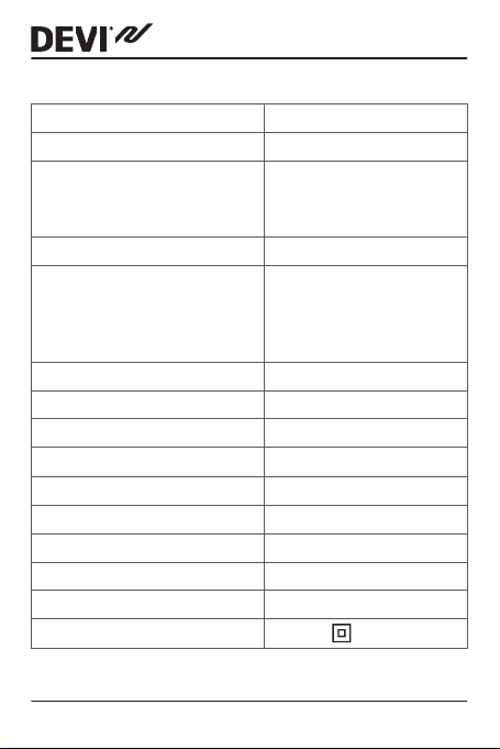
1.1 Technical Specifications
Operation voltage 220-240V~, 50Hz
Standby power consumption Max. 0.93W
Relay:
Resistive load
Inductive load
Sensing units NTC 15kOhm at 25°C
Sensing values:
0°C
25°C
50°C
Hysteresis ± 0.2°C
Ambient temperature -30°C to +50°C
Temperature range -10°C to +50°C
Cable specification max
Ball pressure temperature 75°C
Pollution degree 2 (domestic use)
Type 1C
Storage temperature -20°C to +65°C
IP class 44
Protection class
Max 10A / 2300W @ 230V
cos φ= 0.3 max 1A
42kOhm
15kOhm
6kOhm
1x4mm2 or 2x2,5mm
Class II -
2
4 Installation Guide
Page 5
DEVIreg™ 610
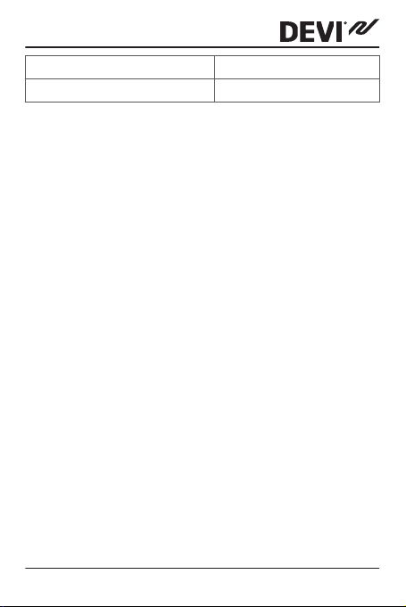
Dimensions 100 x 69.5 x 45mm
Weight 165g
The product complies with the EN/IEC Standard "Automatic
electrical controls for household and similar use":
EN/IEC 60730-1 (general)
▪
EN/IEC 60730-2-9 (thermostat)
▪
1.2 Safety Instructions
Make sure the mains supply to the thermostat is turned off
before installation.
Please also note the following:
The installation of the thermostat must be done by an
▪
authorized and qualified installer according to local
regulations.
The thermostat must be connected to a power supply
▪
via an all-pole disconnection switch.
The sensor is to be considered as live voltage. Have
▪
this in mind if the sensor must be extended.
Always connect the thermostat to continuous power
▪
supply.
Do not expose the thermostat to moisture, water, dust,
▪
and excessive heat.
Installation Guide 5
Page 6

DEVIreg™ 610
2 Mounting Instructions
Please observe the following placement guidelines:
The thermostat can be placed both indoors and out-
▪
doors.
Place the thermostat on a wall, pole, steel/wooden
▪
plate or pipe.
In wet rooms, place the thermostat according
to local regulation on IP classes.
6 Installation Guide
Page 7

-10
10 30
50
C
I
0
-10
10 30
50
C
I
0
DEVIreg™ 610
Follow the steps below to mount the thermostat:
1. Open the thermostat:
Set adjustment button to minimum temperature.
▪
Loosen the 2 screws and open the front cover.
▪
Installation Guide 7
Page 8

DEVIreg™ 610
2. Fasten the thermostat:
Drive the screws through the holes in the bottom
▪
corners of the thermostat.
Seal the holes with the enclosed screw stopper to
▪
maintain the density.
8 Installation Guide
Page 9

IP44
-10T50
D610
L N N NO NC NTC
Mains
220-240V~
L
N
Sensor
Max.Load
10
(1) A
DEVIreg™ 610
3. Connect the thermostat according to the connection
diagram.
Heating: (L-main, N-main, L-load, NO (normally open)
▪
- load).
Cooling: (L-main, N-main, L-load, NC (normally
▪
closed) - load).
The screen of the heating cable must be connected to
the earth conductor of the power supply cable by using a separate connector.
4. Reinstall the front cover.
5. Ensure that the adjustment button can be adjusted
within full temperature range, i.e. from -10°C to +50°C.
Installation Guide 9
Page 10

DEVIreg™ 610
6. Install sensor using the supplied sensor cable - spec.
NTC 15 kΩ @ 25°C.
Press out the blanket located at the bottom of the
▪
thermostat and insert the seal nipple.
Connect sensor to terminals 6+7.
▪
The sensor cable can be extended up to 50 m with 1.5
mm² installation cable without affecting the accuracy
of the thermostat.
Do not place the cable parallel to other installation cables as undesirable signals may be induced.
The installation must be permanent.
If the sensor is to be built in, used for pipe applications, or exposed to pressure, always install it in a conduit.
7. Turn on the power supply.
10 Installation Guide
Page 11

2
Y E A R
DEVIreg™ 610
3 Warranty
4 Disposal Instruction
Installation Guide 11
Page 12

DEVIreg™ 610
12 Installation Guide
Page 13

DEVIreg™ 610
Installation Guide 13
Page 14

DEVIreg™ 610
14 Installation Guide
Page 15

DEVIreg™ 610
Danfoss A/S
Electric Heating Systems
Ulvehavevej 61
7100 Vejle
Denmark
Phone: +45 7488 8500
Fax: +45 7488 8501
E-mail: EH@DEVI.com
www.DEVI.com
Danfoss can accept no responsibility for possible errors in catalogues, brochures and other printed material. Danfoss reserves the right to alter its
products without notice. This also applies to products already on order provided that such alterations can be made without subsequential changes
being necessary in specifications already agreed. All trademarks in this material are property of the respective companies. DEVI and the DEVI logotype are trademarks of Danfoss A/S. All rights reserved.
& VICKK302 Produced by Danfoss © 07/2012
08095435
Page 16

Product Documentation
5 7 0 3 4 6 6 2 0 9 2 5 7
220-240V~
DEVIreg 610 IP44
140F1080
50-60Hz~
DK EL 7224215344
SE EL 8581196
NO EL 5491490
FI SSTL 3531041
-10 to +50°C
10A/2300W@230V~
IP44
Designed in Denmark for Danfoss A/S
 Loading...