

Page 1
Data sheet
DECS 2.0
Danfoss Energy Control System
Description
DECS 2.0
DECS 2.0
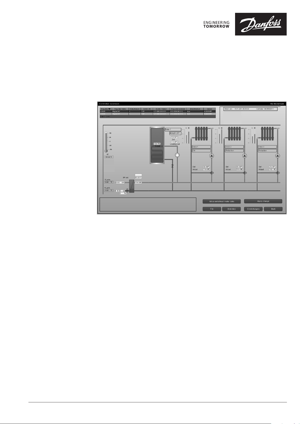
The Danfoss Energy Control System (DECS) is a
web-based SCADA software solution (Supervisory
Control And Data Acquisition) for district heating
systems.
This SCADA solution is typically installed locally
at the heating utility and will automatically
configure its user interface and functionality to
support the application in the controller (for
example Danfoss ECL Comfort 310).
The user of the DECS 2.0 system is able to remote
control and monitor the parameters settings in
the controllers and also monitor actual, reference
and historical values of sensors and meters
connected to the controller.
Danfoss ECL Comfort 310, OPR0010 and OPR0020
controllers are supported by the autoconfiguration features of DECS 2.0, but the ECL
Apex 20 controller can also be supported by
manually adding graphics and programs into
DECS 2.0.
© Danfoss | 2018.05
VD.HX.A5.02 | 1
Page 2
Data sheet DECS 2.0 Danfoss Energy Control System
User benefits The advantages of DECS 2.0 are among others:
Easy installation Easy access
Automatic configuration makes installation easy Access to control and monitor locally and remotely
Advanced techniques are used for simplifying and
automating the installation process. Once the
controller is installed and connected to the
network, the web-based user interface is
generated on the DECS server with just a few
mouse clicks. The DECS server sof tware is installed
at the heating plant and has no special
requirements except for a reliable PC connected
to the internet.
Easy customization Standard
User interface and functionality suits projec t specific
needs
DECS is a visualisation platform based on the
Atvise SCADA system. The user interface and
functionality is easily customized by the system
integrator to project specific requirements using
the Engineering Tool. The scaleability of DECS
ensures an optimized SCADA solution for small,
large and growing district energy networks.
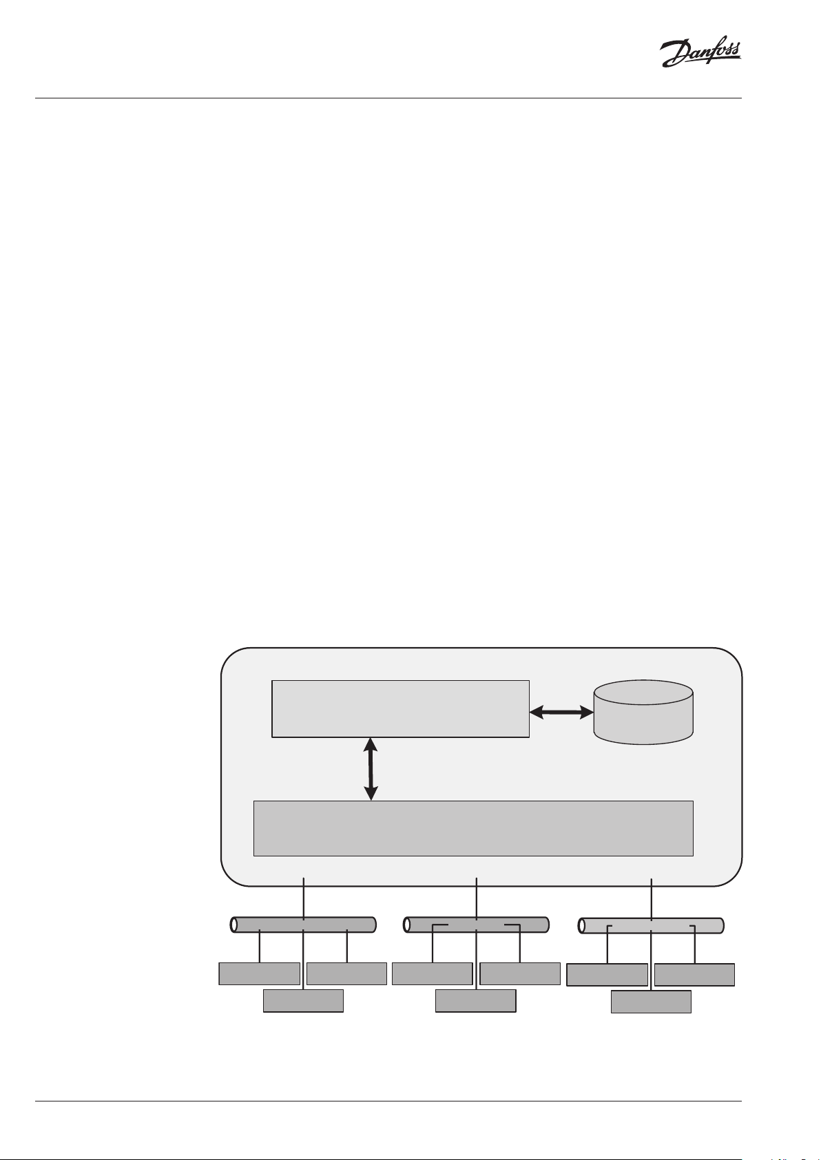
System architecture The architecture of DECS 2.0 is shown below.
The central building blocks of the DECS 2.0 s ystem
are the HMI (Human Machine Inter face) using the
Atvise SCADA Client software from Certec, the
database for storing all logged data from the
controllers and the OPC UA Server software
handling the data communication with the
controllers.
Data is constantly exchanged between the
controllers and the DECS Server. The server
provides an intuitive user interface, which is
accessible from any standard browser on a PC,
laptop or smartphone connected to the internet.
You can control and monitor your heating station
and substation installations from everywhere.
System is built on standardized software and
interfaces
Standardized DECS Server software increases
reliability, lowers hardware complexity and allows
integration of other building automation systems
into the heating system. The communication
interfaces are based on the well-known ModbusRTU or Modbus-TCP protocols, which provide a
reliable, low complexity network.
DECS 2.0 suppor ts data communication between
the server and controllers using Modbus-TCP
(Ethernet), LON bus and Modbus-RS485.
Ethernet (MODBUS-TCP)
Bioma ss
Controller
Bioma ss
Controller
CENTRAL SYSTEM
HMI (atvise)
(Web-Browser / SCADA-System)
OPC UA Server
Bioma ss
Controller
Biomass
Controller
LON network
Biomass
Controller
Bioma ss
Controller
MODBUS (RS485)
Biomass
Controller
Databa se
Bioma ss
Controller
Biomass
Controller
2 | © Danfoss | 2018.05
VD.HX.A5.02
Page 3
Data sheet DECS 2.0 Danfoss Energy Control System
Application DECS 2.0 software automatically adapts its user
interface to fit the application in the controller.
The following controller applications are
supported:
• ECL Comfort 310 controller
* Please see ‘List of app lication keys
supported by DECS 2.0’
Go to http://heating.danfoss.com. In the
‘Documentation’ menu select ‘Electronic
Controllers & PI Controllers > SCADA
Solutions > Data sheet’.
• OPR0020 Controller
* Firmware R4 and newer
• OPR0010 Controller
* Firmware v3.
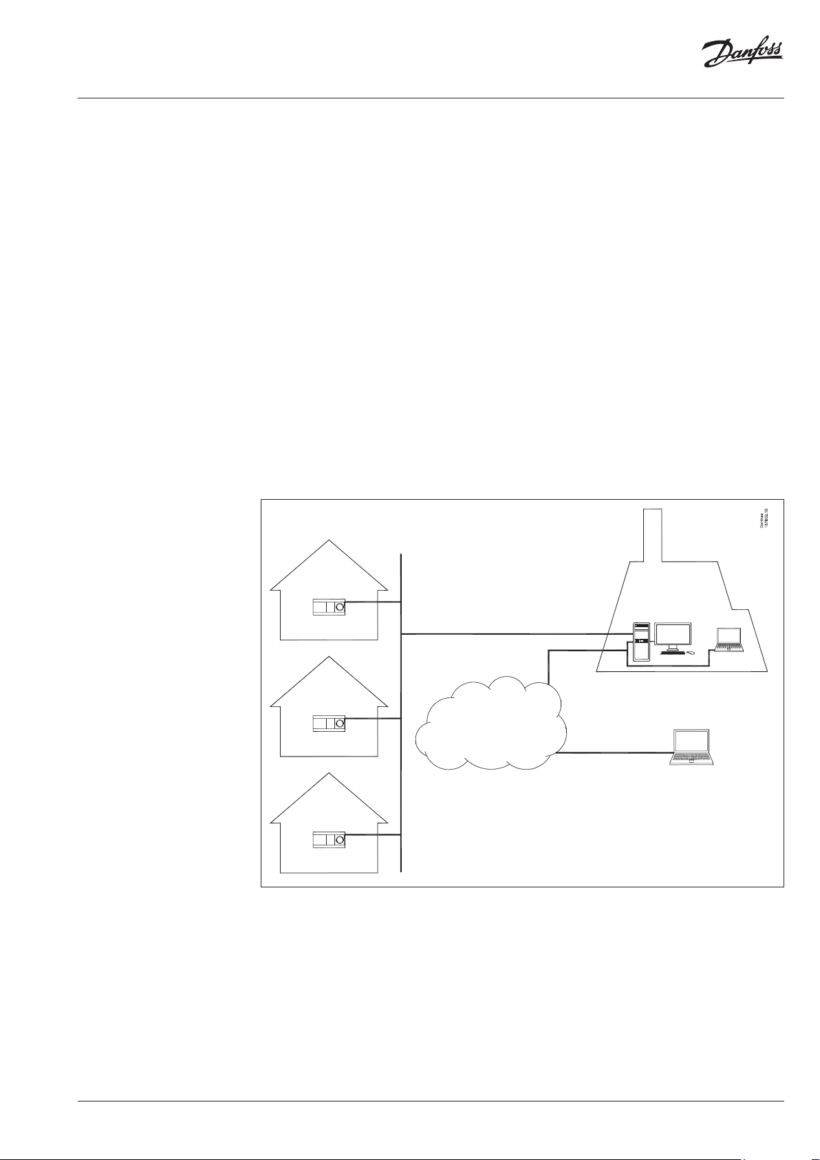
Below is an application example of DECS 2.0 in a
biomass district heating network using
Modbus-RS485 for data communication. The
server, which has DECS 2.0 installed, is located in
the district heating utility and a central laptop is
used for operating the DECS 2.0 system.
j
l
As an option the ECL Apex 20 controller can be
integrated into DECS 2.0 to remote control and
monitor the district heating utility or boiler house.
This requires a system integrator to develop a
customized application for the ECL Apex 20
controller as well as a customized HMI for the
DECS 2.0 system using the OPC server software
for ECL Apex 20.
An external ser vice provider also has access to the
DECS 2.0 system using his laptop connected to
the internet. The server and the ECL Comfort 310
controllers are communicating via an RS485 serial
link using the Modbus protocol.
k
n
p
j
m
j
q
j Private house
k Boiler house for biomass
l Modbus-RS485 network
m Internet
n DECS 2.0 server
o DECS 2.0 client (external service provider)
p DESC 2.0 client (central administration)
q ECL Comfort 310 controller
o
VD.HX.A5.02
© Danfoss | 2018.05 | 3
Page 4
Data sheet DECS 2.0 Danfoss Energy Control System
Application
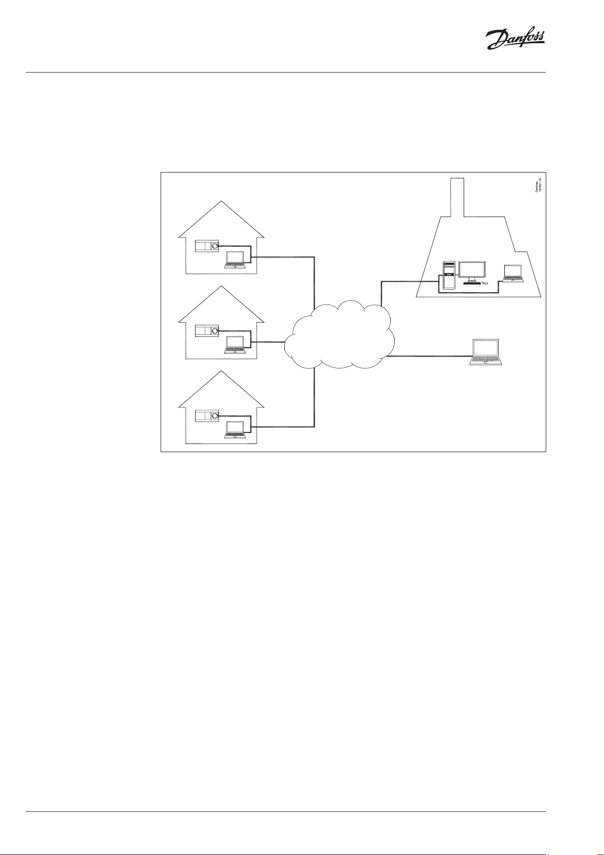
Below is an application example of DECS 2.0 in
biomass district heating network using ModbusTCP (ethernet) for data communication. It is similar
to the previous example except that the ECL
Comfort 310 controllers are communicating with
the server via standard internet connections using
the Modbus protocol.
j
l
j
l
m
j
These internet connections may be used also by
laptops in the houses for browsing the internet
and also to access the DECS 2.0 system.
k
n
p
o
Languages
l
q
j Private house
k Boiler house for biomass
l Modbus-TPC network (internet)
m Internet
n DECS 2.0 server
o DECS 2.0 client (external service provider)
p DESC 2.0 client (central administration)
q ECL Comfort 310 controller
The following languages are supported by the
graphical user interface of DECS 2.0:
• English
• German
• Italian
4 | © Danfoss | 2018.05
VD.HX.A5.02
Page 5

Data sheet DECS 2.0 Danfoss Energy Control System
Data communication
Selection matrix for existing
and new DECS networks
The options for data communication between
controllers and server are listed below. See also
the selection matrix in the next section for
information on selecting the correct data
communication type.
Typ e Description Remarks
Modbus-RS485 Modbus communication via RS485 serial link
is supported by ECL Comfort 310 controllers.
Additional network components may be
needed, i.e. repeaters and gateways.
Modbus-TCP
LON bus
This matrix shows which controllers, data
communication network and SCADA software
are to be used in existing DH networks in case of
warranty or expansion projects.
Modbus communication via ethernet over
internet is supported by OPR0020 and ECL
Comfort 310 controllers.
Additional network components may be
needed, i.e. router and firewall.
LON bus communication via twisted pair serial
link is supported by O PR0020 and ECL Comfort
310 controllers.
The ECL Comfort 310 controller must be
equipped with the ECA34 LON module.
Licenses for components using LON bus are
needed.
For new DH networks the ECL Comfort 310
controller must be used with a Modbus or
Ethernet data network with DECS 2.0.
LON networks should not be
offered in new DECS 2.0 projects.
Modbus is recommended instead.
Existing DH networks New DH networks
Project type Warranty Expansion
Controller
(in substation)
Controller
(in DH utility)
Data network LON (or Ethernet) Modbus-RS485 or Modbus-TCP
Software DECS 1.0
OPR0010 OPR0020 ECL Comfort 310
(incl. LON module)
ECL Apex 20 ECL Apex 20
DECS 2.0 DECS 2.0 OPC Server
(E3)
ECL Comfort 310
(ECL Apex 20)
VD.HX.A5.02
© Danfoss | 2018.05 | 5
Page 6

Data sheet DECS 2.0 Danfoss Energy Control System
Ordering
To use the DECS 2.0 system a server must have
the Atvise SCADA client software and DECS 2.0
software installed. A combined license for Atvise
SCADA Client software and DECS 2.0 software is
If a LON network is used the ECL Comfort 310
controller must be equipped with an ECA34 LON
module and the DECS 2.0 s erver must be equipped
with the Loytec LON NIC.
ordered using the code no. for “DECS 2.0 Software
li cens e”.
In order to use ECL Comfort 310 controllers in a
DECS 2.0 system, each ECL Comfort 310 controller
Additionally a “DECS 2.0 Controller license” must
must have a supported application key installed.
be ordered for each controller registered to the
DECS 2.0 system.
If the DECS 2.0 system is customized to include
also remote control and monitoring of the district
Miscellaneous data communication components
and software drivers may also be needed to
heating utility an ECL Apex 20 controller and ECL
Apex 20 OPC Server software are needed.
establish a DECS 2.0 system. The components
needed depend on the size of the data
communication network and type of network, i.e.
Modbus or LON.
Typ e Designation Code no.
Software DECS 2.0 Software license
DECS 2.0 Controller license
Data
communication
ECA34 LON module for ECL Comfort 310
Loytec LON NIC (PCI/Parallel/USB)
1)
187B1500
187B1501
087H3204
004F9067
Application Please see ‘List of application keys supported by DECS
2.0’
Go to http://heating.danfoss.com. In the
Documentation’ menu select ‘Electronic Controllers &
PI Controllers > SCADA Solutions > Data sheet’.
Controller
3)
ECL Comfort 310 Controller
OPR0020 Controller
ECL Apex 20 Controller
2)
2)
087H3040
00 4F9021
087B2506
Other accessory hardware and soft ware for DECS
2.0 projects are to be purchased locally or
outsourced to local partners/suppliers.
1)
No separate data sheet exists for this product.
To be used only when expanding existing OPR0020/LON
bus based DH networks with ECL310 controllers
2)
See separate data sheet for this component for ordering
details
3)
Max. 1200 controller
6 | © Danfoss | 2018.05
VD.HX.A5.02
Page 7

Data sheet DECS 2.0 Danfoss Energy Control System
Technical data Modbus-RS485 data communication:
Data format • 1 start bit
Communication protocol Modbus RTU
Electrical interface RS485
Cable type Twisted pair + Modbus reference (signal ground)
Max. bus cable length 1200 m (dependent on cable type and
Communication speed • 38.4 Kbit/s half duplex (default)
Network According to the standard Modbus Serial Line
Max. number of Modbus masters 30
Max. number of controllers per Modbus master 247
Modbus-TCP data communication:
Communication protocol Modbus TCP
Electrical interface Ethernet, RJ45 connector
Cable type Standard Ethernet cable (CAT 5)
Max. bus cable length According to Ethernet standard
Communication speed • 10 Mbit/s
TCP Port number 502 (default for Modbus TCP protocol)
Network Star network according to the standard Ethernet
• 8 data bits
• even parity
• 1 stop bit
installation)
• 19.2 Kbit/s half duplex
• 9.6 Kbit/s half duplex
Implementation Guide V1.0
• 100 Mbit/s
implementation guidelines
LON data communication:
Communication protocol LonWorks
Electrical interface RS485
Cable type Twisted pair with shield
Max. bus cable length 500 m (dependent on cable type, termination
and installation)
Communication speed • 78.1 Kbit/s
Network Serial line, star or loop network according to the
LonWorks implementation guidelines by
Echelon
Max. number of controllers per NIC-interface 500
VD.HX.A5.02
© Danfoss | 2018.05 | 7
Page 8

Data sheet DECS 2.0 Danfoss Energy Control System
DECS 2.0 system
requirements
DECS 2.0 server:
Operating system • Microsoft® Windows XP (SP3 with latest
updates installed) (32-bit)
• Microsoft® Windows 7 (SP1 with latest
updates installed) (32-bit)
CPU Intel® or AMD® processor (>= 1,6 GHz)
RAM Minimum: 4 GB RAM
Free disc space 500 GB
(depending on the number of controllers
connected to DECS 2.0 and archieving
frequency)
Video A windows certified graphics card and driver.
Minimum resolution is 1280*1024 pixel
3rd party software • Atvise server V2.1.18 (Certec)
• Loytec network interface software 4.1.x for
LON networks
• Microsoft® .NET Framework 3.5 and
compatible versions
Web browser SVG capable internet browser:
• Mozilla Firefox
• Internet Explorer
• Google Chrome
Web browser must comply with requirements of
Atvise SCADA Client software.
For details about specific browser versions
compatible with Atvise please visit http://www.
atvise.com/en/resources/system-requirements
Backup recommendations RAID Level 1 or RAID Level 5
Data communication interface on DECS 2.0
server:
Modbus-RS485 RS485 port compatible with
• MOXA UPort 1130
• MOXA NPort 5150
• Phoenix Contact FL COM SERVER RS485
Modbus-TCP Ethernet compatible interface
LON bus Loytec LON NIC (LonWorks/EIA 709) using PCI,
Parallel or USB for LON networks
DECS 2.0 client:
Operating system • Microsoft® Windows XP (SP3 with latest
updates installed)
• Microsoft® Windows 7 (SP1 with latest
updates installed)
CPU Intel® or AMD® processor (>= 1,6 GHz)
RAM Minimum: 2 GB RAM
Free disk space 1 GB
Video A windows certified graphics card and driver.
Minimum resolution is 1280*1024 pixel
Web browser SVG capable internet browser:
• Mozilla Firefox
• Internet Explorer
• Google Chrome
Web browser must comply with requirements of
Atvise SCADA Client software.
For details about specific browser versions
compatible with Atvise please visit http://www.
atvise.com/en/resources/system-requirements
8 | © Danfoss | 2018.05
VD.HX.A5.02
Page 9

Data sheet DECS 2.0 Danfoss Energy Control System
Technical literature and
additional information
Typ e Description Literature no.
Operating
guide, DECS
2.0
Operating
guide,
DECS 2.0
User guide,
DECS 2.0
For further information on supported application
keys please visit http://heating.danfoss.com.
In the ‘Documentation’ menu select ‘Electronic
Controllers & PI Controllers > SCADA Solutions.
Operating guide for DECS 2.0 software on
servers incl. Atvise SCADA client, HMI and
database including instructions on how to
configure DECS 2.0
Operating guide on how to use the features
of DECS 2.0 at district heating networks
User guide on how to use the features of DECS
2.0 in homes
VI.HX.C
VI.HX.A
VI.HX.B
VD.HX.A5.02
© Danfoss | 2018.05 | 9
Page 10

Data sheet DECS 2.0 Danfoss Energy Control System
10 | © Danfoss | 2018.05
VD.HX.A5.02
Page 11

Data sheet DECS 2.0 Danfoss Energy Control System
VD.HX.A5.02
© Danfoss | 2018.05 | 11
Page 12

Data sheet DECS 2.0 Danfoss Energy Control System
12 | © Danfoss | DHS-SMT/DK | 2018.05
VD.HX.A5.02
 Loading...