

Page 1

Alarm description
DECS 2.0
1.0 Contents
1.0 Contents ...............................................................................................................................................................................................................................................1
2.0 Alarm menu ......................................................................................................................................................................................................................................... 2
2.1 List of alarms ..................................................................................................................................................................................................................................... 2
2.2 Selecting Priority ............................................................................................................................................................................................................................. 2
2.3 Selecting Status ............................................................................................................................................................................................................................... 2
2.4 Specifying Event Text ..................................................................................................................................................................................................................... 3
2.5 Selecting Source .............................................................................................................................................................................................................................. 3
2.6 Selecting Place ................................................................................................................................................................................................................................. 3
2.7 Selecting Object Number .............................................................................................................................................................................................................3
2.8 Sorting the list of alarms ...............................................................................................................................................................................................................3
2.9 Alarm on sensors ............................................................................................................................................................................................................................. 4
2.10 ECL System Alarms .......................................................................................................................................................................................................................6
2.11 OPR10 System Alarms .................................................................................................................................................................................................................7
2.12 Communication alarms ..............................................................................................................................................................................................................8
2.13 M-bus meter alarms ..................................................................................................................................................................................................................... 8
2.14 ECL Application Alarms ........................................................................................................................................................................................................... 11
© Danfoss |2021.01
AQ173386472022en-010501 | 1
Page 2
Alarm description DECS 2.0
2.0 Alarm menu
2.1 List of alarms
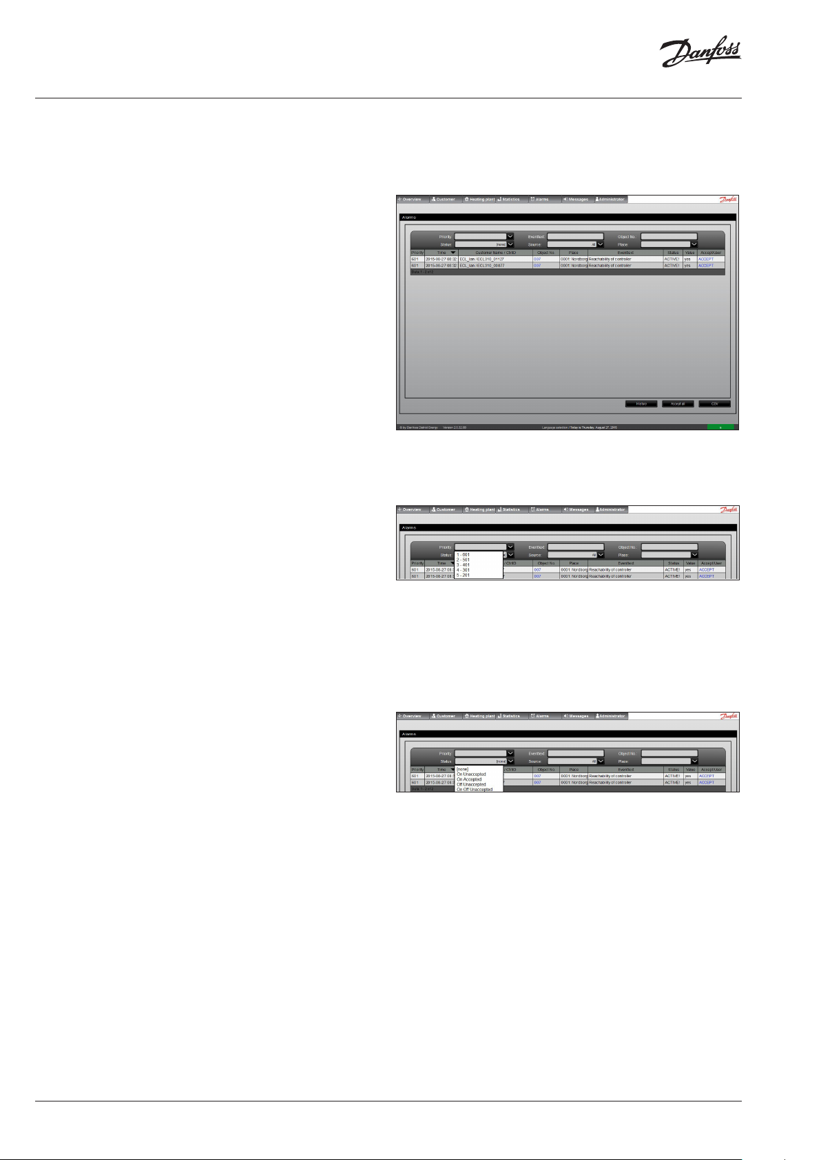
By clicking on the Alarms menu a list of alarms will be shown.
The contents in the list of alarms depend on the selected filtering
criteria. These criteria are Priority, Status, Event text, Source and
Place. Each of these criteria is explained below.
It is possible to see the priority, time stamp, customer name and
controller ID, place, object number, event text, status and accept
status. Each of these information is explained below.
The buttons on the lower right side of the window makes it possible to show History of alarms for a specific period of time or to
quickly Accept All alarms in the list. The list can also be exported to
a CSV file.
2.2 Selecting Priority
Figur 1 shows the Alarms window accessible via the Alarms menu.
The alarms which can be generated by DECS 2.0 each have a predefined priority. In this way the alarms can i.e. be filtered to have
only the highest priority alarms (1 – 601) shown in the list.
By selecting a Priority in the dropdown list then only alarms with
that priority or higher will be shown in the list.
Alarms of highest priority are defined as ‘1 – 601’ and lowest priority as ‘5 – 201’.
The predefined priority of each alarm is shown in the lists of supported alarms.
2.3 Selecting Status
When an alarm is triggered then the status of that alarm will be set
to On. This happens when the trigger condition for that alarm is
fulfilled, i.e. a sensor is disconnected.
If or when the trigger condition for that alarm is no longer fulfilled
then the status of that alarm will be set to Off, i.e. if the sensor is
reconnected.
The trigger conditions are described in the lists of supported
alarms.
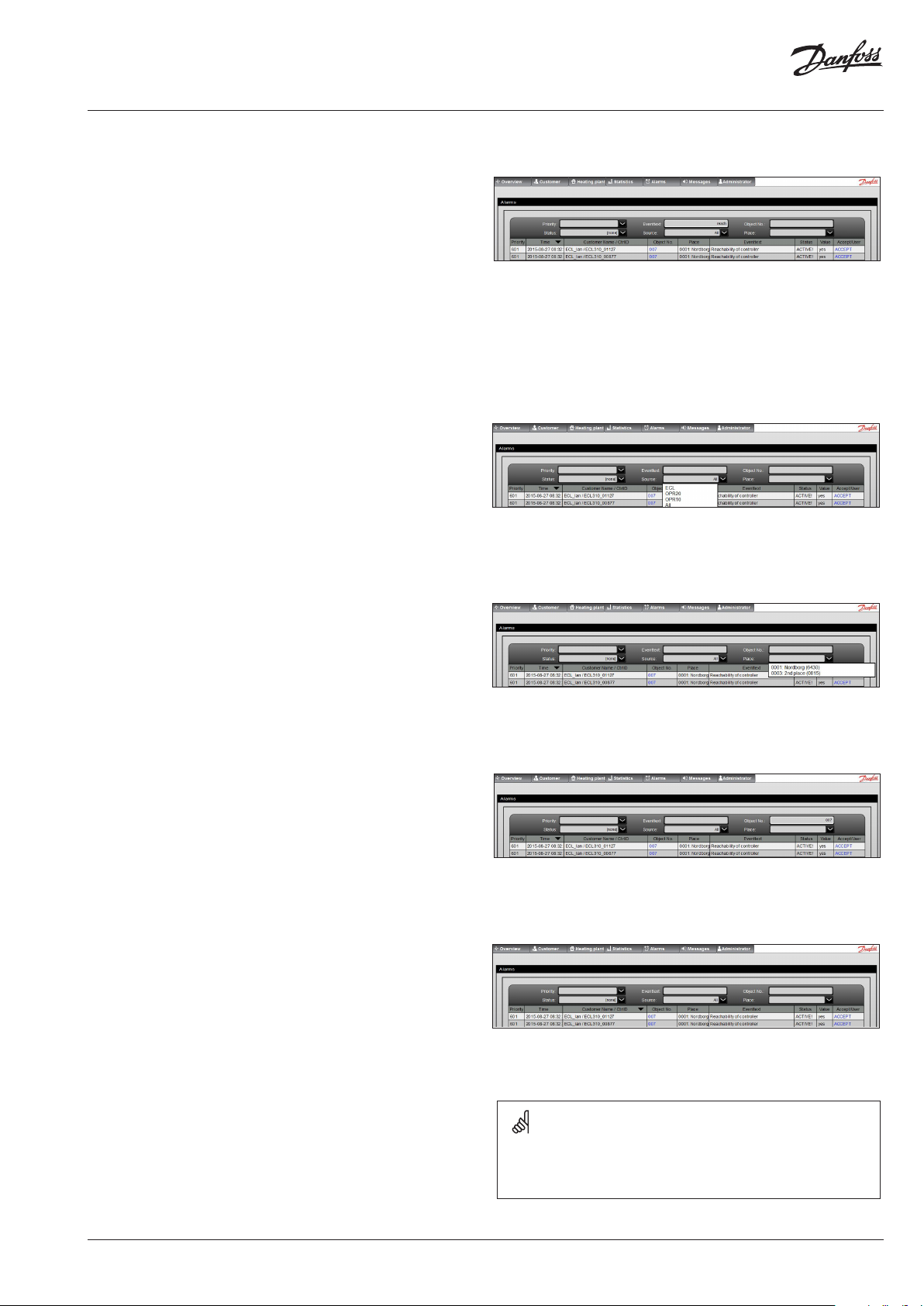
In the Status dropdown list it is possible to select only to show
alarms with a particular Status in the list. If ‘None’ is selected then
no Status filter is applied.
Figur 2 shows how to select Priority in the filter conditions.
Figur 3 shows how to select Status in the filter conditions.
The other options in the dropdown list provide filter criteria which
depends on both the current status of the alarm (On/Off) and
whether or not the alarm has been accepted by a user (Accepted/
Unaccepted). For example, select ‘On Unaccepted’ to show only
the alarms which are currently On and which have not yet been
accepted by a user. Alternatively, select the ‘On Off Unaccepted’
option to show all unaccepted alarms regardless if Status is On or
Off.
2 | © Danfoss| 2021.01
AQ173386472022en-010501
Page 3
Alarm description DECS 2.0
2.4 Specifying Event Text
Each alarm supported by DECS 2.0 has a predefined Event Text
which is shown in the ‘Event Text’ column in the list of alarms.
By specifying a filter criteria to be alarms with a specific Event Text
then only alarms which have this Event Text will be shown in the
list.
It is possible to specify all of the Event Text or just the initial part
of the Event Text, i.e. by specifying “Reachability”, then all alarms
starting with that Event Text will be shown. The filter is not casesensitive.
The predefined Event Text of each alarm is shown in the lists of
supported alarms.
2.5 Selecting Source
DECS 2.0 supports ECL Comfort 296 / 310, OPR20 and OPR10 controllers as source of alarms.
By selecting a source as a filter criteria then only the alarms from
that specific source will be shown in the list of alarms. If ‘All’ is
selected then alarms from any of the sources will be shown in the
list.
The alarms supported by each source are shown in the lists of supported alarms.
Figur 4 shows how to specify an Event Text in the filter conditions.
Figur 5 shows how to select a specific Source in the filter conditions.
2.6 Selecting Place
One or more Places can be created in the General Settings available in the Administrator menu.
Each of these places is selectable in the Place dropdown list. Only
the alarms from that specific Place will be shown in the list of
alarms.
Figur 6 shows how to select a specific Place in the filter conditions.
2.7 Selecting Object Number
You can set a filter for the object number to find only the alarms
from that one.
If you want to see the controller overview of a controller, which
have an active or inactive alarm, then you have to click on the
object number of that controller. This is a hyperlink and the system
will jump to the controller overview display of the controller, on
which the alarm appeared. Figur 7 shows how to select object number.
2.8 Sorting the list of alarms
The list of alarms can be sorted ascending or descending based on
any of the columns shown in the list of alarms.
Click on the title of the column to be used for sorting the list. By
clicking the same column again it will be sorted in reversed order.
The column used for sorting is indicated by an arrow-down (descending) or arrow-up (ascending).
AQ173386472022en-010501
Figur 8 shows how to sort the list of alarms.
Place the mouse pointer on a field in the list of alarms to see
the complete contents of that field.
© Danfoss | 2021.01 | 3
Page 4

Alarm description DECS 2.0
2.9 Alarm on sensors
The ECL controller can be configured to monitor one or more sensor inputs and then trigger an alarm if a sensor is short circuited or
disconnected.
It is described in the installation guide for the application key
installed in the ECL controller how to configure it.
To make the ECL controller monitor an input then it must be activated via the Raw Input Overview menu in the controller.
The ECL controller will then show a magnifying glass next to the
sensor input. Only sensor inputs used by the application itself can
be monitored for alarms.
The sensor input has a measuring range from -60 ... 150 ° C. If the
input is exceeding these limits then the alarm is triggered.
4 | © Danfoss| 2021.01
AQ173386472022en-010501
Page 5

Alarm description DECS 2.0
Event Text Priority
Alarm sensor 1 3 ECL Alarm status goes On if sensor is short circuited or disconnected. The sensor input is monitored by the controller.
Alarm sensor 2 3 ECL Alarm status goes On if sensor is short circuited or disconnected. The sensor input is monitored by the controller.
Alarm sensor 3 3 ECL Alarm status goes On if sensor is short circuited or disconnected. The sensor input is monitored by the controller.
Alarm sensor 4 3 ECL Alarm status goes On if sensor is short circuited or disconnected. The sensor input is monitored by the controller.
Alarm sensor 5 3 ECL Alarm status goes On if sensor is short circuited or disconnected. The sensor input is monitored by the controller.
Alarm sensor 6 3 ECL Alarm status goes On if sensor is short circuited or disconnected. The sensor input is monitored by the controller.
Alarm sensor 7 3 ECL Alarm status goes On if sensor is short circuited or disconnected. The sensor input is monitored by the controller.
Alarm sensor 8 3 ECL Alarm status goes On if sensor is short circuited or disconnected. The sensor input is monitored by the controller.
Alarm sensor 9 3 ECL Alarm status goes On if sensor is short circuited or disconnected. The sensor input is monitored by the controller.
Alarm sensor 10 3 ECL Alarm status goes On if sensor is short circuited or disconnected. The sensor input is monitored by the controller.
Alarm sensor 11 3 ECL Alarm status goes On if sensor is short circuited or disconnected. The sensor input is monitored by the controller.
Alarm sensor 12 3 ECL Alarm status goes On if sensor is short circuited or disconnected. The sensor input is monitored by the controller.
Source
Trigger condition
Alarm ECA 32
sensor 13
Alarm ECA 32
sensor 14
Alarm ECA 32
sensor 15
Alarm ECA 32
sensor 16
Alarm room
unit A Sensor 1
Alarm room
unit B Sensor 1
Sensorerror
Sensor 4 HK2VL
Sensorerror
Sensor 5 HK3VL
Sensorerror
Sensor 6 Boiler
1, HK4VL
4 ECL Alarm status goes On if sensor is short circuited or disconnected. The sensor input is monitored by the controller.
The controller needs to be equipped with an ECA 32 input/output module.
4 ECL Alarm status goes On if sensor is short circuited or disconnected. The sensor input is monitored by the controller.
The controller needs to be equipped with an ECA 32 input/output module.
4 ECL Alarm status goes On if sensor is short circuited or disconnected. The sensor input is monitored by the controller.
The controller needs to be equipped with an ECA 32 input/output module.
4 ECL Alarm status goes On if sensor is short circuited or disconnected. The sensor input is monitored by the controller.
The controller needs to be equipped with an ECA 32 input/output module.
5 ECL Alarm status goes On if sensor is short circuited or disconnected. The sensor input is monitored by the controller.
The controller needs to be connected to an ECA 30 Remote Control Unit.
5 ECL Alarm status goes On if sensor is short circuited or disconnected. The sensor input is monitored by the controller.
The controller needs to be connected to an ECA 30 Remote Control Unit.
3 OPR20 Alarm status goes On if sensor is disconnected. The sensor input is monitored by the controller.
3 OPR20 Alarm status goes On if sensor is disconnected. The sensor input is monitored by the controller.
3 OPR20 Alarm status goes On if sensor is disconnected. The sensor input is monitored by the controller.
Sensorerror
Sensor 7
Boiler 2
3 OPR20 Alarm status goes On if sensor is disconnected. The sensor input is monitored by the controller.
AQ173386472022en-010501
© Danfoss | 2021.01 | 5
Page 6

Alarm description DECS 2.0
2.10 ECL System Alarms
The ECL controller can be configured to monitor one or more
system alarms. It is described in the installation guide for the application key installed in the ECL controller how to configure it, i.e.
the Temperature Monitor.
In case a P330 application key is installed then the Flow Temperature Monitor feature in the ECL controller monitors the flow
temperature of the master circuit (PNU 1040) and circuit 1-4 (PNU
1041-1044). However, only the circuits supported by the sub ap-
plication (P330.1-15) are monitored.
It depends on the application key installed in the ECL controller
which types of system alarms are supported. It can be seen in the
installation guide for the application key and/or in the Alarm Overview menu in the ECL controller.
If the conditions for triggering a system alarm are fulfilled, i.e. a
flow temperature exceeds the limits specified in the ECL control-
ler, the Status of that corresponding alarm is set to On. If/when
the conditions for that alarm are no longer fulfilled then the ECL
DECS 2.0 reads the status of the first 5 types of system alarms in
the ECL controller (PNU 1040-1044).
Event Text Priority Source Trigger condition
Alarm PNU1040 2 ECL Alarm status goes On if the conditions for the alarm specified in the controller are exceeded. When
the conditions are no longer exceeded the Status automatically switches back to Off. The alarm
conditions are monitored by the controller.
Alarm PNU1041 2 ECL Alarm status goes On if the conditions for the alarm specified in the controller are exceeded. When
the conditions are no longer exceeded the Status automatically switches back to Off. The alarm
conditions are monitored by the controller.
Alarm PNU1042 2 ECL Alarm status goes On if the conditions for the alarm specified in the controller are exceeded. When
the conditions are no longer exceeded the Status automatically switches back to Off. The alarm
conditions are monitored by the controller.
controller automatically cancels the alarm, meaning the Status of
the alarm is set back to Off.
Alarm PNU1043 2 ECL Alarm status goes On if the conditions for the alarm specified in the controller are exceeded. When
the conditions are no longer exceeded the Status automatically switches back to Off. The alarm
conditions are monitored by the controller.
Alarm PNU1044 2 ECL Alarm status goes On if the conditions for the alarm specified in the controller are exceeded. When
the conditions are no longer exceeded the Status automatically switches back to Off. The alarm
conditions are monitored by the controller.
6 | © Danfoss| 2021.01
AQ173386472022en-010501
Page 7

Alarm description DECS 2.0
Some examples of system alarms are shown below:
Application key Bit PNU Description
P330 1
A237, A337 1
A247, A260, A347,
A367
A266 1
A377 1
1040
2
3
4
5
2
3
4
5
1
2
3
4
5
2
3
4
5
1041
1042
1043
1044
1040
1041
1042
1043
1044
1040
1041
1042
1043
1044
1040
1041
1042
1043
1044
1040
2
3
4
5
1041
1042
1043
1044
Flow temperature monitor, master circuit
Flow temperature monitor, circuit 1
Flow temperature monitor, circuit 2
Flow temperature monitor, circuit 3
Flow temperature monitor, circuit 4
(Not supported)
Flow temperature monitor, all circuits
(Not supported)
(Not supported)
(Not supported)
(Not supported)
Flow temperature monitor, circuit 1
Flow temperature monitor, circuit 2
(Not supported)
(Not supported)
(Not supported)
Flow temperature monitor, circuit 1
Flow temperature monitor, circuit 2
Flow temperature max monitor, circuit 1
(Not supported)
(Not supported)
Flow temperature monitor, circuit 1
Flow temperature monitor, circuit 2
Flow temperature monitor, circuit 3
(Not supported)
2.11 OPR10 System Alarms
The OPR10 controller can be configured to monitor one or more
system alarms. It is described in the installation guide for the controller how to configure it.
Event Text Priority Source Trigger condition
OPR0010 system
alarm (1)
OPR0010 system
alarm (2)
2 OPR10 Alarm status goes On if the conditions for the alarm specified in the controller are exceeded. When
the conditions are no longer exceeded the Status automatically switches back to Off. The alarm conditions are monitored by the controller.
2 OPR10 Alarm status goes On if the conditions for the alarm specified in the controller are exceeded. When
the conditions are no longer exceeded the Status automatically switches back to Off. The alarm conditions are monitored by the controller.
If the conditions for triggering a system alarm are fulfilled the Status
of that corresponding alarm is set to On. If/when the conditions for
that alarm are no longer fulfilled then the controller automatically
cancels the alarm, meaning the Status of the alarm is set back to Off.
AQ173386472022en-010501
© Danfoss | 2021.01 | 7
Page 8

Alarm description DECS 2.0
2.12 Communication alarms
The communication between DECS 2.0 and the controllers is constantly monitored by DECS 2.0.
If DECS 2.0 cannot reach the controller via the data communication interface, i.e. Modbus-TCP or Modbus-RS485, then it will try
again at next polling cycle. If the controller cannot be reached
after 5 consecutive polling cycles the Reachability status is set to
False and the Communication alarm is triggered.
Event Text Priority Source Trigger condition
Reachability of
controller
Date/time controller
(At least 15 minutes
different from server
time)
1 ECL
OPR10
OPR20
Alarm status goes On if the controller cannot be reached via the data communication interface after
5 consecutive polling cycles. The reachability of the controller is monitored by DECS 2.0.
2 OPR20 Alarm status goes On if the time difference between the controller and DECS 2.0 server time is more
than 15 minutes. The time difference is monitored by DECS 2.0.
2.13 M-bus meter alarms
If an m-bus meter is connected to the controller then DECS 2.0 will
monitor if an error is reported by the meter or if the consumption
value read from the meter is corrupt.
In this situation DECS 2.0 will wait 3 hours until it tries to reach the
controller again. If the controller then is reachable again the Communication alarm is set back to Off.
The interval between each polling cycle depends on the amount of
controllers registered to DECS 2.0 as well as the usage of DECS 2.0,
but is typically 15 minutes.
It also depends on the meter what the conditions are for the error
to be triggered. These details must be found in the documentation
for that specific type of meter.
The meters are monitored at each polling cycle. The interval
between each polling cycle depends on the amount of controllers
registered to DECS 2.0 as well as the usage of DECS 2.0, but is typically 15 minutes.
It depends on the meter which types of error it can report to DECS
2.0 and also in which format the error is reported.
The error from the meter is reported to DECS 2.0 as an integer
value. This value is then shown in the list of alarms. Please consult
the documentation for the meter to learn about the conversion between the error shown in the display of the meter and the integer
value reported to DECS 2.0. See examples of errors supported by
Danfoss energy meters on the next page.
8 | © Danfoss| 2021.01
AQ173386472022en-010501
Page 9

Alarm description DECS 2.0
Event Text Priority Source Trigger condition
ERROR Heatmeter 1 1 ECL, OPR10,
OPR20
ERROR Heatmeter 2 1 ECL, OPR10,
OPR20
ERROR Heatmeter 3 1 ECL, OPR10,
OPR20
ERROR Heatmeter 4 1 ECL, OPR10,
OPR20
ERROR Heatmeter 5 1 ECL, OPR10,
OPR20
ERROR Heatmeter 6 1 OPR10
OPR20
ERROR Heatmeter 7 1 OPR10
OPR20
ERROR Heatmeter 8 1 OPR10
OPR20
ERROR Heatmeter 9 1 OPR10
OPR20
Alarm status goes On if heat meter 1 reports a non-zero error code to DECS 2.0. The m-bus
meter alarm is monitored by DECS 2.0.
Alarm status goes On if heat meter 2 reports a non-zero error code to DECS 2.0. The m-bus
meter alarm is monitored by DECS 2.0.
Alarm status goes On if heat meter 3 reports a non-zero error code to DECS 2.0. The m-bus
meter alarm is monitored by DECS 2.0.
Alarm status goes On if heat meter 4 reports a non-zero error code to DECS 2.0. The m-bus
meter alarm is monitored by DECS 2.0.
Alarm status goes On if heat meter 5 reports a non-zero error code to DECS 2.0. The m-bus
meter alarm is monitored by DECS 2.0.
Alarm status goes On if heat meter 6 reports a non-zero error code to DECS 2.0. The m-bus
meter alarm is monitored by DECS 2.0.
Alarm status goes On if heat meter 7 reports a non-zero error code to DECS 2.0. The m-bus
meter alarm is monitored by DECS 2.0.
Alarm status goes On if heat meter 8 reports a non-zero error code to DECS 2.0. The m-bus
meter alarm is monitored by DECS 2.0.
Alarm status goes On if heat meter 9 reports a non-zero error code to DECS 2.0. The m-bus
meter alarm is monitored by DECS 2.0.
ERROR Heatmeter 10 1 OPR10
OPR20
ERROR Heatquantity 1 2 ECL, OPR10,
OPR20
ERROR Heatquantity 2 2 ECL, OPR10,
OPR20
ERROR Heatquantity 3 2 ECL, OPR10,
OPR20
ERROR Heatquantity 4 2 ECL, OPR10,
OPR20
ERROR Heatquantity 5 2 ECL, OPR10,
OPR20
ERROR Heatquantity 6 2 OPR10
OPR20
ERROR Heatquantity 7 2 OPR10
OPR20
ERROR Heatquantity 8 2 OPR10
OPR20
Alarm status goes On if heat meter 10 reports a non-zero error code to DECS 2.0. The m-bus
meter alarm is monitored by DECS 2.0.
Alarm status goes On if the consumption value read from energy meter 1 is lower than previous readout. The consumption alarm is monitored by DECS 2.0.
Alarm status goes On if the consumption value read from energy meter 2 is lower than previous readout. The consumption alarm is monitored by DECS 2.0.
Alarm status goes On if the consumption value read from energy meter 3 is lower than previous readout. The consumption alarm is monitored by DECS 2.0.
Alarm status goes On if the consumption value read from energy meter 4 is lower than previous readout. The consumption alarm is monitored by DECS 2.0.
Alarm status goes On if the consumption value read from energy meter 5 is lower than previous readout. The consumption alarm is monitored by DECS 2.0.
Alarm status goes On if the consumption value read from energy meter 6 is lower than previous readout. The consumption alarm is monitored by DECS 2.0.
Alarm status goes On if the consumption value read from energy meter 7 is lower than previous readout. The consumption alarm is monitored by DECS 2.0.
Alarm status goes On if the consumption value read from energy meter 8 is lower than previous readout. The consumption alarm is monitored by DECS 2.0.
ERROR Heatquantity 9 2 OPR10
OPR20
ERROR Heatquantity 10 2 OPR10
OPR20
AQ173386472022en-010501
Alarm status goes On if the consumption value read from energy meter 9 is lower than previous readout. The consumption alarm is monitored by DECS 2.0.
Alarm status goes On if the consumption value read from energy meter 10 is lower than
previous readout. The consumption alarm is monitored by DECS 2.0.
© Danfoss | 2021.01 | 9
Page 10

Alarm description DECS 2.0
Error codes supported by Danfoss energy meters are shown in the
table below.
The figures 0-255 are the possible error codes that can be shown
in DECS. 2.0.
The codes in the grey row and the grey column are the possible
error codes that can be shown in the meter display.
C-1 E-8 C-1 +
0 1 2 3 4 5 6 7 8 9 10 11 12 13 14 15
16 17 18 19 20 21 22 23 24 25 26 27 28 29 30 31 E-7
32 33 34 35 36 37 38 39 40 41 42 43 44 45 46 47 E-9
48 49 50 51 52 53 54 55 56 57 58 59 60 61 62 63 E-7 +
64 65 66 67 68 69 70 71 72 73 74 75 76 77 78 79 E-3
80 81 82 83 84 85 86 87 88 89 90 91 92 93 94 95 E-7 +
96 97 98 99 100 101 102 103 104 105 106 107 108 109 110 111 E-9 +
112 113 114 115 116 117 118 119 120 121 122 123 124 125 126 127 E-7 +
128 129 130 131 132 133 134 135 136 137 138 139 140 141 142 143 E-6
144 145 146 147 148 149 150 151 152 153 154 155 156 157 158 159 E-7 +
160 161 162 163 164 165 166 167 168 169 170 171 172 173 174 175 E-9 +
176 177 178 179 180 181 182 183 184 185 186 187 188 189 190 191 E-7 +
192 193 194 195 196 197 198 199 200 201 202 203 204 205 206 207 E-3 +
208 209 210 211 212 213 214 215 216 217 218 219 220 221 222 223 E-7 +
224 225 226 227 228 229 230 231 232 233 234 235 236 237 238 239 E-9 +
240 241 242 243 244 245 246 247 248 249 250 251 252 253 254 255 E-7 +
E-8
E-4 C-1 +
E-4
E-8 +
E-4
C-1 +
E-8 +
E-4
E-1 C-1 +
E-1
E-8 +
E-1
C-1 +
E-8 +
E-1
E-4 +
E-1
C-1 +
E-4 +
E-1
E-8 +
E-4 +
E-1
C-1 +
E-8 +
E-4 +
E-1
E-9
E-3
E-3
E-9 +
E-3
E-6
E-6
E-9 +
E-6
E-6
E-3 +
E-6
E-3 +
E-6
E-9 +
E-3 +
E-6
How to read the table:
Example:
DECS 2.0 shows the error code 146 for a Danfoss heat meter.
Find the figure 146 in the table.
Follow the column vertically to the grey area and you will find E-8.
Hereafter follow the row horizontally to the grey area and you will
find E-7 + E-6.
This means that the error codes E-6, E-7 and E-8 are active in the
heat meter.
You can find an explanation of the possible error codes in the table
on the next page.
10 | © Danfoss| 2021.01
AQ173386472022en-010501
Page 11

Alarm description DECS 2.0
Explanation of error codes
Error code Description
E-1 Temperature measurement error
-) Temperature range outside [-19,9°C ... 199,9°C]
-) sensor short circuit
-) sensor break
E-3 Temperature sensors reversed in hot and cold lines
E-4 Hardware error in ultrasonic measurement
-) transducer or control defective
-) short circuit
E-5 Reading too frequently
E-6 Wrong direction of flow
E-7 No meaningful ultrasonic receive signal
-) air in the measuring path
E-8 No primary voltage (only if mains unit used)
-) supply via backup battery
E-9 Warning: Battery nearly exhausted
C-1 Basic parameter error in flash or RAM
2.14 ECL Application Alarms
DECS 2.0 supports application specific alarms for some application
keys, i.e. A333.
The conditions for such alarms to be triggered are specified in the
Administrator menu.
Event Text Priority Source Trigger condition
Alarm on Sensor 14
- Pump
Flow temperature too
high
Return temperature
too high
2 ECL Alarm status goes On if the specified digital sensor input is High/Active. When the input is Low/Inac-
tive the Status automatically switches back to Off. The alarm conditions are monitored by DECS 2.0.
2 ECL Alarm status goes On if the flow temperature is higher than the specified limit. When the flow tem-
perature is below the limit the Status automatically switches back to Off. The alarm conditions are
monitored by DECS 2.0.
2 ECL Alarm status goes On if the return temperature is higher than the specified limit. When the flow
temperature is below the limit the Status automatically switches back to Off. The alarm conditions are
monitored by DECS 2.0.
DECS 2.0 monitors the corresponding sensor values and detects
if the specified limits are exceeded. If the limit is exceeded then the
Status of that alarm goes On and switches back to Off when the
value is no longer exceeding the limit.
Disposal note
This symbol on the product indicates that it may not be disposed of as household waste.
It must be handed over to the applicable take-back scheme for the recycling of electrical and electronic equipment.
• Dispose of the product through channels provided for this purpose.
• Comply with all local and currently applicable laws and regulations.
AQ173386472022en-010501
© Danfoss | 2021.01 | 11
Page 12

Alarm description DECS 2.0
*087H9249*
AQ173386472022en-01050112 | © Danfoss | DHS-SMDT/DK | 2021.01
 Loading...