

Page 1
Installation Instructions
Decoupling Plate Kit
®
VLT
AutomationDrive FC 360
These instructions provide information about replacement of
the decoupling plate kit in the VLT
Only Danfoss-authorised, qualified personnel is allowed to
repair this equipment. The personnel must be familiar with the
instructions and safety measures described in the
®
AutomationDrive FC 360 Service Manual.
VLT
®
AutomationDrive FC 360.
1.1.1 Items Supplied
Items supplied depend on the ordering number and enclosure
type of the frequency converter.
Ordering numbers Items supplied
132B0258
132B0259
132B0260
132B0284
132B0285
Power decoupling plate, J1
•
I/O decoupling plate
•
Screws (M4x10)
•
Power decoupling plate, J2/J3
•
Screws (M4x10)
•
Power decoupling plate, J4/J5
•
Screws (M4x10)
•
Power decoupling plate, J6
•
Shield plate for line-in and motor
•
Screws (M4x12)
•
Earth plates
•
Power decoupling plate, J7
•
Screws (M4x6)
•
Earth plates
•
1.1.3 Safety Instructions
WARNING
DISCHARGE TIME
The frequency converter contains DC-link capacitors, which
can remain charged even when the frequency converter is
not powered. Failure to wait the specified time after power
has been removed before performing service or repair work,
could result in death or serious injury.
1. Stop the motor.
2. Disconnect AC mains, permanent magnet type
motors, and remote DC-link power supplies,
including battery back-ups, UPS, and DC-link
connections to other frequency converters.
3. Wait for the capacitors to discharge fully, before
performing any service or repair work. The duration
of waiting time is specified in Table 1.2.
Minimum waiting time (minutes)
Voltage [V]
415
380-480 0.37-7.5 kW 11-75 kW
High voltage may be present even when the warning LEDs are off!
Table 1.2 Discharge Time
Table 1.1 Ordering Numbers
1.1.2 Tools Required
Screwdrivers:
•
Flat-edged
-
T10
-
T20
-
T25
-
T30
-
N8 socket wrench
•
N10 socket wrench
•
N5 Allen key
•
Danfoss A/S © Rev. 2014-02-28 All rights reserved. MI06A302
Page 2
Installation Instructions
Decoupling Plate Kit
®
VLT
AutomationDrive FC 360
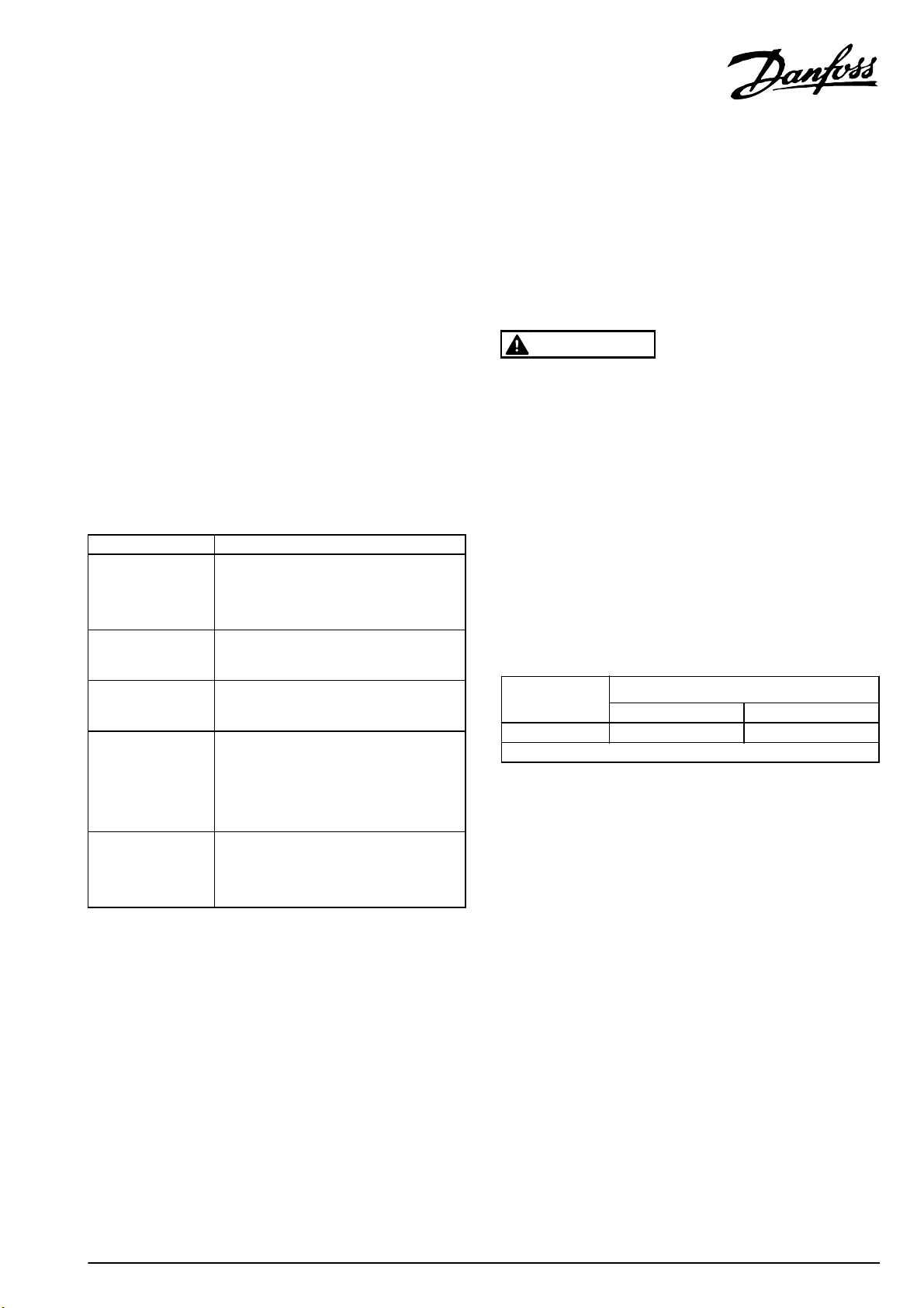
1.1.4 Mounting I/O Decoupling Plate
For J1 Enclosure Type Only
Mount the I/O decoupling bracket on the power decoupling
plate with 2 M4x10 screws (supplied).
Tightening torque: 1.0~1.2 Nm
Illustration 1.1 I/O Decoupling Plate, J1
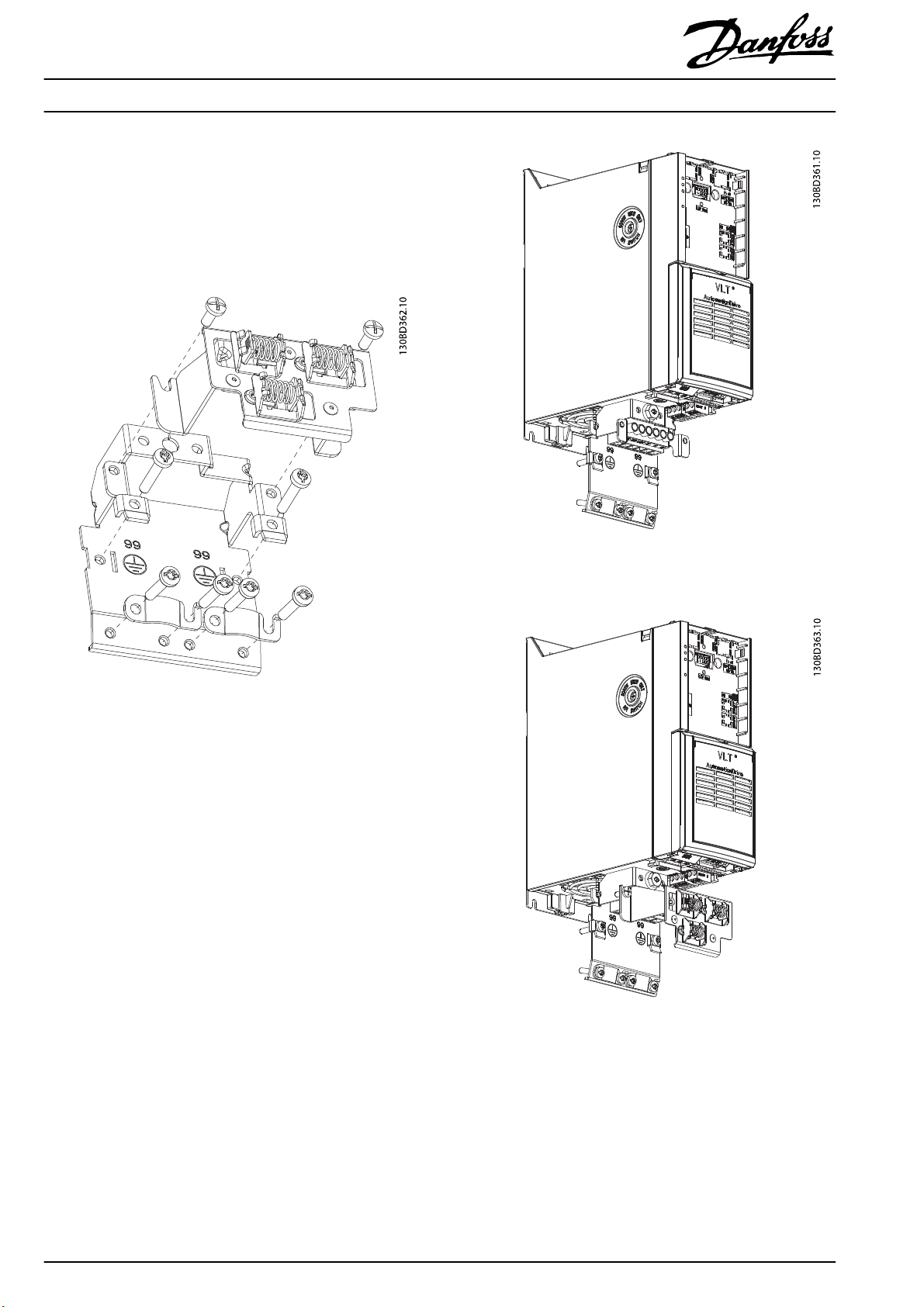
1.1.5 Mounting Power Decoupling Plate
For J1, J2 and J3 Enclosure Types
1. Remove the earth screw (M6x12) from the frequency
converter.
2. Mount the power decoupling plate on the frequency
converter and fasten it with the 2 supplied screws
(M4x10).
Tightening torque: 1.0~1.2 Nm
3. Remount the earth screw (M6x12).
Tightening torque: 0.5~0.8 Nm
Illustration 1.2 Frequency Converter without Decoupling Plate, J1-
J3
Illustration 1.3 Frequency Converter with Decoupling Plate, J1-J3
2
Danfoss A/S © Rev. 2014-02-28 All rights reserved. MI06A302
Page 3

Installation Instructions
Decoupling Plate Kit
®
VLT
AutomationDrive FC 360
For J4 and J5 Enclosure Types
1. Remove the earth plate from the frequency converter
(J4 only).
2. Mount the power decoupling plate on the frequency
converter and fasten it with the 2 supplied screws
(M4x10).
Tightening torque: 1.0~1.2 Nm
3. Remount the earth screw (M6x12).
Tightening torque: 0.5~0.8 Nm
Illustration 1.4 Remove the Earth Plate, J4
Illustration 1.5 Mount the Decoupling Plate, J4-J5
For J6 Enclosure Type
1. Remove the right earth plate.
2. Fit the snaps of the power decoupling plate into the
slots on the frequency converter and fasten the 2
M4x12 screws, as shown in Illustration 1.6.
Illustration 1.6 Mount the Power Decoupling Plate, J6
MI06A302 Danfoss A/S © Rev. 2014-02-28 All rights reserved.
3
Page 4

3. Fasten the shield plate to the power decoupling
plate with 3 screws, and mount the earth plate, as
shown in Illustration 1.7.
Illustration 1.7 Mount the Shield Plate
For J7 Enclosure Type
1. Fit the snaps of the power decoupling plate into the
slots and fasten the 2 M4x6 screws, as shown in
Illustration 1.8.
Illustration 1.8 Mount the Power Decoupling Plate, J7
MI06A302132R0202 Rev. 2014-02-28
*MI06A302*
 Loading...