

Page 1
Item
Enclosure size
Order number
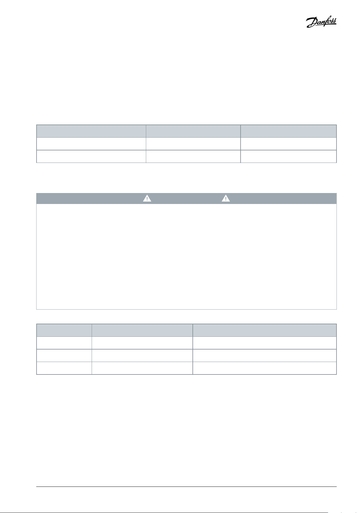
Decoupling plate
H4
120Z0583
Decoupling plate
H5
120Z0583
Voltage [V]
Power range [kW (hp)]
Minimum waiting time (minutes)
3x200
6.0–10 (8.0–15)
15
3x400
6.0–7.5 (8.0–10)
4
3x400
10–30 (15–40)
15
Installation Guide
Decoupling Plate H4–H5
VLT® Compressor Drive CDS 803
1 Introduction
1.1 Order Number for Item Supplied
Table 1: Order Numbers
1.2 Safety Precautions
For important information about safety precautions for installation, refer to the VLT® Compressor Drive CDS 803 Operating Guide.
W A R N I N G
DISCHARGE TIME
The drive contains DC-link capacitors, which can remain charged even when the drive is not powered. High voltage can be
present even when the warning indicator lights are off.
Failure to wait the specified time after power has been removed before performing service or repair work could result in death or
serious injury.
Stop the motor.
-
Disconnect AC mains, permanent magnet type motors, and remote DC-link supplies, including battery back-ups, UPS, and
-
DC-link connections to other drives.
Wait for the capacitors to discharge fully. The minimum waiting time is specified in the table Discharge time and is also visible
-
on the nameplate on the top of the drive.
Before performing any service or repair work, use an appropriate voltage measuring device to make sure that the capacitors
-
are fully discharged.
Table 2: Discharge Time
AN366533284374en-000101 / 130R0595 | 1Danfoss A/S © 2021.03
Page 2
e30bb905.11
e30bb906.11
Decoupling Plate H4–H5
Installation Guide
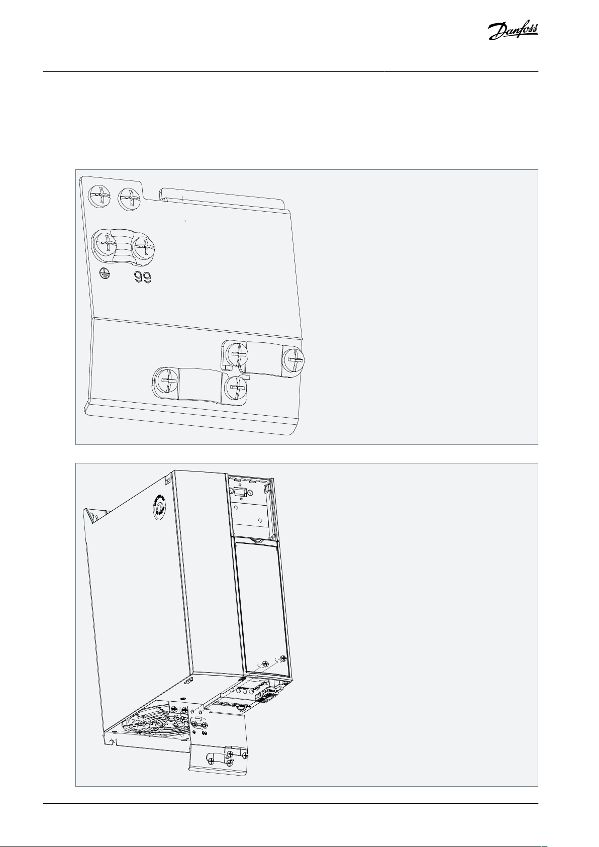
2 Installation
2.1 Mounting the Decoupling Plate
Procedure
1.
Mount the brackets and screws provided on the decoupling plate.
Installation
2.
Mount the decoupling kit on the drive and fasten it with the 2 screws provided. Tightening torque: 2 Nm (17.7 in-lb).
AN366533284374en-000101 / 130R05952 | Danfoss A/S © 2021.03
Page 3

e30bb907.11
Decoupling Plate H4–H5
Installation Guide
The decoupling plate is now mounted on the drive.
Installation
AN366533284374en-000101 / 130R0595 | 3Danfoss A/S © 2021.03
Page 4

Danfoss A/S
Ulsnaes 1
DK-6300 Graasten
vlt-drives.danfoss.com
Danfoss can accept no responsibility for possible errors in catalogs, brochures, and other printed material. Danfoss reserves the right to alter its products without notice.
This also applies to products already on order provided that such alterations can be made without subsequential changes being necessary in specifications already
agreed. All trademarks in this material are property of the respective companies. Danfoss and the Danfoss logotype are trademarks of Danfoss A/S. All rights reserved.
130R0595*
*
AN366533284374en-000101 / 130R0595 Danfoss A/S © 2021.03
*M0030201*
 Loading...