

Page 1
Technical Information
DDC Axial Piston Pumps
Size 20/24
www.danfoss.com
Page 2
Technical Information
DDC Axial Piston Pumps Size 20/24
Revision history Table of revisions
Date Changed Rev
February 2022 Added Option: Detent 0309
December 2021 Minor fix on Design Specifications 0308
November 2021 Added notes at Diagrams and LFV. 0307
October 2021 Added table on CPRV 0306
September 2021 Added to CPRV and Model Code: L. 0305
March 2021 Minor update in Input Shafts AB, BB, DB 0304
January 2021 Minor update in Performance Specifications 0303
November 2020 Minor update in Fluid selection 0302
August 2020 Update CPRV setting 0301
June 2020 Changed document number and version from 'BC00000191' and 'L1104976' to
'BC152886484876'
August 2019 Minor typo 0105
June 2019 Added Size 24 0104
December 2018 Corrected rounding error in performance specifications 0103
February 2017 Change charge pump housing 0102
January 2016 Add SAE-A, 13T Auxiliary Pad Option 0101
April 2015 Minor update in Model Code BB
March 2015 Add Implement Pump and SAE A Mounting Flange Options, and Converted to Danfoss
layout - DITA CMS
March 2013 Paint and Tag AC
November 2011 Minor edits AB
October 2011 First edition AA
0201
BA
2 | © Danfoss | February 2022 BC152886484876en-000309
Page 3

Technical Information
DDC Axial Piston Pumps Size 20/24
Contents
General Description
Design...................................................................................................................................................................................................5
Key Features....................................................................................................................................................................................... 5
Typical Applications........................................................................................................................................................................ 5
System Diagram................................................................................................................................................................................6
Schematic Diagram..........................................................................................................................................................................7
Technical Specifications
Design Specifications......................................................................................................................................................................8
Performance Specifications..........................................................................................................................................................8
Operating Parameters.....................................................................................................................................................................9
Fluid Specifications..........................................................................................................................................................................9
Operation
High Pressure Relief / Check Valve (HPRV)............................................................................................................................10
High pressure relief / check valve with orifice............................................................................................................... 10
Bypass Function..............................................................................................................................................................................11
Charge Pressure Relief Valve (CPRV)....................................................................................................................................... 12
Loop flushing valve.......................................................................................................................................................................13
Control............................................................................................................................................................................................... 14
Direct Displacement Control................................................................................................................................................14
Control Handle Requirements............................................................................................................................................. 14
Operating Parameters
Overview........................................................................................................................................................................................... 15
Input speed...................................................................................................................................................................................... 15
System pressure............................................................................................................................................................................. 15
Charge pressure..............................................................................................................................................................................15
Charge pump inlet pressure...................................................................................................................................................... 16
Case pressure...................................................................................................................................................................................16
Temperature.................................................................................................................................................................................... 16
Viscosity.............................................................................................................................................................................................16
System Design Parameters
Filtration system ............................................................................................................................................................................17
Filtration............................................................................................................................................................................................ 18
Suction filtration....................................................................................................................................................................... 18
Charge pressure filtration......................................................................................................................................................18
External Pressure Filtration................................................................................................................................................... 19
Independent braking system.................................................................................................................................................... 19
Fluid Selection.................................................................................................................................................................................19
Reservoir............................................................................................................................................................................................19
Case Drain.........................................................................................................................................................................................19
Charge Pump...................................................................................................................................................................................20
Charge Pump Sizing/Selection............................................................................................................................................20
Charge Pump Output Flow........................................................................................................................................................ 20
Implement Pump...........................................................................................................................................................................21
Bearing Loads and Life.................................................................................................................................................................23
Applications with External Shaft Loads............................................................................................................................23
Input Shaft...................................................................................................................................................................................23
Shaft Torque.....................................................................................................................................................................................24
Mounting Flange Loads...............................................................................................................................................................25
Estimating Overhung Load Moments...............................................................................................................................25
Understanding and minimizing system noise.....................................................................................................................26
Size Equations................................................................................................................................................................................. 27
Model Code
Model Code: A, B, R, C, E, G, M................................................................................................................................................... 28
Model Code: H, K, F........................................................................................................................................................................29
Model Code: J, S, L......................................................................................................................................................................... 30
Model Code: N, P, Y, Z...................................................................................................................................................................31
©
Danfoss | February 2022 BC152886484876en-000309 | 3
Page 4

Technical Information
DDC Axial Piston Pumps Size 20/24
Contents
Installation Drawings
With Aux-Pad, No Charge Pump, Left Trunnion, SAE A Flange Configuration........................................................32
With Aux-Pad, No Charge Pump, Left Trunnion, SAE B Flange Configuration........................................................ 34
With Charge Pump, No Aux-Pad, Left Trunnion, SAE A Flange Configuration........................................................36
With Charge Pump, No Aux-Pad, Left Trunnion, SAE B Flange Configuration........................................................ 38
With Implement Pump, No Aux-Pad, Left Trunnion, SAE A Flange Configuration................................................40
With Implement Pump, No Aux-Pad, Left Trunnion, SAE B Flange Configuration................................................ 42
Option: Detent................................................................................................................................................................................ 44
Input Shafts: AA, BA, DA.............................................................................................................................................................. 45
Input Shafts: AB, BB, DB............................................................................................................................................................... 46
Input Shafts: AC, BC, DC...............................................................................................................................................................47
Auxiliary Mounting Pads............................................................................................................................................................. 48
Reference Literature
Literature...........................................................................................................................................................................................50
4 | © Danfoss | February 2022 BC152886484876en-000309
Page 5
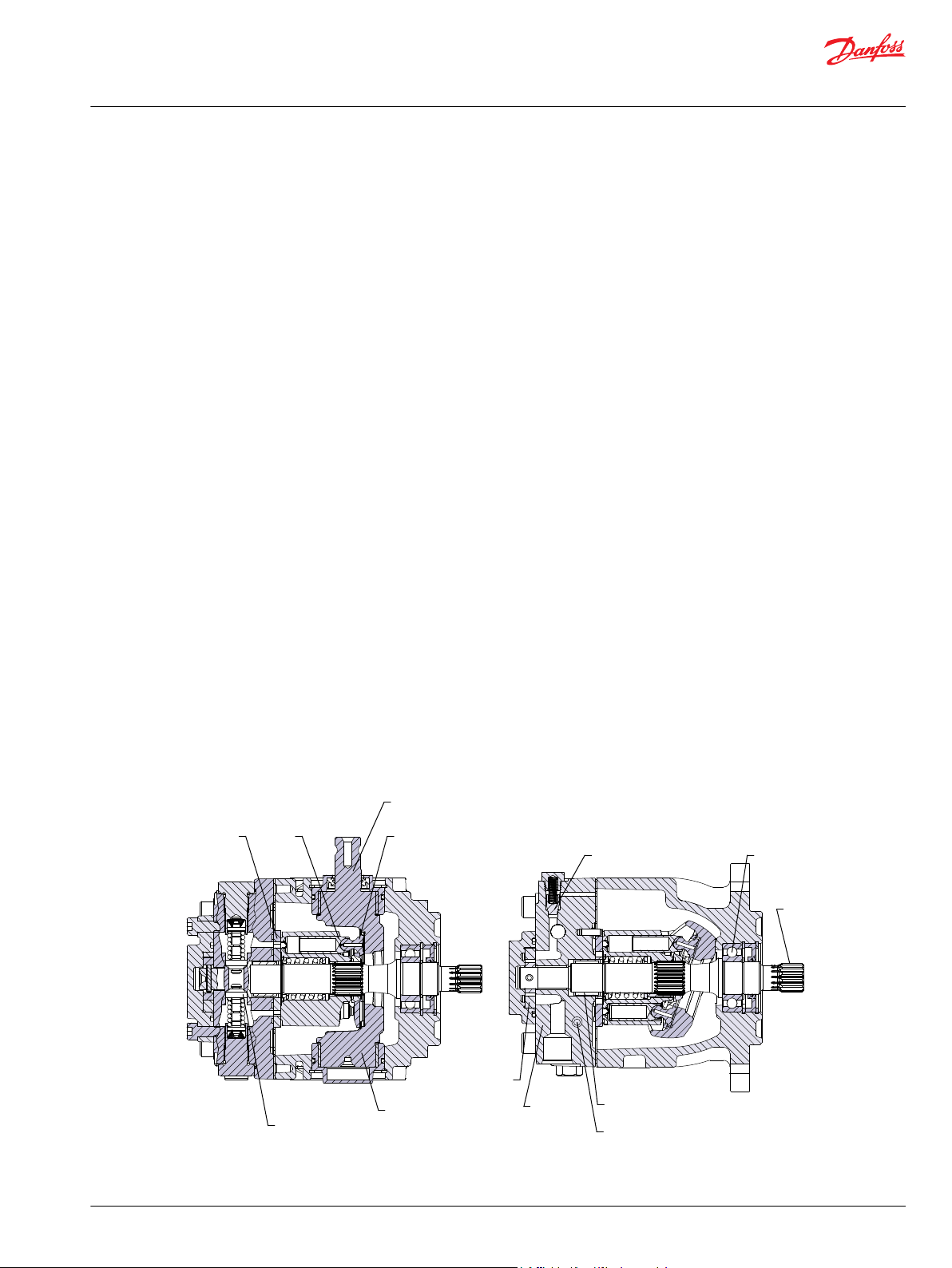
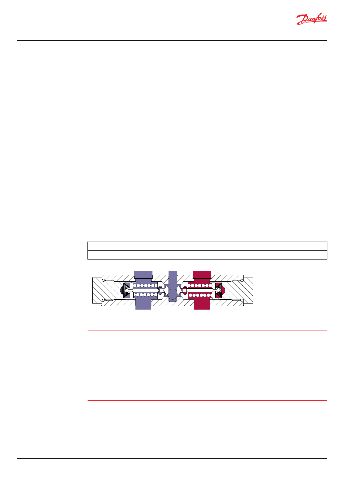
Bypass valve
SlipperValve plate
Trunnion
Charge pump
Needle bearing
Piston
Swashplate
Check and high pressure relief valve
Input
shaft
Ball bearingCharge pressure relief valve
Endcap
P400023
Technical Information
DDC Axial Piston Pumps Size 20/24
General Description
Design
The DDC pump is a compact and lightweight variable displacement axial piston pump intended for use
in closed circuit low to medium power applications. DDC pump is a direct displacement control pump
utilizing an advanced slipper piston design. The flow rate is infinitely variable between zero and
maximum. The direction of flow is commanded by tilting the swashplate in one direction or the other
from the neutral (zero flow) position. Reversing the direction of flow reverses the direction of motor
rotation.
Key Features
Displacement 20/24 cm3/rev [1.22/1.46 in3/rev]
•
Optional bypass valve and loop flushing valve
•
Optional integral charge pump / Implement pump
•
Compact design with best in class pressure ratings and durability
•
Low noise
•
Backed by a global network of Danfoss service provider
•
Mounting flange (SAE-A / B)
•
Typical Applications
DDC Pump Cross-Sectional View
Turf Care
•
Greens Mower
‒
Zero Turn Radius Mower
‒
Loaders
‒
Utility Vehicles
•
Compact Agricultural Machinery
•
Small Compactors
•
Compact Construction Equipment
•
©
Danfoss | February 2022 BC152886484876en-000309 | 5
Page 6
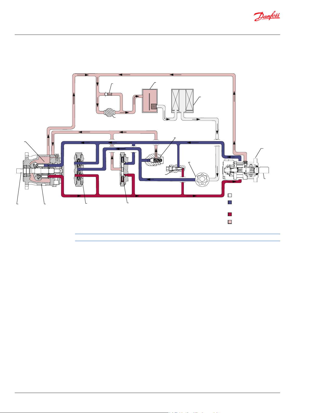
Variable
displacement
pump
Input
shaft
Cylinder
block
assembly
High pressure relief/
check valves
Loop flushing valve
OMR
orbital
motor
Suction flow
Working Loop (High Pressure)
Case flow
Working Loop (Low Pressure) and
Charge Pressure
Output
shaft
Filter
Charge
pump
Reservoir
Heat
exchanger
Heat exchanger
bypass
Charge pressure relief
valve
Bypass
valve
P400024
Technical Information
DDC Axial Piston Pumps Size 20/24
General Description
System Diagram
Loop flushing valve and Charge pump cannot be used together in one pump.
6 | © Danfoss | February 2022 BC152886484876en-000309
Page 7
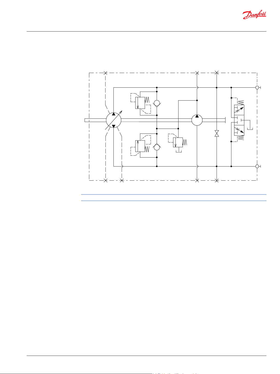
A
B
M3
MA
MB
L1
L3
L2
S
P400025
Technical Information
DDC Axial Piston Pumps Size 20/24
General Description
Schematic Diagram
Loop flushing valve and Charge pump cannot be used together in one pump.
©
Danfoss | February 2022 BC152886484876en-000309 | 7
Page 8
Technical Information
DDC Axial Piston Pumps Size 20/24
Technical Specifications
Design Specifications
Features DDC pump
Design Axial piston pump of journal trunnion design with variable displacement
Direction of input rotation Clockwise or counterclockwise
Pump installation position is discretionary, however the recommended trunnion position
is on the side or at the bottom.
If mounted with trunnion shaft position upward, water and dust tend to collect around
Recommended installation position
Filtration configuration Suction or charge pressure filtration
Other system requirements Independent braking system, suitable reservoir and heat exchanger
Control type Direct displacement control
Performance Specifications
Features Units DDC20 DDC24
Displacement
Mass moment of inertia of rotating components kg•m2 [slug•ft2] 0.0009 [0.0006]
Weight dry
Oil volume Case only liter [US gal] 0.7 [0.1]
Mounting flange
Input shaft outer diameter, Splines, key shafts
Auxiliary mounting flange with metric fasteners, shaft outer
diameter and splines
Suction ports ISO 11926-1, 7/8 -14 (SAE O-ring boss)
Main port configuration ISO 11926-1, 7/8 -14 (SAE O-ring boss) Twin port, radial
Case drain ports L1, L2 , L3 ISO 11926-1, 3/4 -16 (SAE O-ring boss)
Other ports See Installation Drawings on page 32
Customer interface threads Metric fasteners
1
Max Swashplate angle is 18 degrees.
2
See Installation Drawings on page 32 for mounting flange SAE A.
1
With charge pump
With implement pump 11 [24.3]
With auxiliary pad 12 [26.4]
2
the shaft, which may accelerate the deterioration of the shaft seal.
Vertical input shaft installation is acceptable. The housing must always be filled with
hydraulic fluid. Recommended mounting for a multiple pump stack is to arrange the
highest power flow towards the input source.
Consult Danfoss for nonconformance to these guidelines.
cm3/rev [in3/rev] 0-20.0 [0-1.22] 0-24.0 [0-1.46]
10 [22.1]
kg [lb]
ISO3019-1 flange 101-2 (SAE B), 2 bolt
ISO3019-1 flange 82-2 (SAE A), 2 bolt
ISO 3019-1, outer dia 22mm-4 (SAE B, 13 teeth)
ISO 3019-1, outer dia 22mm-1 (Straight Key, Ls)
ISO 3019-1, outer dia 22mm-1 (Straight Key, Special length)
ISO 3019-1, flange 82 - 2, outer dia 16 mm - 4
(SAE A, 9 teeth)
ISO 3019-1, flange 82 - 2, outer dia 19 mm - 4
(SAE A, 11 teeth)
8 | © Danfoss | February 2022 BC152886484876en-000309
Page 9
Technical Information
DDC Axial Piston Pumps Size 20/24
Technical Specifications
Operating Parameters
For definitions of the following specifications, see Operating Parameters on page 15
Features Units DDC pump
Minimum for internal charge
1
supply
Input speed
Minimum for external
charge supply
min-1 (rpm)
Rated 4000
Maximum 4500
Maximum working pressure
System pressure
Maximum pressure 345 [5004]
bar [psi]
Minimum low loop (above
case)
Charge pressure (minimum) bar@15 lpm [psi/USG] 7 [101]
Minimum (continuous)
Charge pump inlet pressure
Minimum (cold start) 0.2 [24]
bar (absolute) [in Hg vacuum]
Maximum 2.0
Case pressure
1
No load condition. Refer to System Design Parameters/Charge Pump on page 20 for details.
Rated
Maximum 3 [43.5]
bar [psi]
500
500
300 [4350]
4 [58]
0.8 [6]
1.5 [21.7]
Fluid Specifications
Features Units DDC pump
intermittent
Viscosity
Minimum 7 [49]
Recommended range 12 - 80 [66 - 370]
Maximum (cold start)
Maximum (cold start)
Temperature range
3
Recommended range 60 - 85
Maximum continuous 104
Maximum intermittent
Cleanliness per ISO 4406 22/18/13
Efficiency (charge pressure
Filtration (recommended
minimum)
filtration)
Efficiency (suction filtration) β35-45=75(β10≥2)
Rercommended inlet screen
mesh size
1
Intermittent=Short term t <1 min per incident and not exceeding 2 % of duty cycle based load-life.
2
Cold start = Short term t < 3 min, p < 50 bar [725 psi], n < 1000 min-1 (rpm)
3
At the hottest point, normally case drain port.
1
5 [42]
mm2/sec. [ SUS]
2
1600 [7500]
-20
°C
115
β-ratio
β15-20=75(β10≥10)
µm 100 - 125
©
Danfoss | February 2022 BC152886484876en-000309 | 9
Page 10
P400026
C
W
Technical Information
DDC Axial Piston Pumps Size 20/24
Operation
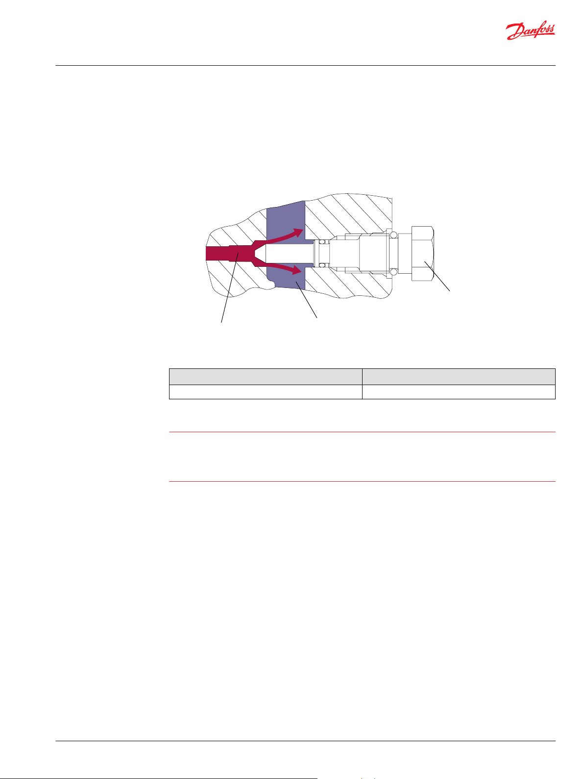
High Pressure Relief / Check Valve (HPRV)
The DDC pump is equipped with a combination high pressure relief and charge check valve. The high
pressure relief valve (HPRV) function is a dissipative (with heat generation) direct acting pressure control
valve for the purpose of limiting excessive system pressures. Each side of the transmission loop has a
non-adjustable HPRV valve. When system pressure exceeds the factory setting of the valve, oil flows into
the charge gallery. The valve is a differential pressure device working with system and charge pressure.
The charge check function acts to replenish the low-side working loop with oil any time the low loop
pressure falls below charge pressure.
Different pressure relief settings may be used at each system port. The order code specifies HPRV
pressure setting availability.
High pressure relief / check valve with orifice
A HPRV valve with an orifice is available as an option. In some applications, it is desirable to use a HPRV/
Check with an orifice to allow for easier neutral adjustment. The orifice connects the working loop to the
charge gallery. It allows a small amount of loop leakage which expands the dead band around the neutral
position of the swashplate. Most applications find it suitable to configure only one side of the system
loop with an orificed HPRV. An orifice referenced to the high pressure side of the loop will decrease
effective efficiency of the system and increase heat into the system. By locating an orifice only on the
reverse drive side of the loop, system efficiency losses are minimized. Increased downhill creep may also
be present.
The HPRV are set at the following flow rates
Check/HPRV without orifice 5 l/min [1.3 US gal/min]
Check/HPRV with orifice 17 l/min [4.5 US gal/min]
Caution
HPRV´s are factory set at a low flow condition. Any application or operating condition which leads to
elevated HPRV flow will cause a pressure rise above the factory setting. Contact your Danfoss
representative for an application review. Using an HPRV with an orifice may increase downhill creep.
Warning
Unintended vehicle or machine movement hazard.
The vehicle must include a braking system redundant to the hydrostatic transmission, sufficient to stop
and hold the vehicle or machine in the event of hydrostatic drive power loss.
10 | © Danfoss | February 2022 BC152886484876en-000309
Page 11
System Loop (Low Pressure)
Bypass Valve
System Loop (High Pressure)
P400027
C
Technical Information
DDC Axial Piston Pumps Size 20/24
Operation
Bypass Function
In some applications it is desirable to bypass the hydraulic fluid around the pump so the machine/load
can be moved without rotating the pump shaft or prime mover. An optional bypass valve mechanically
connects both A & B sides of the system pressure together. The bypass is fully opened when the valve is
turned (opened) counterclockwise 3 revolutions. The valve must be fully closed for normal operation.
Refer to the DDC pump outline drawings for location of the bypass valve.
Bypass valve wrench size and torque
Wrench size Torque N•m [lbf•ft]
17 mm external 12.0 [9.0]
Caution
Excessive speed or extended movement will damage the pump and motor(s)
Avoid excessive speeds and extended load/vehicle movement when using the bypass function. Damage
to the drive motor is possible if the load or vehicle is moved at a speed greater than 20% of maximum or
for a duration exceeding 3 minutes..
©
Danfoss | February 2022 BC152886484876en-000309 | 11
Page 12
Charge Pressure
Case Drain
P400028
C
Technical Information
DDC Axial Piston Pumps Size 20/24
Operation
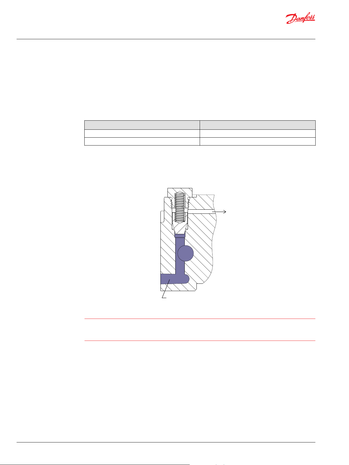
Charge Pressure Relief Valve (CPRV)
An internal charge pressure relief valve (CPRV) regulates charge pressure within the hydraulic circuit. The
CPRV is a direct acting poppet valve that regulates charge pressure at a designated level above case
pressure.
The charge pressure relief valve setting is specified within the model code of the pump. DDC pumps with
charge pump have the CPRV set at 1800 rpm while DDC pumps without charge pump have the CPRV set
with below external charge supply.
Charge pressure setting in MMC [bar] External charge flow [L/min]
7 8.6
11, 14, 18, 21 13.5
The 7 bar charge pressure rise rate, with flow, is approximately 0.8 bar/10 liter [4.4 psi/US gal].
The 11 and 14 bar charge pressure rise rate, with flow, is approximately 1.4 bar /10 liter [7.7 psi/US gal].
The 18 and 21 bar charge pressure rise rate, with flow, is approximately 1.6 bar/10 liter [8.8 psi/US gal] .
Caution
When a DDC pump is used with a variable motor, ensure the available charge pressure matches the
required motor shift pressure. Contact your Danfoss representative for the availability of additional
charge relief settings.
12 | © Danfoss | February 2022 BC152886484876en-000309
Page 13
Working Loop (Low Pressure)
Working Loop (High Pressure)
Case
Notched Diameter
P400029
Oil Temp = 50°C (~30 mm2
/S)
P400301
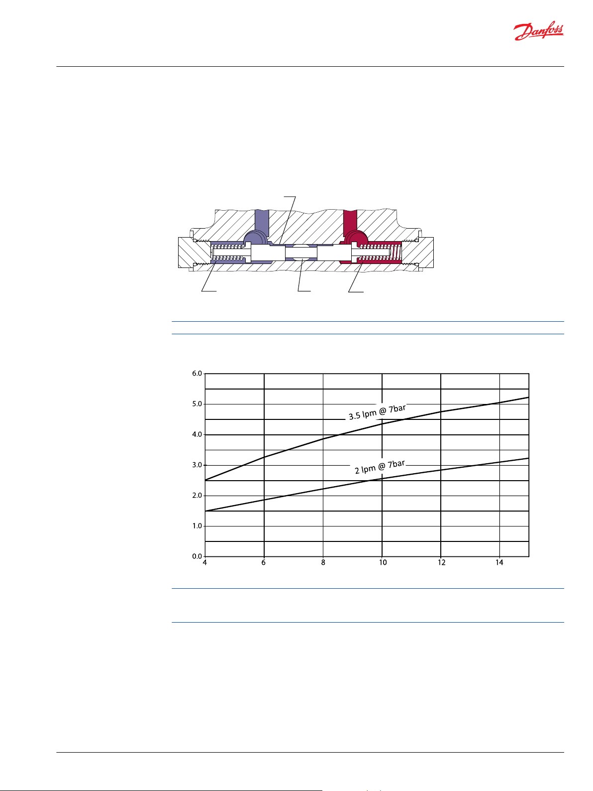
Flow [lpm]
Charge pressure [d bar]
Technical Information
DDC Axial Piston Pumps Size 20/24
Operation
Loop flushing valve
DDC pumps are available with an optional integral loop flushing. A loop flushing valve will remove heat
and contaminants from the main loop at a rate faster than otherwise possible.
The DDC loop flushing design is a simple spring centered shuttle spool with an orifice plug. The shuttle
shifts at approximately 8 bar [115 psi]. The flushing flow is a function of the low loop system pressure
(charge) and the size of the plug.
Loop flushing valve is not available with charge pump combination.
Loop flushing performance
When a DDC pump is used with an external loop flushing shuttle valve, ensure that the charge setting of
the pump matches the setting of the loop flushing shuttle valve. Contact your Danfoss representative for
the availability of additional charge relief settings.
©
Danfoss | February 2022 BC152886484876en-000309 | 13
Page 14
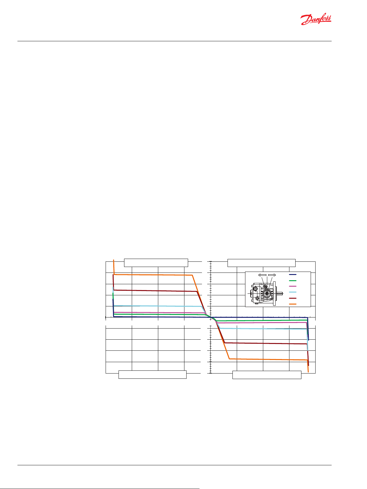
-50
-40
-30
-20
-10
0
10
20
30
40
50
-20 -15 -10 -5 0 5 10 15 20
<pumping mode>
35 bar
6 bar
50 bar
100 bar
200 bar
300 bar
<a>
<b>
Stroke increasing moment
Stroke increasing moment
Stroke decreasing moment
Stroke decreasing moment
Trunnion moment (N•m)
Angle (deg)
P400030
a b
Technical Information
DDC Axial Piston Pumps Size 20/24
Operation
Control
Direct Displacement Control
The DDC pump features direct displacement control (DDC) .The swashplate angle is set directly by a
linkage attached to the swashplate trunnion. Moving the control lever changes the displacement and
direction of flow.
The input shaft is configurable to the left or right side of the pump.
Control Handle Requirements
All DDC pumps will transfer hydraulic forces from within the transmission into the pump control arm
where these forces are seen as a control arm torque. The nature and magnitude of the control arm torque
is a function of transmission operating conditions (pump speed, pressure and displacement) and design
of the DDC valve plate. During normal operation the control arm torque will be stroke reducing, whereas
dynamic braking and downhill operation likely will result in stroke increasing control arm feedback. The
driver and/or the mechanical linkage must be able to return the pump to neutral under all conditions.
Contact Danfoss for additional application support regarding lower control arm torque options.
Maximum allowable control arm torque, applied from the customer linkage, is 79.1 Nm (700 in-lbs).
Linkage stops may be required to limit input torque to the control arm. Maximum swashplate angle is +/18 degrees.
DDC Pumps Control Moment
Input=2000 rpm, Temp=50°C, Shell Tellus 46 Viscosity=30m 2/s
Stroking Speed=1deg/sec, Standard HPRV
14 | © Danfoss | February 2022 BC152886484876en-000309
Page 15

W
Technical Information
DDC Axial Piston Pumps Size 20/24
Operating Parameters
Overview
This section defines the operating parameters and limitations with regard to input speeds and pressures.
Input speed
Minimum speed is the lowest input speed recommended during engine idle condition. Operating below
minimum speed limits pump’s ability to maintain adequate flow for lubrication and power transmission.
Rated speed is the highest input speed recommended at full power condition. Operating at or below
this speed should yield satisfactory product life.
Maximum speed is the highest operating speed permitted. Exceeding maximum speed reduces product
life and can cause loss of hydrostatic power and braking capacity. Never exceed the maximum speed
limit under any operating conditions.
Operating conditions between Rated speed and Maximum speed should be restricted to less than full
power and to limited periods of time. For most drive systems, maximum unit speed occurs during
downhill braking or negative power conditions.
During hydraulic braking and downhill conditions, the prime mover must be capable of providing
sufficient braking torque in order to avoid pump over speed. This is especially important to consider for
turbocharged and Tier 4 engines.
System pressure
Warning
Unintended vehicle or machine movement hazard.
Exceeding maximum speed may cause a loss of hydrostatic drive line power and braking capacity. You
must provide a braking system, redundant to the hydrostatic transmission, sufficient to stop and hold the
vehicle or machine in the event of hydrostatic drive power loss.
System pressure is the differential pressure between system ports A and B. It is the dominant operating
variable affecting hydraulic unit life. High system pressure, which results from high load, reduces
expected life. Hydraulic unit life depends on the speed and normal operating, or weighted average,
pressure that can only be determined from a duty cycle analysis.
Application pressure is the high pressure relief setting normally defined within the order code of the
pump. This is the applied system pressure at which the driveline generates the maximum calculated pull
or torque in the application.
Maximum working pressure is the highest recommended Application pressure. Maximum working
pressure is not intended to be a continuous pressure. Propel systems with Application pressures at, or
below, this pressure should yield satisfactory unit life given proper component sizing.
Maximum pressure is the highest allowable Application pressure under any circumstance. Application
pressures above Maximum Working Pressure will only be considered with duty cycle analysis and factory
approval. Pressure spikes are normal and must be considered when reviewing maximum working
pressure.
All pressure limits are differential pressures referenced to low loop (charge) pressure. Subtract low loop
pressure from gauge readings to compute the differential.
Minimum low loop pressure (above case pressure) is the lowest pressure allowed to maintain a safe
working condition in the low side of the loop.
Charge pressure
An internal charge relief valve regulates charge pressure. Charge pressure maintains a minimum pressure
in the low side of the transmission loop.
The charge pressure setting listed in the order code is the set pressure of the charge relief valve with the
pump in neutral, operating at 1800 min-1 [rpm], and with a fluid viscosity of 32 mm2/s [150 SUS]. Pumps
©
Danfoss | February 2022 BC152886484876en-000309 | 15
Page 16

C
Technical Information
DDC Axial Piston Pumps Size 20/24
Operating Parameters
configured with no charge pump (external charge supply) are set with a charge flow of 18.9 l/min [5.0 US
gal/min] and a fluid viscosity of 32 mm2/s [150 SUS].
The charge pressure setting is referenced to case pressure.
Charge pump inlet pressure
At normal operating temperature charge inlet pressure must not fall below rated charge inlet pressure
(vacuum).
Minimum charge inlet pressure is only allowed at cold start conditions. In some applications it is
recommended to warm up the fluid (e.g. in the tank) before starting the engine and then run the engine
at limited speed until the fluid warms up.
Maximum charge pump inlet pressure may be applied continuously.
Case pressure
Under normal operating conditions, the rated case pressure must not be exceeded. During cold start case
pressure must be kept below maximum intermittent case pressure. Size drain plumbing accordingly.
Caution
Temperature
Viscosity
Possible component damage or leakage
Operation with case pressure in excess of stated limits may damage seals, gaskets, and/or housings,
causing external leakage. Performance may also be affected since charge and system pressure are
additive to case pressure.
The high temperature limits apply at the hottest point in the transmission, which is normally the motor
case drain. The system should generally be run at or below the rated temperature.
The maximum intermittent temperature is based on material properties and should never be
exceeded.
Cold oil will not affect the durability of the transmission components, but it may affect the ability of oil to
flow and transmit power; therefore temperatures should remain 16 °C [30 °F] above the pour point of the
hydraulic fluid.
The minimum temperature relates to the physical properties of component materials. Size heat
exchangers to keep the fluid within these limits. Danfoss recommends testing to verify that these
temperature limits are not exceeded.
Ensure fluid temperature and viscosity limits are concurrently satisfied.
Viscosity For maximum efficiency and bearing life, ensure the fluid viscosity remains in the
recommended range.
The minimum viscosity should be encountered only during brief occasions of maximum ambient
temperature and severe duty cycle operation.
The maximum viscosity should be encountered only at cold start.
16 | © Danfoss | February 2022 BC152886484876en-000309
Page 17

Technical Information
DDC Axial Piston Pumps Size 20/24
System Design Parameters
Filtration system
To prevent premature wear, ensure that only clean fluid enters the hydrostatic transmission circuit. A
filter capable of controlling the fluid cleanliness to ISO 4406, class 22/18/13 (SAE J1165) or better, under
normal operating conditions, is recommended.These cleanliness levels cannot be applied for hydraulic
fluid residing in the component housing/case or any other cavity after transport.
Filtration strategies include suction or pressure filtration. The selection of a filter depends on a number of
factors including the contaminant ingression rate, the generation of contaminants in the system, the
required fluid cleanliness, and the desired maintenance interval. Filters are selected to meet the above
requirements using rating parameters of efficiency and capacity.
Filter efficiency can be measured with a Beta ratio (βX). For simple suction-filtered closed circuit
transmissions and open circuit transmissions with return line filtration, a filter with a β-ratio within the
range of β
and closed circuits with cylinders being supplied from the same reservoir, a higher filter efficiency is
recommended. This also applies to systems with gears or clutches using a common reservoir. For these
systems, a charge pressure or return filtration system with a filter β-ratio in the range of β
10) or better is typically required.
Because each system is unique, only a thorough testing and evaluation program can fully validate the
filtration system. Please see Design Guidelines for Hydraulic Fluid Cleanliness Technical Information,
BC152886482150 for more information.
Cleanliness level and βx-ratio
Filtration
(recommended
minimum)
1
Filter βx-ratio is a measure of filter efficiency defined by ISO 4572. It is defined as the ratio of the number of particles
greater than a given diameter (“x” in microns) upstream of the filter to the number of these particles downstream of
the filter.
35-45
= 75 (β10 ≥ 2) or better has been found to be satisfactory. For some open circuit systems,
= 75 (β10 ≥
15-20
1
Cleanliness per ISO 4406 22/18/13
Efficiency (charge pressure
filtration)
Efficiency (suction and return line
filtration)
Recommended inlet screen mesh
size
β-ratio
µm 100 – 125
β
= 75 (β10 ≥ 10)
15-20
β
= 75 (β10 ≥ 2)
35-45
©
Danfoss | February 2022 BC152886484876en-000309 | 17
Page 18

P400032
Reservoir
Filter
with bypass
Charge
pump
Charge relief valve
To pump case
To Low Pressure
side of loop
Strainer
Potential
workfunction
circuit
P400031
Technical Information
DDC Axial Piston Pumps Size 20/24
System Design Parameters
Filtration
Suction filtration
A suction circuit uses an internal charge pump. The filter is placed between the reservoir and the charge
pump inlet. Do not exceed the inlet vacuum limits during cold start conditions.
Suction filtration
Charge pressure filtration
In a pressure filtration system the pressure filter is remotely mounted in the circuit, downstream of the
charge supply. Pressure filtration is possible with, and without, an internal charge pump. Filters used in
charge pressure filtration circuits should be rated to at least 35 bar [508 psi] pressure. Danfoss
recommends locating a 100 – 125 micron screen in the reservoir or in the charge inlet when using charge
pressure filtration.
A filter bypass valve is necessary to prevent damage to the hydrostatic system. In the event of high
pressure drop associated with a blocked filter or cold start-up conditions, fluid may bypass the filter
temporarily. Avoid working with an open bypass for an extended period. A visual or electrical bypass
indicator is preferred. Proper filter maintenance is mandatory.
Charge pressure filtration
18 | © Danfoss | February 2022 BC152886484876en-000309
Page 19

W
C
Technical Information
DDC Axial Piston Pumps Size 20/24
System Design Parameters
External Pressure Filtration
Charge supply is provided to the DDC pump from an auxiliary work function or dedicated gear pump
circuit. After passing thru a remote filter, the flow enters the pump through the external charge supply
port.
Independent braking system
Warning
Unintended vehicle or machine movement hazard.
The loss of hydrostatic drive line power, in any mode of operation (forward, neutral, or reverse) may cause
the system to lose hydrostatic braking capacity. You must provide a braking system, redundant to the
hydrostatic transmission, sufficient to stop and hold the vehicle or machine in the event of hydrostatic
drive power loss.
Fluid Selection
Ratings and performance data are based on operating with hydraulic fluids containing oxidation, rust
and foam inhibitors. These fluids must possess good thermal and hydrolytic stability to prevent wear,
erosion, and corrosion of pump components.
Reservoir
Case Drain
Caution
Never mix hydraulic fluids of different types.
The hydrostatic system reservoir should accommodate maximum volume changes during all system
operating modes and promote de-aeration of the fluid as it passes through the tank.
A suggested minimum total reservoir volume is 5/8 of the maximum charge pump flow per minute with a
minimum fluid volume equal to 1/2 of the maximum charge pump flow per minute. This allows 30
seconds fluid dwell for removing entrained air at the maximum return flow. This is usually adequate to
allow for a closed reservoir (no breather) in most applications.
Locate the reservoir outlet (charge pump inlet) above the bottom of the reservoir to take advantage of
gravity separation and prevent large foreign particles from entering the charge inlet line. A 100-125 µm
screen over the outlet port is recommended.
Position the reservoir inlet (fluid return) to discharge below the normal fluid level, toward the interior of
the tank. A baffle (or baffles) will further promote de-aeration and reduce surging of the fluid.
The pump housing must remain full of oil at all times. The DDC pump is equipped with three case drain
ports to provide flexibility for hose routing and pump installation. Connect a line from one of the case
drain ports to the reservoir. Case drain fluid is typically the hottest fluid in the system.
©
Danfoss | February 2022 BC152886484876en-000309 | 19
Page 20

Charge pump Flow (lpm)
Speed min-1(rpm)
0
5
10
15
20
25
30
0 500 1000 1500 2000 2500 3000 3500 4000 4500
P400046
7.5 cm
3
4.8 cm
3
3.1 cm
3
Technical Information
DDC Axial Piston Pumps Size 20/24
System Design Parameters
Charge Pump
Charge flow is required on DDC pumps. The charge pump provides flow to make up for system leakage,
maintain a positive pressure in the main circuit, and provide flow for cooling and filtration.
Many factors influence the charge flow requirements and the resulting charge pump size selection. These
factors include system pressure, pump speed, pump swashplate angle, type of fluid, temperature, size of
heat exchanger, length and size of hydraulic lines, auxiliary flow requirements, hydrostatic motor type,
etc. When initially sizing and selecting hydrostatic units for an application, it is frequently not possible to
have all the information necessary to accurately evaluate all aspects of charge pump size selection.
Unusual application conditions may require a more detailed review of charge pump sizing. Charge
pressure must be maintained at a specified level under all operating conditions to prevent damage to the
transmission. Danfoss recommends testing under actual operating conditions to verify this.
Charge Pump Sizing/Selection
In most applications a general guideline is that the charge pump displacement should be at least 10 % of
the total displacement of all components in the system. Unusual application conditions may require a
more detailed review of charge flow requirements. Please refer to Selection of Drive line Components,
BC157786484430 for a detailed procedure.
System features and conditions which may invalidate the 10 % guideline include (but are not limited to):
Continuous operation at low input speeds {< 1500 min-1 (rpm)}
•
High shock loading
•
High input shaft speeds
•
LSHT motors with large displacement
•
Charge Pump Output Flow
Contact your Danfoss representative for application assistance if your application includes any of these
conditions.
Flow at 7 bar [100 psi] charge relief setting, 30mm2/s [140SUS] , 50 °C [122 °F]
20 | © Danfoss | February 2022 BC152886484876en-000309
Page 21

Implement pump Flow (lpm)
Implement Pump Pressure (bar)
0
5
10
15
20
25
0 10 20 30 40 50 60 70
P400136
7.5 cm
3
, 3000 min
-1
5.4 cm
3
, 3000 min
-1
7.5 cm
3
, 1800 min
-1
5.4 cm
3
, 1800 min
-1
Technical Information
DDC Axial Piston Pumps Size 20/24
System Design Parameters
Implement Pump
Implement pump is an integrated charge pump that can be used for the lightly-loaded external work
function. Since implement pump has both external gear pump and charge pump functions, it allows
customers to apply more compact sizing than existing system using external gear pump.
The implement circuit must be of the “open center” type that allows oil from the charge pump circulating
through the control valve to return to the transmission.
In the DDC implement circuit, flow from the charge (implement) pump flows first to the implement
circuit control valve, then to the charge relief and charge check valves. The implement circuit must be
designed to return the implement flow to the transmission. The customer must provide an implement
circuit relief valve in addition to the implement control valve. It is also recommended that the customer
provide a charge pressure filter between the implement control valve and the transmission to prevent
any contaminants created in the implement circuit actuator(s) from entering the charge circuit.
Implement Pump Pressure Specifications
Implement Pump Maximum Pressure
Implement Pump Maximum working pressure (Implement circuit
relief pressure setting)
1
Continuous operation at implement pump relief pressure = Short term t <30sec
85 [1230]
1
bar [psi]
70 [1015]
Flow at 11mm2/s [63SUS], 80°C [176°F]
Low input speed with high pressure and high temperature may cause the flow shortage.
©
Danfoss | February 2022 BC152886484876en-000309 | 21
Page 22

A
B
M3 DE
MA
MB
L1
L3
L2
S
P400052
Technical Information
DDC Axial Piston Pumps Size 20/24
System Design Parameters
Implement Circuit - Schematic Diagram
22 | © Danfoss | February 2022 BC152886484876en-000309
Page 23

Technical Information
DDC Axial Piston Pumps Size 20/24
System Design Parameters
Bearing Loads and Life
Bearing life is a function of speed, system pressure, charge pressure, and swashplate angle, plus any
external side or thrust loads. The influence of swashplate angle includes displacement as well as
direction. External loads are found in applications where the pump is driven with a side/thrust load (belt
or gear) as well as in installations with misalignment and improper concentricity between the pump and
drive coupling. All external side loads will act to reduce the normal bearing life of a pump. Other life
factors include oil type, viscosity and cleanliness.
In vehicle propel drives with no external shaft loads and where the system pressure and swashplate
angle are changing direction and magnitude regularly, the normal B10 bearing life (90 % survival) will
exceed the hydraulic load-life of the unit.
Bearing B10 Life
Bearing Life
(max. swashplate angle)
Applications with External Shaft Loads
DDC pump is designed with bearings that can accept some external radial load. When external loads are
present, the allowable radial shaft loads are a function of the load position relative to the mounting
flange, the load orientation relative to the internal loads, and the operating pressures of the hydraulic
unit. In applications where external shaft loads cannot be avoided, the impact on bearing life can be
minimized by proper orientation of the load. Optimum pump orientation is a consideration of the net
loading on the shaft from the external load, the pump rotating group and the charge pump load.
In applications where the pump is operated such that nearly equal amounts of forward vs. reverse
•
swashplate operation is experienced; bearing life can be optimized by orientating the external side
load at 90° or 270° such that the external side load acts 90° to the rotating group load (for details see
drawing below).
In applications where the pump is operated such that the swashplate is predominantly (> 75 %) on
•
one side of neutral (ie vibratory, conveyor, typical propel); bearing life can be optimized by
orientating the external side load generally opposite of the internal rotating group load. The direction
of internal loading is a function of rotation and which system port has flow out.
DDC pump is designed with bearings that can accept some thrust load such that incidental thrust
•
loads are of no consequence. When thrust loads are anticipated, the allowable load will depend on
many factors and it is recommended that an application review be conducted.
At 140 bar system pressure
7 bar charge pressure
1800 rpm
B10 hours 10000
Contact Danfoss for a bearing life review if external side loads are present.
Thrust loads should be avoided. If thrust loads are anticipated, contact your Danfossrepresentative.
Input Shaft
The maximum allowable radial load (Re) is based on the maximum external moment (Me) and the
distance (L) from the mounting flange to the load.
Re = Me / L
Me Shaft moment
L Flange distance
Re External force to the shaft
Fa Internal rotating group load (changes with direction of flow)
©
Danfoss | February 2022 BC152886484876en-000309 | 23
Page 24

270° Re90° Re
0° Re
180° Re
Input shaft
Me
Shaft bearing
LFa
Re
P400033
1200
1000
800
600
400
200
Re N
0 10 20 30 40 50
distance (L) mm
P400034
Technical Information
DDC Axial Piston Pumps Size 20/24
System Design Parameters
Maximum allowable radial load (Re)
Danfoss recommends clamp-type couplings for applications with radial shaft loads
Contact your Danfoss representative for an evaluation of unit bearing life if you have continuously
applied external loads exceeding 25 % of the maximum allowable radial load (Re) or the pump
swashplate is positioned on one side of center all or most of the time.
Shaft Torque
The rated torque is a measure of tooth wear and is the torque level at which a normal spline life of 2 x
109 shaft revolutions can be expected. The rated torque presumes a regularly maintained minimum level
of lubrication via a moly- disulfide grease in order to reduce the coefficient of friction and to restrict the
presence of oxygen at the spline interface. It is also assumed that the mating spline has a minimum
hardness of Rc 55 and full spline depth.
Maximum torque ratings are based on torsional fatigue strength considering 100.000 full load reversing
cycles. However, a spline running in oil-flooded environment provides superior oxygen restriction in
addition to contaminant flushing. The rated torque of a flooded spline can increase to that of the
maximum published rating. A flooded spline would be indicative of a pump driven by a pump drive or
plugged into an auxiliary pad of a pump.
Maintaining a spline engagement at least equal to the Pitch Diameter will also maximize spline life. Spline
engagements of less than ¾ Pitch Diameter are subject to high contact stress and spline fretting.
Alignment between the mating spline’s pitch diameters is another critical factor in determining the
operating life of a splined drive connection. Plug-in, or rigid spline drive installations can impose severe
radial loads on the shaft. The radial load is a function of the transmitted torque and shaft eccentricity.
24 | © Danfoss | February 2022 BC152886484876en-000309
Page 25

Center of gravity - pump 1
Center of gravity - pump 2
L 1
L 2
Mounting flange
P400035
Technical Information
DDC Axial Piston Pumps Size 20/24
System Design Parameters
Increased spline clearance will not totally alleviate this condition; BUT, increased spline clearance will
prevent mechanical interference due to misalignment or radial eccentricity between the pitch diameters
of the mating splines. Maximize spline life by adding an intermediate coupling between the bearing
supported splined shafts.
Mounting Flange Loads
Estimating Overhung Load Moments
Adding auxiliary pumps and/or subjecting pumps to high shock loads may result in excessive loading of
the mounting flange. Applications which experience extreme resonant vibrations or shock may require
additional pump support. You can estimate the overhung load moment for multiple pump mounting
using the formula below.
MS = GS (W1L1 + W2L2 + ... +WnLn)
MC = GC (W1L1 + W2L2 + ... +WnLn)
Where:
MCRated load moment N•m [lbf•in]
MSShock load moment N•m [lbf•in]
GCRated (vibratory) acceleration (G’s)* m/s2 [ft/s2]
GSMaximum (shock) acceleration (G’s)* m/s2 [ft/s2]
WnWeight of nth pump
LnDistance from mounting flange to CG (center of gravity) of nth pump
(Refer to Installation Drawings on page 32 to locate CG of pump.)
* Carry out calculations by multiplying gravity (g = 9.81 m/s2 [32 ft/s2]) with a given factor. This factor depends
on the application.
Refer to the table below, for allowable overhung load moment values.
Shaft loading parameters
©
Danfoss | February 2022 BC152886484876en-000309 | 25
Page 26

Technical Information
DDC Axial Piston Pumps Size 20/24
System Design Parameters
Mounting flange load
SAE B flange 461 [4080] 865 [7655]
SAE A flange 216 [1912] 404 [3576]
Only SAE B flange is available for the front pump of Tandem pump.
Typical G loads for various applications
Application Rated (vibratory) acceleration (GR) Maximum (shock) acceleration (GS)
Skid steer loader 4 10
Trencher (rubber tires) 3 8
Asphalt paver 2 6
Windrower 2 5
Aerial lift 1.5 4
Turf care vehicle 1.5 4
Vibratory roller 6 10
Rated moment (MR) Shock load moment (MS)
N•m [lbf•in] N•m [lbf•in]
Understanding and minimizing system noise
Noise is transmitted in fluid power systems in two ways: as fluid borne noise, and structure borne noise.
Fluid-borne noise (pressure ripple or pulsation) is created as pumping elements discharge oil into the
pump outlet. It is affected by the compressibility of the oil, and the pump’s ability to transition pumping
elements from high to low pressure. Pulsations travel through the hydraulic lines at the speed of sound
until there is a change (such as an elbow) in the line. Amplitude varies with overall line length and
position.
Structure borne noise is transmitted wherever the pump casing connects to the rest of the system. The
way system components respond to excitation depends on their size, form, material, and mounting.
System lines and pump mounting can amplify pump noise.
Follow these suggestions to help minimize noise in your application:
Use flexible hoses.
•
Limit system line length.
•
If possible, optimize system line position to minimize noise.
•
If you must use steel plumbing, clamp the lines.
•
If you add additional support, use rubber mounts.
•
Test for resonance in the operating range; if possible avoid them.
•
26 | © Danfoss | February 2022 BC152886484876en-000309
Page 27

Input torque M=
Input power P = =
(l/min)
(N•m)
(kW)
(US gal/min)
(lbf•in)
(hp)
Vg • n • η
v
1000
Vg • ∆p
20 • π • η
m
Q • ∆p
600 • η
t
M • n • π
30 000
Vg • n • η
v
231
Vg • ∆p
2 • π • η
m
Q • ∆p
1714 • η
t
M • n • π
198 000
Based on SI units Based on US units
Input torque M=
Input power P = =
Technical Information
DDC Axial Piston Pumps Size 20/24
System Design Parameters
Size Equations
The following equations are helpful when sizing hydraulic transmissions. Generally, the sizing process is
initiated by an evaluation of the machine system to determine the required transmission speed and
torque to perform the necessary work function. Refer to Selection of Drive Line Components,
BC157786484430, for a more complete description of hydrostatic drive line sizing.
Variables:
Vg = Displacement per rev.
pO = Outlet pressure
pi = Inlet pressure
∆p = pHD – pND (system pressure)
n = Speed
ηv = Volumetric efficiency
ηm = Mechanical efficiency
ηt = Overall efficiency (ηv • ηm)
SI units [US units]
cm3/rev [in3/rev]
bar [psi]
bar [psi]
bar [psi]
min-1 (rpm)
©
Danfoss | February 2022 BC152886484876en-000309 | 27
Page 28

Technical Information
DDC Axial Piston Pumps Size 20/24
Model Code
Model Code: A, B, R, C, E, G, M
A - Base Frame Size
Code Description
20 20 cc/rev
24 24 cc/rev
B - Production Version
Code Description
A Product Version "A"
R - Rotation (Viewed from input shaft)
Code Description
R Right hand, CW
L Left hand, CCW
C - Valve Plate
Code Description
RB CW, High neutral seeking
LB CCW, High neutral seeking
E - Control Arm Location and Configuration (Viewing from input shaft, system port up)
Code Description
RSA Right side, 17mm square, 100% displacement
LSA Left side, 17mm square, 100% displacement
G - Neutral Assist Mechanism and Location
Code Description
NN None
AN Detent
M - Bypass Valve (align with module J)
Code Description
A With bypass
28 | © Danfoss | February 2022 BC152886484876en-000309
Page 29

Technical Information
DDC Axial Piston Pumps Size 20/24
Model Code
Model Code: H, K, F
H - Loop Flushing (align with module J)
Code Description
N None (with Charge/Implement Pump)
D Defeated Loop Flushing (w/o Charge/Implement Pump)
2 With 2 lpm Flushing @ 7bar (w/o Charge/Implement Pump)
3 With 3.5 lpm Flushing @ 7bar (w/o Charge/Implement Pump)
K - Charge Pump Displacement (align with modules F and J)
Code Description
N None with Aux-Pad
3 3.1 cc/rev Charge Pump, Suction, w/o Aux-pad
5 4.8 cc/rev Charge Pump, Suction, w/o Aux-pad
B 7.5 cc/rev Charge Pump, Suction, w/o Aux-pad, CW
C 7.5 cc/rev Charge Pump, Suction, w/o Aux-pad, CCW
D 5.4 cc/rev Implement Pump, Remote, w/o Aux-pad, CW
E 5.4 cc/rev Implement Pump, Remote, w/o Aux-pad, CCW
F 7.5 cc/rev Implement Pump, Remote, w/o Aux-pad, CW
G 7.5 cc/rev Implement Pump, Remote, w/o Aux-pad, CCW
F - Pump Input Shaft (align with modules K and J)
Code
AA 0.875 inch dia, Straight Key, 33 mm
AC 13 teeth, 16/32 pitch
BA 0.875 inch dia, Straight Key, 33 mm
BC 13 teeth, 16/32 pitch
DA 0.875 inch dia, Straight Key, 33 mm
DB 0.875 inch dia, Straight Key, 53 mm
DC 13 teeth, 16/32 pitch
Description
Input Shaft Charge Pump, Aux-Pad
with 3.1/4.8 cc Charge Pump, w/o Aux SplineAB 0.875 inch dia, Straight Key, 53 mm
w/o Charge Pump, w/ Aux SplineBB 0.875 inch dia, Straight Key, 53 mm
with 7.5 cc/rev Charge Pump or Implement Pump w/o
Aux Spline
©
Danfoss | February 2022 BC152886484876en-000309 | 29
Page 30

Technical Information
DDC Axial Piston Pumps Size 20/24
Model Code
Model Code: J, S, L
J - Auxiliary Pad Configuration (align with modules M, H, K and F)
Code Description
Aux-Pad Bypass/Loop Flush
AAN9 SAE-A, 9T Yes/Yes
AAN1 SAE-A, 11T Yes/Yes
AAN3 SAE-A, 13T Yes/Yes
ABN9 SAE-A, 9T Yes/Defeated
ABN1 SAE-A, 11T Yes/Defeated
ABN3 SAE-A, 13T Yes/Defeated
ACA0 w/o Aux Pad, for 3.1/4.8 cc/rev Charge Pump Yes/None
BCF0 w/o Aux Pad, for 7.5 cc/rev Charge Pump or Implement Pump Yes/None
S - Input Flange
Code Description
D SAE B flange
H SAE A flange
L - Charge Relief Valves & Setting
Code Description
07 7 bar
11 11 bar
14 14 bar
18 18 bar
21 21 bar
30 | © Danfoss | February 2022 BC152886484876en-000309
Page 31

Technical Information
DDC Axial Piston Pumps Size 20/24
Model Code
Model Code: N, P, Y, Z
N - System Pressure Protection (Port A) & P - System Pressure Protection (Port B)
Code Description
00N Poppet-type Check Valve
14N High Pressure Relief Valve 140 bar
14A High Pressure Relief Valve 140 bar w/ Orifice, (∅ 0.85)
17N High Pressure Relief Valve 175 bar
17A High Pressure Relief Valve 175 bar w/ Orifice, (∅ 0.85)
19N High Pressure Relief Valve 190 bar
19A High Pressure Relief Valve 190 bar w/ Orifice, (∅ 0.85)
21N High Pressure Relief Valve 210 bar
21A High Pressure Relief Valve 210 bar w/ Orifice, (∅ 0.85)
23N High Pressure Relief Valve 230 bar
23A High Pressure Relief Valve 230 bar w/ Orifice, (∅ 0.85)
25N High Pressure Relief Valve 250 bar
25A High Pressure Relief Valve 250 bar w/ Orifice, (∅ 0.85)
28N High Pressure Relief Valve 280 bar
28A High Pressure Relief Valve 280 bar w/ Orifice, (∅ 0.85)
30N High Pressure Relief Valve 300 bar
30A High Pressure Relief Valve 300 bar w/ Orifice, (∅ 0.85)
Y - Special Hardware
Code Description
NNN None
Z - Paint and Tag
Code Description
NNN Black Paint, Danfoss Logo
©
Danfoss | February 2022 BC152886484876en-000309 | 31
Page 32
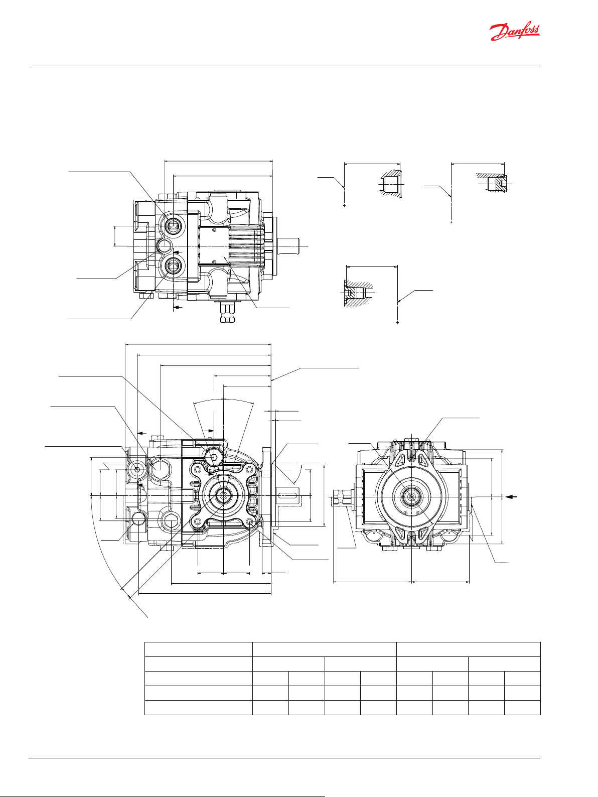
Port ISO 11926-1 -7/8-14
B
B
Paint
Free
53.2 ±0.353.2 ±0.3
65 ±1.5
65 ±1.5
Ø95
2x Ø11.1
±1.5
108
±0.8
79.2
±1.5
+0.3
-0.1
196.5 ±1.2
180.5 ±1.2
149 ±1.2
77 ±0.8
63.94 ±0.8
0.8
±0.5
R0.75 Max
CCW
CW
Case Drain Port “L1”
Port ISO 11926-1 3/4-16
Mounting Flange
Flange 82-2
Per ISO 3019-1 (SAE A)
External Charge Supply Port “E”
From Filter
Or Charge Gage Port “M3”
Port ISO 11926-1 -9/16-18
Bypass
Valve
Paint Free
8x M8x 1.25
13 Full Thread
Depth
4x45°
±3°
45°
±5°
51.5 ±0.8
35 ±0.834 ±0.8
35 ±0.8
31
±0.8
2x35 ±0.8
2x35
±0.8
2x17
+0.06
-0.04
Ø82.55
0
-0.05
18°
Max Disp
18°
Max Disp
6.4
0
-0.5
12±1
134.5 ±1.2
178.5 ±1.2
C
C
2x 35±0.8
±0.82x 35
X
C-C
B-B
System Port “A”
Charge Pressure
Relief Valve
Port ISO 11926-1 -7/8-14
Name Plate
Paint Free
A
A
2x 28
±0.5
153
±1.2
2x 140.5
±1.2
71
±0.8
60.4
2x
±0.8
Shaft
Shaft
Shaft
System Port “B”
P400133
A-A
73.6
2x
±0.8
High Pressure Relief Valve
Paint
Free
Technical Information
DDC Axial Piston Pumps Size 20/24
Installation Drawings
With Aux-Pad, No Charge Pump, Left Trunnion, SAE A Flange Configuration
32 | © Danfoss | February 2022 BC152886484876en-000309
Input shaft rotation CW CCW
Trunnion rotation Right Left Right Left
Trunnion rotation CW CCW CW CCW CW CCW CW CCW
Port A flow Out In In Out In Out Out In
Port B flow In Out Out In Out In In Out
Page 33

X
80.4 ±1.5
74.5 ±1.5
2x 53.2 ±0.2
2x 53.2 ±0.2
4x M10 x1.25
18 Full Thread Depth
180.5±1.2
149±1.2
77±0.8
134.5
Approximate
Center of Gravity
±1.2
35±0.8
35±0.834±0.8
51.5±0.8
Case Drain Port “L2”
Port ISO 11926-1 3/4-16
External Charge Supply Port “E”
From Filter
Or Charge Gage Port “M3”
Port ISO 11926-1 -9/16-18
High Pressure Relief Valve
D
D
System A Gage Port “MA”
Port ISO 11926-1 -9/16-18
Case Drain Port “L3”
Port ISO 11926-1 -3/4-16
E
E
E-E
D-D
2x 30.5±1.2
91
Shaft
Shaft
±0.8
68.5
±0.8
71
±0.8
2x 140.5
±1.2
System B Gage Port “MB”
Port ISO 11926-1 -9/16-18
P400132
(116)
(1)
(1)
Technical Information
DDC Axial Piston Pumps Size 20/24
Installation Drawings
©
Danfoss | February 2022 BC152886484876en-000309 | 33
Page 34

Paint
free
73 ±0.3
87 ±1.5
73 ±0.3
87 ±1.5
2x Ø14.3
+0.3
-0.1
Ø120
±1.5
108
±0.8
79.2
±1.5
193.5
±1.2
177.5±1.2
146±1.2
1.5±0.5
R0.75Max
Mounting Flange
Flange 101-2
Per ISO 3019-1 (SAE B)
74±0.8
60.94±0.8
B
B
C
C
9.7
0
-0.5
45°±5°
Ø101.6
0
-0.05
2x35
±0.8
2x35
±0.8
Paint Free
8x M8x 1.25
13 Full Thread
Depth
15
±1
131.5 ±1.2
2x 35±0.8
±0.82x 35
Bypass
Valve
Paint
Free
2x17
+0.06
-0.04
4x45°
±3°
34 ±0.8 35 ±0.8
51.5 ±0.8
35 ±0.831 ±0.8
CCW
CW
18°
Max Disp
18°
Max Disp
Case Drain Port “
L1
”
Port ISO 11926-1 -3/4-16
Port ISO 11926-1 -9/16-18
High Pressure Relief Valve
External Charge Supply Port “
E
”
From Filter
Or Charge Gage Port “
M3
”
X
C-C
B-B
Port ISO 11926-1-7/8-14
Port ISO 11926-1 -7/8-14
System Port "A"
System Port "B"
Charge Pressure
Relief Valve
Name Plate
Paint Free
A
A
2x 28 ±0.5
2x 137.5
±1.2
60.4
±0.8
150
±1.2
71
Shaft
Shaft
Shaft
±0.8
P400036
2x
A-A
73.6
±0.8
2x
150
±1.2
175.5 ±1.2
Paint
Free
Technical Information
DDC Axial Piston Pumps Size 20/24
Installation Drawings
With Aux-Pad, No Charge Pump, Left Trunnion, SAE B Flange Configuration
34 | © Danfoss | February 2022 BC152886484876en-000309
Page 35

X
177.5
±1.2
131.5
±1.2
Case Drain Port “
L2
”
Port ISO
11926-1 -3/4-16
High Pressure Relief Valve
146
±1.2
74
±0.8
D
D
External Charge Supply Port “E”
From Filter
Or Charge Gage Port “M3”
Port ISO 11926-1 -9/16-18
51.5 ±0.8
35 ±0.8
35 ±0.834 ±0.8
2x 53.2 ±0.2
80.4 ±1.5
74.5 ±1.5
2x 53.2 ±0.2
4x M10 x1.25
18 Full Thread
Depth
Case Drain Port “L3”
PORT ISO 11926-1 -3/4-18
2x 137.5 ±1.2
88 ±0.8
System A Gage Port “MA”
PORT ISO 11926-1 -9/16-18
System B Gage Port “MB”
PORT ISO 11926-1 -9/16-18
2x 30.5±1.2
P400037
E
E
E-E
D-D
68.5
Shaft
Shaft
±0.8
71
±0.8
(111)
(2)
(1)
Approximate
Center of Gravity
Technical Information
DDC Axial Piston Pumps Size 20/24
Installation Drawings
©
Danfoss | February 2022 BC152886484876en-000309 | 35
Page 36

Paint
Free
Paint
Free
53.2 ±0.3
53.2 ±0.3
65 ±1.5
65 ±1.5
Ø95
2x Ø11.1
±1.5
108
±0.8
79.2
±1.5
+0.3
-0.1
186.5±1.2
149±1.2
77 ±0.8
63.94±0.8
0.8
±0.5
R0.75 Max
CCW
CW
Case Drain Port “L1”
Port ISO
11926-1 3/4-16
High Pressure
Relief Valve
Mounting Flange
Flange 82-2
Per ISO 3019-1 (SAE A)
Bypass
Valve
Paint
Free
8x M8x 1.25
13 Full Thread
Depth
51.5 ±0.8
35 ±0.8
34 ±0.8
Ø82.55
0
-0.05
18°
Max Disp
18°
Max Disp
6.4
0
-0.5
12±1
134.5±1.2
B
B
2x35±0.82x35 ±0.8
45°
±5°
2x 35±0.82x 35±0.8
P400135
2x17
+0.06
-0.04
4x45°
±3°
X
A-A
B-B
System Port “A”
Name Plate
Paint Free
Charge Pressure
Relief Valve
A
Port ISO 11926-1 -7/8-14
2x 140.5
±1.2
153
Shaft
Shaft
±1.2
71
±0.8
2x 28 ±0.5
System Port “B”
Port ISO 11926-1 -7/8-14
P400135
73.6
2x
±0.8
Technical Information
DDC Axial Piston Pumps Size 20/24
Installation Drawings
With Charge Pump, No Aux-Pad, Left Trunnion, SAE A Flange Configuration
36 | © Danfoss | February 2022 BC152886484876en-000309
Page 37

E-E
Shaft
D-D
Shaft
Shaft
65.6
±0.8
C-C
71
±0.8
68.5
±0.8
43.2 ±0.8
80.4
±1.5
74.5
±1.5
Charge Gage Port “M3”
Port ISO
R 12.5 Min
11926-1 -7/16-20
149±1.2
77±0.8
51.5 ±0.8
35
±0.8
Case Drain Port “L2”
Port ISO 11926-1 3/4-16
C
C
System A Gage Port “MA”
Port ISO 11926-1 -9/16-18
D
D
E
E
Charge Inlet Port “S”
Port ISO 11926-1 -7/8-14
Case Drain Port “L3”
Port ISO 11926-1 -3/4-16
2x 30.5 ±1.2
91
±0.8
2x 140.5
±1.2
149.5
±1.2
System B Gage Port “MB”
Port ISO 11926-1 -9/16-18
P400134
X
High Pressure
Relief Valve
(105)
(2)
(1)
Approximate
Center of Gravity
Technical Information
DDC Axial Piston Pumps Size 20/24
Installation Drawings
©
Danfoss | February 2022 BC152886484876en-000309 | 37
Page 38

Ø 120
Port ISO 11926-1-7/8-14
Charge Pressure
Relief Valve
Name Plate
Paint Free
Shaft
System Port "B"
P400038
Port ISO 11926-1-7/8-14
System Port "A"
2x 28 ±0.5
2x 137.5
±1.2
150
±1.2
X
B-B
71
±0.8
Shaft
A-A
73.6
2x
±0.8
4x45°
±3°
2x17
+0.06
-0.04
Bypass
Valve
131.5 ±1.2
2x 35 ±0.8
±0.82x 35
15±1
Paint Free
8x M8x 1.25
13 Full Thread
Depth
2x35±0.8
2x35
±0.8
Ø101.6
0
-0.05
1.5±0.5
R0.75 Max
45°±5°
9.7
0
-0.5
CCW
CW
18°
Max Disp
18°
Max Disp
183.5 ±1.2
74 ±0.8
60.94 ±0.8
146 ±1.2
Case Drain Port “L1”
Port ISO 11926-1 3/4-16
Mounting Flange
Flange 101-2
Per ISO 3019-1 (SAE B)
High Pressure
Relief Valve
51.5±0.8
35 ±0.834±0.8
Paint
Free
Paint
Free
108 ±0.8 79.2 ±1.5
±1.5
2x Ø14.3
+0.3
-0.1
87 ±1.5
73 ±0.3 73 ±0.3
87 ±1.5
A
A
B
B
Technical Information
DDC Axial Piston Pumps Size 20/24
Installation Drawings
With Charge Pump, No Aux-Pad, Left Trunnion, SAE B Flange Configuration
38 | © Danfoss | February 2022 BC152886484876en-000309
Page 39

P400039
X
146±1.2
74±0.8
Case Drain Port “L2”
Port ISO 11926-1 3/4-16
High Pressure
Relief Valve
35 ±0.8
74.5
±1.5
43.2 ±0.8
80.4 ±1.5
51.5±0.8
Charge Gage Port “M3”
Port ISO 11926-1 7/16-20
146.5 ±1.2
88 ±0.8
2x 137.5±1.2
System B Gage Port “MB”
Port ISO 11926-1 9/16-18
2x 30.5±1.2
Charge Inlet Port “S”
Port ISO 11926-1 7/8-14
System A Gage Port “MA”
Port ISO 11926-1 9/16-18
Case Drain Port “L3”
Port ISO 11926-1 3/4-16
C
C
E
D
D
Shaft
Shaft
Shaft
C-C
71
±0.8
E-E
68.5
±0.8
D-D
65.6
±0.8
(101)
(2)
(1)
Approximate
Center of Gravity
R 12.5 Min
Technical Information
DDC Axial Piston Pumps Size 20/24
Installation Drawings
©
Danfoss | February 2022 BC152886484876en-000309 | 39
Page 40

Paint
Free
Paint
Free
53.2 ±0.353.2±0.3
65 ±1.5 65 ±1.5
Ø95
2x Ø11.1
±1.5
108
±0.8
79.2
±1.5
+0.3
-0.1
X
P400125
178.5±1.2
149 ±1.2
2x 139 ±1.2
System Port “B”
Port ISO 11926-1 7/8-14
Charge Gage Port “M3” Or
Implement return Port “E”
Charge Pressure
Relief Valve
Port ISO 11926-1 9/16-18
System Port “A”
Port ISO 11926-1 7/8-14
Name Plate
Paint Free
2x 30 ±0.5
B
B
A A
Case Drain Port “L1”
Port ISO
11926-1 3/4-16
Implement Return
Port “E” Or
Charge Gage Port “M3”
Port ISO
11926-1 9/16-18
High Pressure
Relief Valve
Bypass
Valve
51.5 ±0.8
35 ±0.8
32.5±0.832.5 ±0.8
2x17
+0.06
-0.04
4x45°
±3°
12±1
132.5±1.2
2x 35±0.82x 35±0.8
Paint
Free
8x M8x 1.25
13 Full Thread
Depth
R0.75 Max
Ø82.55
0
-0.05
2x35±0.82x35 ±0.8
45°±5°
193.5±1.2
178.5±1.2
145±1.8
77±0.8
63.94±0.8
0.8
±0.5
CCW
CW
18°
Max Disp
18°
Max Disp
6.4
0
-0.5
Mounting Flange
Flange 82-2
Per ISO 3019-1 (SAE A)
C
C
D
D
D-D
Shaft
71
±0.8
Shaft
C-C
60.9
±0.8
B-B
Shaft
73.6
2x
±0.8
Shaft
A-A
59.9
±0.8
Technical Information
DDC Axial Piston Pumps Size 20/24
Installation Drawings
With Implement Pump, No Aux-Pad, Left Trunnion, SAE A Flange Configuration
40 | © Danfoss | February 2022 BC152886484876en-000309
Page 41

Shaft
Shaft
E-E
F-F
71
±0.8
60.9
±0.8
Shaft
Shaft
G-G
68.5
±0.8
H-H
65.6
±0.8
180
±1.2
145 ±1.2
77±0.8
21.5 ±0.8
35
±0.8
51.5 ±0.8
Case Drain Port “L2”
Port ISO 11926-1
3/4-16
Implement
Discharge Port “D”
Port ISO
11926-1 -9/16-18
High Pressure
Relief Valve
E
E
F
F
80.4 ±1.574.5 ±1.5
P400124
145.5 ±1.2
91±0.8
2x 139 ±1.2
System B Gage
Port “MB”
Port ISO 11926-1
9/16-18
2x 30.5±1.2
Charge Inlet
Port “S”
Port ISO 11926-1
7/8-14
System A Gage
Port “MA”
Port ISO 11926-1
9/16-18
Case Drain Port “L3”
Port ISO 11926-1
3/4-16
G
G
H
H
X
(109)
(5)
(1)
Approximate
Center of Gravity
Technical Information
DDC Axial Piston Pumps Size 20/24
Installation Drawings
©
Danfoss | February 2022 BC152886484876en-000309 | 41
Page 42

System Port “A”
Name Plate
Paint Free
Charge Pressure
Relief Valve
Port ISO 11926-1 -7/8-14
System Port “B”
Port ISO 11926-1 -7/8-14
Port ISO 11926-1 -9/16-18
Charge Gage Port “M3” Or
Implement return Port “E”
51.5 ±0.8
35 ±0.8
32.5 ±0.832.5 ±0.8
C
C
D
D
190.5±1.2
175.5±1.2
142±1.8
74±0.8
60.94±0.8
CCW
CW
18°
Max Disp
18°
Max Disp
1.5
±0.5
9.7
0
-0.5
Mounting Flange
Flange 101-2
Per ISO 3019-1 (SAE B)
Paint
Free
8x M8x 1.25
13 Full Thread
Depth
R0.75 Max
Ø101.6
0
-0.05
2x35±0.82x35 ±0.8
45°±5°
15±1
129.5±1.2
2x 35±0.82x 35±0.8
Bypass
Valve
2x17
+0.06
-0.04
4x45°
±3°
Paint
Free
Paint
Free
73 ±0.3
73 ±0.3
87 ±1.5
87 ±1.5
Ø120
2x Ø14.3
±1.5
108
±0.8
79.2
±1.5
+0.3
-0.1
P400127
175.5 ±1.2
146±1.2
2x 136 ±1.2
2x 30±0.5
A
B
B
A
Case Drain Port “L1”
Port ISO 11926-1 3/4-16
High Pressure
Relief Valve
Implement Return Port “E”
Or Charge Gage Port “M3”
Port ISO
11926-1 -9/16-18
B-B
D-D
Shaft
Shaft
Shaft
Shaft
71
±0.8
C-C
A-A
60.9
±0.8
73.6
2x
±0.8
X
Technical Information
DDC Axial Piston Pumps Size 20/24
Installation Drawings
With Implement Pump, No Aux-Pad, Left Trunnion, SAE B Flange Configuration
42 | © Danfoss | February 2022 BC152886484876en-000309
Page 43

80.4 ±1.574.5 ±1.5
P400126
177
±1.2
142 ±1.2
74±0.8
21.5 ±0.8
35
±0.8
51.5 ±0.8
Case Drain Port “L2”
Port ISO 11926-1
3/4-16
High Pressure
Relief Valve
E
F
F
E
X
Implement
Discharge Port “D”
Port ISO
11926-1 -9/16-18
142.5
±1.2
88 ±0.8
2x 136 ±1.2
Case Drain Port “L3”
Port ISO 11926-1
3/4-16
System B Gage
Port “MB”
Port ISO 11926-1
9/16-18
2x 30.5 ±1.2
G
G
H
H
Charge Inlet
Port “S”
Port ISO 11926-1
7/8-14
System A Gage
Port “MA”
Port ISO 11926-1
9/16-18
Shaft
E-E
71
±0.8
Shaft
Shaft
G-G
68.5
±0.8
H-H
65.6
±0.8
Shaft
F-F
60.9
±0.8
(104)
(5)
(1)
Approximate
Center of Gravity
Technical Information
DDC Axial Piston Pumps Size 20/24
Installation Drawings
©
Danfoss | February 2022 BC152886484876en-000309 | 43
Page 44
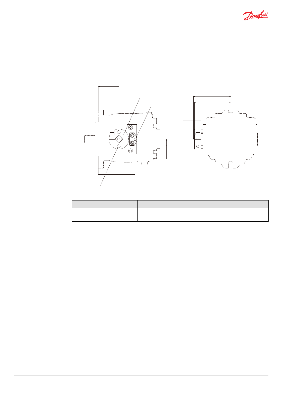
Lever mounting surface
Paint free
Grease nipple
Paint free
±0.8
20 ±0.2
108 ±1.5
111 ±1.5
“GA”
±1.5
2x 21±0.5
“GB”
2x M10 x 1.5 THRU
P400749
Technical Information
DDC Axial Piston Pumps Size 20/24
Installation Drawings
Option: Detent
Mounting flange "GA" dimension "GB" dimension
SAE A 63.94 112.44
SAE B 60.94 109.44
44 | © Danfoss | February 2022 BC152886484876en-000309
Page 45

A-A
45°
2x Full R
A
A
Mating Coupling
Must Not Protrude
Beyond This Point
Mounting Flange
Flange 82-2
Per ISO 3019-1 (SAE A)
3
±0.3
+0.4
0
1.5
±0.4
±0.1
33
±0.3
5
±1
±0.3°
25.4
18.58
Ø22.2
+0.03
0
6.35
+0.05
0
Ø52
+0.03
0
P400128
Paint Free
33
±0.3
8±1
Paint Free
Mating Coupling
Must Not Protrude
Beyond This Point
Mounting Flange
Flange 101-2
Per ISO 3019-1 (SAE B)
2x FULL R
B
B
25.4
+0.4
0
3 ±0.3
45° ±0.3°
Ø22.2
+0.03
0
Ø52
+0.03
0
P400040
B-B
1.5
±0.4
±0.1
18.58
6.35
+0.05
0
Technical Information
DDC Axial Piston Pumps Size 20/24
Installation Drawings
Input Shafts: AA, BA, DA
Shaft Availability and Torque Ratings
Option Shaft Data
AA, BA, DA Outer 0.875 inch dia, Straight key, 33mm 226 [2000]
SAE A
Torque Rating
N•m [lbf•in]
Maximum Torque
SAE B
©
Danfoss | February 2022 BC152886484876en-000309 | 45
Page 46

A-A
45°
2x Full R
A
A
Mating Coupling
Must Not Protrude
Beyond This Point
Mounting Flange
Flange 82-2
Per ISO 3019-1 (SAE A)
36.1
4
5
1.5
53.5
18.58
Ø22.2
+0.03
0
6.35
+0.05
0
Ø52
+0.03
0
±0.5
±0.1
±1
±0.3
±0.3
±0.4
±0.3
P400129
Paint Free
53.5
±0.3
1.5
±0.4
8
±1
Paint Free
6.35
+0.05
0
18.58
±0.1
45° ±0.3°
2x FULL R
B
B
36.1
4
±0.3
±0.5
Mating Coupling
Must Not Protrude
Beyond This Point
Mounting Flange
Flange 101-2
Per ISO 3019-1 (SAE B)
P400041
Ø52
+0.03
0
Ø22.2
+0.03
0
B-B
Technical Information
DDC Axial Piston Pumps Size 20/24
Installation Drawings
Input Shafts: AB, BB, DB
Shaft Availability and Torque Ratings
Option Shaft Data
AB, BB, DB Outer 0.875 inch dia, Straight key, 53mm 226 [2000]
SAE A
Torque Rating
N•m [lbf•in]
Maximum Torque
SAE B
46 | © Danfoss | February 2022 BC152886484876en-000309
Page 47

Spline Data
Number of Teeth: 13
Pitch Fraction : 16/32
Pressure Angle : 30°
Pitch Dia : Ø20.638
Type of Fit : Fillet Root Side
Per : ANSI B92.1-1970 Class 5
Mating Coupling
Must Not Protrude
Beyond This Point
Mounting Flange
Flange 82-2
Per ISO 3019-1 (SAE A)
±0.5
±0.12
33
±0.3
5
±1
16.5
Ø18.7
±0.09
Ø21.72
Ø52
+0.03
0
P400130
Paint Free
Ø21.72
±0.09
Ø18.7
±0.12
Ø52
±0.03
0
Spline Data
Paint Free
Number of Teeth: 13
Pitch Fraction : 16/32
Pressure Angle : 30°
Pitch Ø : Ø20.638
Type of Fit : Fillet Root Side
Per : ANSI B92.1-1970 CLASS 5
33
±0.3
8
±1
16.5
±0.5
Mating Coupling
Must Not Protrude
Beyond This Point
Mounting Flange
Flange 101-2
Per ISO 3019-1 (SAE B)
P400042
Technical Information
DDC Axial Piston Pumps Size 20/24
Installation Drawings
Input Shafts: AC, BC, DC
Shaft Availability and Torque Ratings
Option Shaft Data
AC, BC, DC 13 teeth 16/32 pitch per ANSI B92.1-1970
SAE A
Torque Rating
N•m [lbf•in]
Rated Torque Maximum Torque
180 [1593] 236 [2088]
CLASS5
SAE B
©
Danfoss | February 2022 BC152886484876en-000309 | 47
Page 48

P400043
Auxiliary mounting pad
For mating flange 82-2
per ISO 3019-1 (SAE A)
Mating shaft must not
protrude beyond this poit
Mating shaft shoulder must not
protrude beyond this poit
R0.8 max
Ø88.62
+0.13
0
Ø82.6
+0.08
0
O-ring seal required
M10 x 1.5 (4x)
18 Full thread depth
Ref Ø82.22 ID x 2.62 cross section
1.96 ± 0.13
8.1 ± 0.25
14.4 min
Shaft clearance
32.85 min
Shaft clearance
Number of Teeth: 9
Pitch Fraction : 16/32
Pressure Angle : 30°
Pitch Ø : Ø14.288
Minor Ø : Ø12.89
Type of Fit : Fillet root side
Per : ANSI B92.1-1970 class 7
Spline data:
Technical Information
DDC Axial Piston Pumps Size 20/24
Installation Drawings
Auxiliary Mounting Pads
Shaft Availability and Torque Ratings
Pad Size Flange Spline
Minimum Spline
Length
Maximum Torque
mm [inch]
SAE A
SAE A Special 11 teeth 13.5 [0.53] 194 [1717]
ISO3019-1, flange82-2
9 teeth 13.5 [0.53] 162 [1434]
SAE A Special 13 teeth 13.5 [0.53] 207 [1823]
1
Limited by 23T aux spline.
9 teeth (option)
N•m [lbf•in]
1
48 | © Danfoss | February 2022 BC152886484876en-000309
Page 49

P400044
Auxiliary mounting pad
For mating flange 82-2
per ISO 3019-1 (SAE A)
Mating shaft must not
protrude beyond this poit
Mating shaft shoulder must not
protrude beyond this poit
R0.8 max
Ø88.62
+0.13
0
Ø82.6
+0.08
0
O-ring seal required
Ref Ø82.22 ID x 2.62 cross section
1.96 ± 0.13
8.1 ± 0.25
14.4 min
Shaft clearance
37.85 min
Shaft clearance
Number of Teeth: 11
Pitch Fraction : 16/32
Pressure Angle : 30°
Pitch Ø : Ø17.463
Minor Ø : Ø15.940
Type of Fit : Fillet root side
Per : ANSI B92.1-1970 class 7
Spline data:
M10 x 1.5 (4x)
18 Full thread depth
Auxiliary mounting pad
For mating flange 82-2
per ISO 3019-1 (SAE A)
Mating shaft must not
protrude beyond this poit
Mating shaft shoulder must not
protrude beyond this poit
R0.8 max
Ø88.62
+0.13
0
Ø82.6
+0.08
0
P400300
O-ring seal required
Ref Ø82.22 ID x 2.62 cross section
1.96 ± 0.13
8.1 ± 0.25
14.4 min
Shaft clearance
37.85 min
Shaft clearance
Number of Teeth: 13
Pitch Fraction : 16/32
Pressure Angle : 30°
Pitch Ø : Ø20.638
Minor Ø : Ø19.110
Type of Fit : Fillet root side
Per : ANSI B92.1-1970 class 7
Spline data:
M10 x 1.5 (4x)
18 Full thread depth
Technical Information
DDC Axial Piston Pumps Size 20/24
Installation Drawings
11 teeth (option)
©
Danfoss | February 2022 BC152886484876en-000309 | 49
13 teeth (option)
Page 50

Technical Information
DDC Axial Piston Pumps Size 20/24
Reference Literature
Literature
Refer to the literature listed below for product information and specifications for DDC pumps and other
Danfoss components.
DDC Pumps literature
•
DDC Axial Piston Pumps Service Manual AX152986482107
Hydraulic Systems Guidelines
•
Hydraulic Fluids and Lubricants Technical Information BC152886484524
•
Pressure and Speed Limits BC152886484313
•
Design Guidelines for Hydraulic Fluid Cleanliness BC152886482150
•
Experience with Biodegradable Hydraulic Fluids, Technical Information 520L465
•
Selection of Driveline Components BC157786484430
50 | © Danfoss | February 2022 BC152886484876en-000309
Page 51

Danfoss
Power Solutions GmbH & Co. OHG
Krokamp 35
D-24539 Neumünster, Germany
Phone: +49 4321 871 0
Danfoss
Power Solutions ApS
Nordborgvej 81
DK-6430 Nordborg, Denmark
Phone: +45 7488 2222
Danfoss
Power Solutions (US) Company
2800 East 13th Street
Ames, IA 50010, USA
Phone: +1 515 239 6000
Danfoss
Power Solutions Trading
(Shanghai) Co., Ltd.
Building #22, No. 1000 Jin Hai Rd
Jin Qiao, Pudong New District
Shanghai, China 201206
Phone: +86 21 2080 6201
Products we offer:
Hydro-Gear
www.hydro-gear.com
Daikin-Sauer-Danfoss
www.daikin-sauer-danfoss.com
Cartridge valves
•
DCV directional control
•
valves
Electric converters
•
Electric machines
•
Electric motors
•
Gear motors
•
Gear pumps
•
Hydraulic integrated
•
circuits (HICs)
Hydrostatic motors
•
Hydrostatic pumps
•
Orbital motors
•
PLUS+1® controllers
•
PLUS+1® displays
•
PLUS+1® joysticks and
•
pedals
PLUS+1® operator
•
interfaces
PLUS+1® sensors
•
PLUS+1® software
•
PLUS+1® software services,
•
support and training
Position controls and
•
sensors
PVG proportional valves
•
Steering components and
•
systems
Telematics
•
Danfoss Power Solutions is a global manufacturer and supplier of high-quality hydraulic and
electric components. We specialize in providing state-of-the-art technology and solutions
that excel in the harsh operating conditions of the mobile off-highway market as well as the
marine sector. Building on our extensive applications expertise, we work closely with you to
ensure exceptional performance for a broad range of applications. We help you and other
customers around the world speed up system development, reduce costs and bring vehicles
and vessels to market faster.
Danfoss Power Solutions – your strongest partner in mobile hydraulics and mobile
electrification.
Go to www.danfoss.com for further product information.
We offer you expert worldwide support for ensuring the best possible solutions for
outstanding performance. And with an extensive network of Global Service Partners, we also
provide you with comprehensive global service for all of our components.
Local address:
Danfoss can accept no responsibility for possible errors in catalogues, brochures and other printed material. Danfoss reserves the right to alter its products without notice. This also applies to products
already on order provided that such alterations can be made without subsequent changes being necessary in specifications already agreed.
All trademarks in this material are property of the respective companies. Danfoss and the Danfoss logotype are trademarks of Danfoss A/S. All rights reserved.
©
Danfoss | February 2022 BC152886484876en-000309
 Loading...