

Page 1
Data Sheet
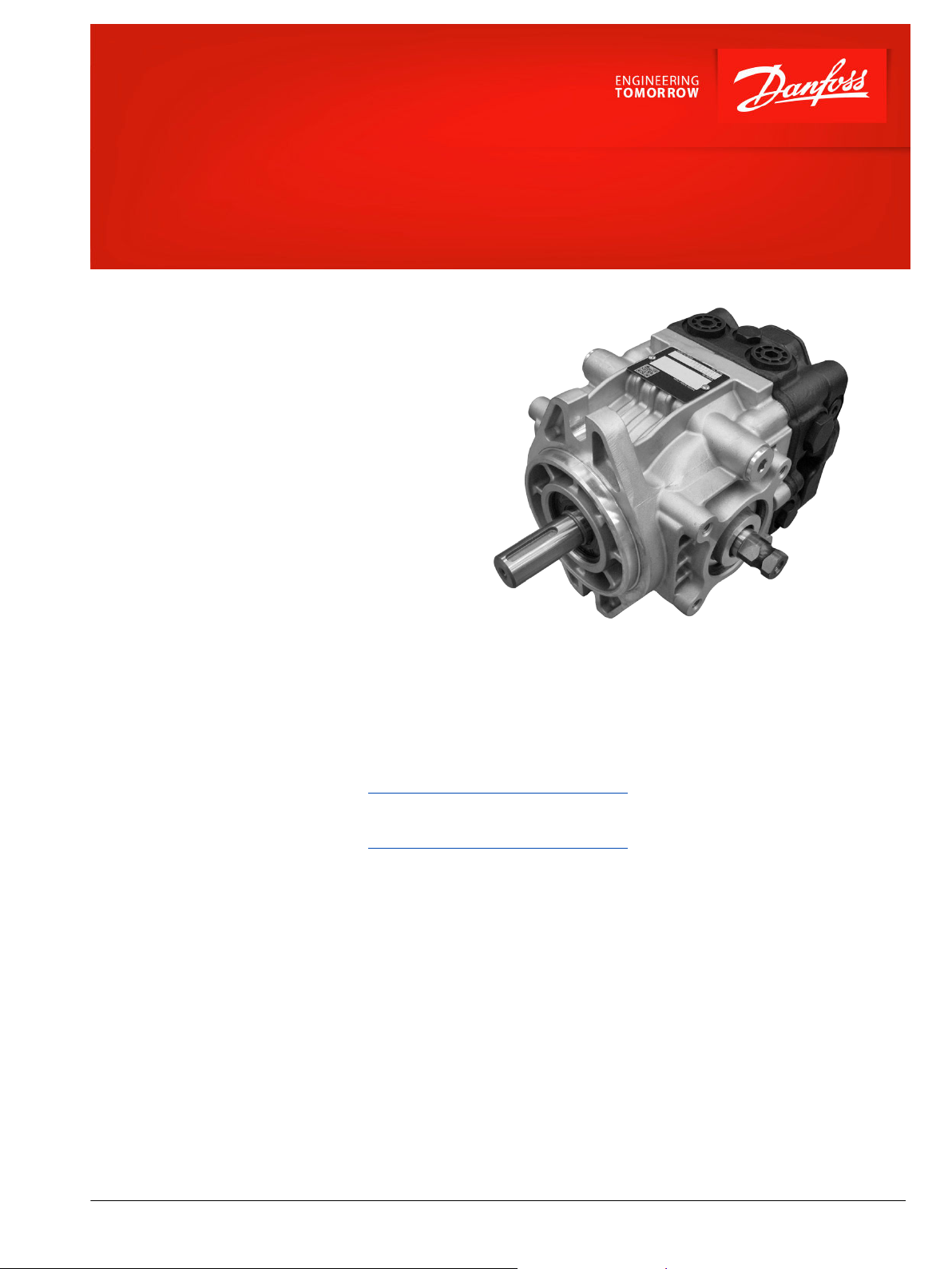
DDC Axial Piston Pumps
with Implement Pump, 20/24 cm³
For more than 40 years, Danfoss has been developing
state-of-the-art components and systems for mobile
machinery used in off-highway operations around the
world. We have become a preferred supplier by
offering the best of what really matters: The hardware
inside your vehicle application.
Implement pump is an integrated charge pump that
can be used for the lightly-loaded external work
function.
Since implement pump has both external gear pump
and charge pump functions, it allows customers to
apply more compact sizing than existing system using
external gear pump.
The DDC pump with implement pump is a high
quality light duty pump which offers expanded
functionality, great total efficiency, low noise, and
easy installation.
The DDC pump is well suited for turf care
applications, compact utility tractors, harvesters, small
rollers, and agricultural vehicles.
Features
Designed for Durability and Flexibility
•
Compact and light weight aluminum
housing
•
Single piece swash plate
Installation and Packaging Benefits
•
Compact design minimizes installation
space requirements
•
High corner power
Optimized for Direct Displacement
Control
Options
•
Gerotor implement pump
•
Loop bypass valve
•
High Pressure Relief Valve (HPRV) and
Charge Pressure Relief Valve (CPRV)
•
SAE A and SAE B Mounting Flange
Comprehensive technical literature is
online at www.danfoss.com
©
Danfoss | July 2019 L1528780 | AI00000205en-000202 | 1
Page 2
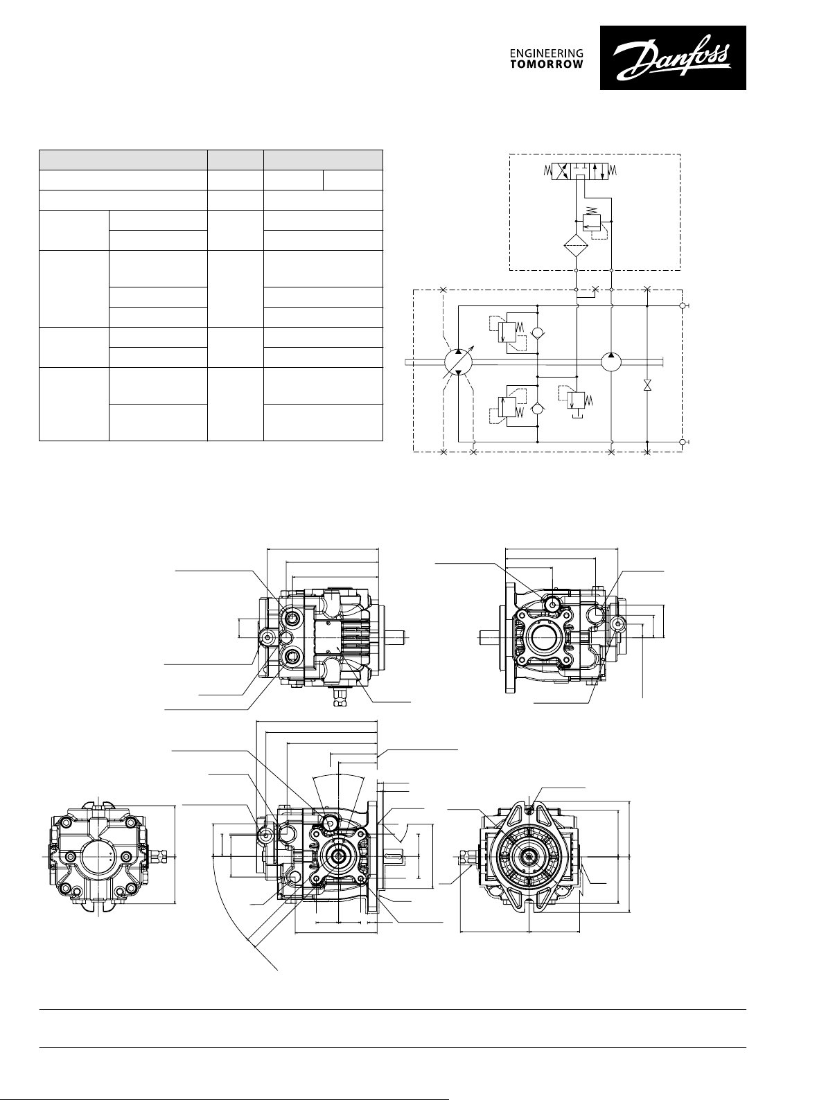
Technical Specifications
A
B
M3 DE
MA
MB
L1L3L2
S
P400052
80.4
±1.5
74.5 ±1.5
System Port “A”
Name Plate
Paint Free
Charge Pressure
Relief Valve
Port ISO 11926-1 -7/8-14
System Port “B”
Port ISO 11926-1 -7/8-14
With Implement Pump
(No Aux-Pad)
Port ISO 11926-1 -9/16-18
Charge Gage Port “M3” Or
Implement return Port “E”
51.5
±0.8
35±0.8
32.5±0.8
32.5±0.8
190.5±1.2
175.5±1.2
142±1.8
74±0.8
60.94±0.8
CCW
CW
18°
Max Disp
18°
Max Disp
1.5
±0.5
9.7
0
-0.5
Mounting Flange
Flange 101-2
Per ISO 3019-1 (SAE B)
Paint
Free
8x M8x 1.25
13 Full Thread
Depth
R0.75 Max
6
.
1
0
1
Ø
0
5
0
.
0
-
2x35±0.82x35±0.8
45°±5°
15
±1
129.5±1.2
2x 35±0.8
2x 35
±0.8
Bypass
Valve
2x17
+0.06
-0.04
4x45°
±3°
Paint
Free
Paint
Free
73±0.3
73
±0.3
87
±1.5
87±1.5
Ø120
2x Ø14.3
±1.5
108
±0.8
79.2
±1.5
+0.3
-0.1
P400138
175.5±1.2
146
±1.2
2x 136
±1.2
2x 30±0.5
Case Drain Port “L1”
Port ISO 11926-1 3/4-16
High Pressure
Relief Valve
Implement Return
Port “E”Or Charge Gage
Port “M3”
Port ISO
11926-1 -9/16-18
177
±1.2
142±1.2
74±0.8
21.5
±0.8
35
±0.8
51.5±0.8
Case Drain Port “L2”
Port ISO 11926-1
3/4-16
High Pressure
Relief Valve
Implement
Discharge Port “D”
Port ISO
11926-1 -9/16-18
Features Unit Value
Displacement cm3 [in3] 20 [1.22] 24 [1.46]
Weight (w/charge pump) kg [lb] 11 [24.3]
Input Speed Rated min
Maximum 4500
System
Pressure
Max. Working
*
Pressure
-1
4000
(rpm)
bar [psi] 300 [4350]
Max. pressure 345 [5004]
Min. Low Loop 4 [58]
Case
Pressure
Implement
Pressure
Rated bar [psi] 1.5 [21.7]
Maximum 3 [43.5]
Maximum Working
**
Pressure
Maximum Pressure
bar [psi] 70 [1015]
85 [1230]
(absolute)
*
Applied pressures above maximum working pressure requires Danfoss
application approval.
**
Continuous operation at absolute implement pump relief pressure =
Short term t < 30sec
Dimensions
Schematic
Danfoss can accept no responsibility for possible errors in catalogues, brochures and other printed material. Danfoss reserves the right to alter its products without notice. This also applies to products
already on order provided that such alterations can be made without subsequent changes being necessary in specifications already agreed.
All trademarks in this material are property of the respective companies. Danfoss and the Danfoss logotype are trademarks of Danfoss A/S. All rights reserved.
2 | © Danfoss | July 2019 L1528780 | AI00000205en-000202
 Loading...