

Service Manual
Axial Piston Pumps
DDC20/24
www.danfoss.com
Service Manual
DDC20/24 Axial Piston Pumps
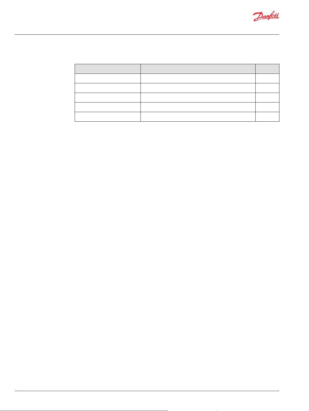
Revision history Table of revisions
Date Changed Rev
August 2019 Added DDC24 0401
August 2017 change charge pump housing 0302
March 2015 add implement pump option CA
March 2014 Danfoss layout BA
September 2011 First printing AA
2 | © Danfoss | August 2019 L1120413 | AX00000135en-000401

Service Manual
DDC20/24 Axial Piston Pumps
Contents
Introduction
Overview..............................................................................................................................................................................................4
Warranty.............................................................................................................................................................................................. 4
General instructions........................................................................................................................................................................ 4
Remove the unit.......................................................................................................................................................................... 4
Keep it clean..................................................................................................................................................................................4
Lubricate moving parts.............................................................................................................................................................4
Replace all O-rings and gaskets............................................................................................................................................. 4
Secure the unit.............................................................................................................................................................................5
Safety Precautions............................................................................................................................................................................5
Unintended machine movement..........................................................................................................................................5
Flammable cleaning solvents.................................................................................................................................................5
Fluid under pressure..................................................................................................................................................................5
Personal safety............................................................................................................................................................................. 5
Gauge port locations and installation
Gauge port locations and sizes- with Aux pad...................................................................................................................... 6
Gauge port locations and sizes- with Gerotor....................................................................................................................... 7
Gauge port locations and sizes- with Implement pump....................................................................................................8
Adjustments
Pump adjustment.............................................................................................................................................................................9
Standard Procedures.......................................................................................................................................................................9
Charge pressure relief valve......................................................................................................................................................... 9
High pressure relief valve............................................................................................................................................................10
Loop flushing valve.......................................................................................................................................................................11
Troubleshooting
Troubleshooting overview......................................................................................................................................................... 12
System operating hot...................................................................................................................................................................12
Transmission operating normally in one direction only..................................................................................................12
System noise or vibration........................................................................................................................................................... 12
System will not operate in either direction.......................................................................................................................... 12
Sluggish system response...........................................................................................................................................................13
Minor repair
Charge pump...................................................................................................................................................................................14
Implement pump...........................................................................................................................................................................16
Shaft and shaft seal....................................................................................................................................................................... 17
High pressure relief valve (HPRV).............................................................................................................................................21
Charge pressure relief valve (CPRV)........................................................................................................................................ 22
Loop flushing valve.......................................................................................................................................................................23
Bypass valve.....................................................................................................................................................................................24
Optional coupling..........................................................................................................................................................................25
Torque charts
Charge pump fastener and torque chart.............................................................................................................................. 26
Implement pump fasteners and torque chart.....................................................................................................................26
Gerotor plugs and torque........................................................................................................................................................... 27
Auxiliary pad plug sizes and torque chart.............................................................................................................................28
Implement pump plug sizes and torque chart................................................................................................................... 29
©
Danfoss | August 2019 L1120413 | AX00000135en-000401 | 3

Service Manual
DDC20/24 Axial Piston Pumps
Introduction
Pump service overview
This manual includes information on maintenance, troubleshooting, and minor repair of DDC20/24
pumps.
Performing minor repairs may require removal from the vehicle/machine. Thoroughly clean the unit
before beginning maintenance or repair activities. Since dirt and contamination are the greatest enemies
of any type of hydraulic equipment, follow cleanliness requirements strictly. This is especially important
when changing the system filter and when removing hoses or plumbing.
A worldwide Global Service Partner Network is available for major repairs. Major repairs require the
removal of the unit’s endcap, which voids the warranty unless done by a Global Service Partner. Danfoss
Global Service Partners are trained by the factory and certified on a regular basis. You can locate your
nearest Global Service Partner using the distributor locator at www.danfoss.com.
For detailed technical information, refer to the Technical Information manual.
Warranty
Performing maintenance, and minor repairs according to the procedures in this manual will not affect
your warranty. Major repairs requiring the removal of the units endcap voids the warranty unless
completed by a Danfoss Global Service Partner.
General instructions
Remove the unit
Prior to performing major repairs, remove the unit from the vehicle/machine. Chock the wheels on the
vehicle or lock the mechanism to inhibit movement. Be aware that hydraulic fluid may be under high
pressure and/or hot. Inspect the outside of the pump and fittings for damage. Cap hoses and plug ports
after removal to prevent contamination.
Keep it clean
Cleanliness is a primary means of assuring satisfactory pump life, on either new or repaired units. Clean
the outside of the pump thoroughly before disassembly. Take care to avoid contamination of the system
ports. Cleaning parts using a clean solvent wash and air drying is usually adequate.
As with any precision equipment, keep all parts free of foreign materials and chemicals. Protect all
exposed sealing surfaces and open cavities from damage and foreign material. If left unattended, cover
the pump with a protective layer of plastic.
Lubricate moving parts
During assembly, coat all moving parts with clean hydraulic fluid. This assures that these parts are
lubricated during start-up.
Replace all O-rings and gaskets
Danfoss recommends you replace all O-rings, seals, and gaskets during repair.Lightly lubricate all O-rings
with clean petroleum jelly prior to assembly. Grease must be soluable in hydraulic fluid.
4 | © Danfoss | August 2019 L1120413 | AX00000135en-000401

W
W
W
W
Service Manual
DDC20/24 Axial Piston Pumps
Introduction
Secure the unit
For major repair, place the unit in a stable position with the shaft pointing downward. It is necessary to
secure the pump while removing and torquing components and fasteners.
Safety Precautions
Always consider safety precautions before beginning a service procedure. Protect yourself and others
from injury. Take the following general precautions whenever servicing a hydraulic system.
Unintended machine movement
Unintended movement of the machine or mechanism may cause injury to the technician or bystanders.
To protect against unintended movement, secure the machine or disable/disconnect the mechanism
while servicing.
Warning
Flammable cleaning solvents
Warning
Some cleaning solvents are flammable. To avoid possible fire, do not use cleaning solvents in an area
where a source of ignition may be present.
Fluid under pressure
Warning
Escaping hydraulic fluid under pressure can have sufficient force to penetrate your skin causing serious
injury and/or infection. This fluid may also be hot enough to cause burns. Use caution when dealing with
hydraulic fluid under pressure. Relieve pressure in the system before removing hoses, fittings, gauges, or
components. Never use your hand or any other body part to check for leaks in a pressurized line. Seek
medical attention immediately if you are cut by hydraulic fluid.
Personal safety
Warning
Protect yourself from injury. Use proper safety equipment, including safety glasses, at all times.
©
Danfoss | August 2019 L1120413 | AX00000135en-000401 | 5
System port A
System port B
O-ring plug 9/16-18UNF-2B
L3 Case Drain
O-ring Plug 3/4-16UNF-2B
M3 Charge gauge / E - Charge inlet
O-ring plug 9/16-18UNF-2B
MA system pressure gauge port
O-ring plug 9/16-18UNF-2B
MB system pressure gauge port
O-ring plug 9/16-18UNF-2B
L1 Case Drain
O-ring Plug 3/4-16UNF-2B
L2 Case Drain
O-ring Plug 3/4-16UNF-2B
M3 Charge gauge / E - Charge inlet
Service Manual
DDC20/24 Axial Piston Pumps
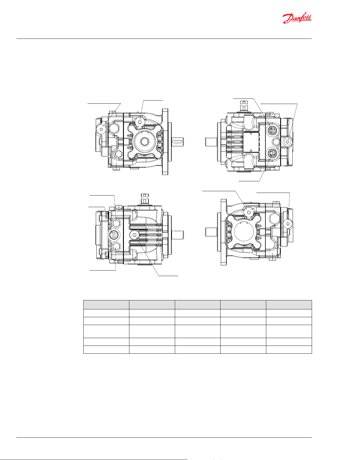
Gauge port locations and installation
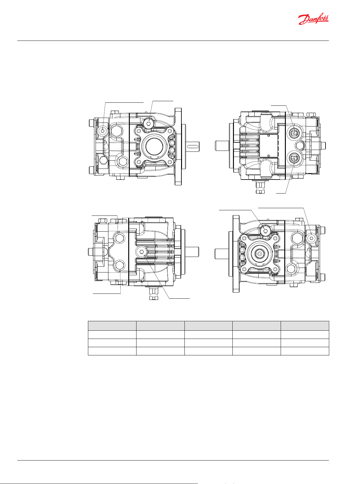
DDC20/24 gauge port locations and sizes- with Aux pad
The following drawing and table show the gauge port locations and gauge sizes needed.
DDC20/24 with aux pad
Port Information
Port Identifier Port Size Wrench Size Pressure Obtained Gauge Size, bar [psi]
L1/L2/L3 3/4-16 UNF 5/16 inch internal hex Case Drain 10 [100]
MA/MB 9/16-18 UNF 11/16 hex wrench System Pressure 500 [5000]
M3/E 9/16-18 UNF 1/4 inch internal hex Charge Pressure 50 [1000]
6 | © Danfoss | August 2019 L1120413 | AX00000135en-000401
S -Charge
suction port
MA
system pressure gage port
O-ring plug 9/16-18UNF-2B
L3 Case Drain
O-ring Plug 3/4-16UNF-2B
M3 Charge Pressure Gauge Port
O-ring Plug 7/16-20UNF-2B
L1 Case Drain
O-ring Plug 3/4-16UNF-2B
MB
system pressure gage port
O-ring plug 9/16-18UNF-2B
Service Manual
DDC20/24 Axial Piston Pumps
Gauge port locations and installation
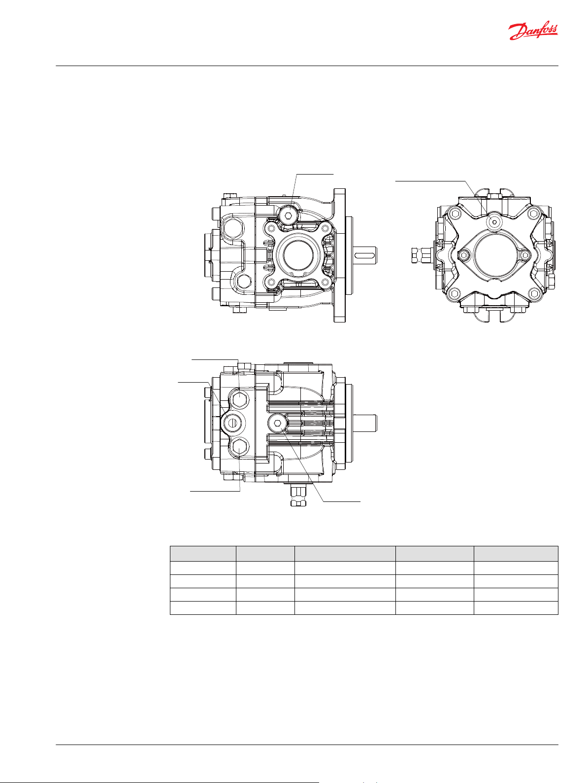
DDC20/24 gauge port locations and sizes- with Gerotor
The following drawing and table show the gauge port locations and gauge sizes needed.
DDC20/24 with gerotor
Port Information
Port Identifier Port Size Wrench Size Pressure Obtained Gauge Size, bar [psi]
L1/L2/L3 3/4-16 UNF 5/16 inch internal hex Case Drain 10 [100]
MA/MB 9/16-18 UNF 11/16 hex wrench System Pressure 500 [5000]
S 7/8-14 UNF N/A (plastic shipping plug) Charge Inlet 2 [30] Vacuum
M3 7/16-20 UNF 3/16 inch internal hex Charge Pressure 50 [1000]
©
Danfoss | August 2019 L1120413 | AX00000135en-000401 | 7
S -Charge
suction port
M3 Charge Pressure Gauge Port
O-ring Plug 9/16-18UNF-2B
L3 Case Drain
O-ring Plug 3/4-16UNF-2B
L1 Case Drain
O-ring Plug 3/4-16UNF-2B
MA system pressure gage port
O-ring plug 9/16-18UNF-2B
MB system pressure gage port
O-ring plug 9/16-18UNF-2B
A System Port
B System Port
L2 Case Drain Port
O-ring plug 3/4-16UNF-2B
D Implement Discharge
O-ring plug 9/16-18UNF-2B
M3 Charge Gauge/
O-ring plug 9/16-18UNF
E Implement Return
E Implement Return
Service Manual
DDC20/24 Axial Piston Pumps
Gauge port locations and installation
DDC20/24 gauge port locations and sizes- with implement pump
The following drawing and table show the gauge port locations and gauge sizes needed.
DDC20/24 with implement pump
Port Information
Port Identifier Port Size Wrench Size Pressure Obtained Gauge Size, bar [psi]
L1/L2/L3 3/4-16 UNF 5/16 inch internal hex Case Drain 10 [100]
MA/MB 9/16-18 UNF 11/16 hex wrench System Pressure 500 [5000]
S 7/8-14 UNF N/A (plastic shipping
D 9/16-18 UNF 1/4 inch internal hex Implement Pressure 100 [2000]
M3/E 9/16-18 UNF 1/4 inch internal hex Charge Pressure 50 [1000]
plug)
Charge Inlet 2 [30] Vacuum
8 | © Danfoss | August 2019 L1120413 | AX00000135en-000401

C
Service Manual
DDC20/24 Axial Piston Pumps
Adjustments
Pump adjustment
This section offers instruction on adjustment of pump components. Read through the entire topic before
beginning a service activity. Refer to Gauge port locations and installation for location of gauge ports and
suggested gauge size.
Standard Procedures
Contamination can damage internal components and void the manufacturer’s warranty. Take
precautions to ensure system cleanliness when removing and reinstalling system lines
1. With the prime mover off, thoroughly clean the outside of the pump.
2. If removing the pump from the machine, tag each hydraulic line connected to the pump. If hydraulic
lines are disconnected, plug each open port, to ensure that dirt and contamination do not get into
the pump.
3. Ensure the surrounding areas of the machine are clean and free of contaminants such as dirt and
grime.
4. Look at the hydraulic fluid for signs of system contamination, oil discoloration, foam in the oil, sludge,
or small metal particles.
5. If there are signs of contamination in the hydraulic fluid, drain the hydraulic system, replace all filters,
flush the lines and fill the system with the proper hydraulic fluid.
Caution
DDC20/24 charge pressure relief valve adjustment
The following procedure explains how to check for proper operation of the charge pressure relief valve.
Charge pressure is the measured pressure minus case drain pressure.
1. Install a 50 bar [1000 psi] pressure gauge at the charge pressure gauge port. Install a 10 bar [100 psi]
gauge at one of the case pressure ports. Operate the system with the pump in neutral (zero
displacement) when measuring charge pressure.
Pressure listed in model code assumes a charge flow of 15 l/min [4 US gal/min], and are referenced to
case pressure. At higher charge flows, the charge pressure will rise over the rated setting.
2. The table shows the acceptable pump charge pressure range for some nominal charge relief valve
settings (refer to model code located on serial number plate).
3. If measured pressure is not correct, disassemble the valve and look for signs of wear or
contamination. Refer to the Torque charts chapter for wrench sizes and torque settings.
4. If the valve is worn, replace the entire valve assembly.
5. Re-check the charge pressure setting.
©
Danfoss | August 2019 L1120413 | AX00000135en-000401 | 9

P109626
J320
L200
L100
QJ040
Service Manual
DDC20/24 Axial Piston Pumps
Adjustments
6. When the desired charge pressure setting is achieved, remove the gauges.
Charge pressure relief valve
Charge pressure
Model code Charge pressure
07 7 bar ± 1 bar
18 18 bar ± 1.5 bar
1
The shown values are calculated by subtracting the case pressure port gauge reading from the charge pressure
gauge reading.
Factory set at 1800 min-1 (rpm) with a reservoir temperature of 50° C [120° F].
DDC20/24 high pressure relief valve (HPRV) adjustment
The HPRV valves are set at the factory. No adjustment is possible.
If you suspect a HPRV valve malfunction, replace valve with identical relief setting and test operation of
pump. Refer to Removal for replacement procedures.
When replacing or opening an HPRV, check for proper pump operation by cycling through its full
operating range.
1
10 | © Danfoss | August 2019 L1120413 | AX00000135en-000401

P109625
QJ020
J140
QJ020
J150
P100
P110
N100
N110
J220
H150
H200
H100
H200
H150
J230
Service Manual
DDC20/24 Axial Piston Pumps
Adjustments
HPRV valve locations
DDC20/24 loop flushing valve adjustment
The loop flushing valve is not adjustable.
If the loop flush valve is malfunctioning, disassemble the valve and check for worn, damaged or scored
components. Replace parts if necessary. Refer to Removal for replacement procedures.
Loop flushing valve locations
©
Danfoss | August 2019 L1120413 | AX00000135en-000401 | 11

Service Manual
DDC20/24 Axial Piston Pumps
Troubleshooting
Troubleshooting overview
This section serves as a guide for identifying and resolving undesirable system conditions.
Please observe the safety concerns listed in Safety Precautions and the precautions related to relevant
equipment when resolving system issues.
DDC20/24 system operating hot
Cause Problem Solution
Oil level in reservoir. Insufficient hydraulic fluid will not meet cooling demands of
Heat exchanger. Heat exchanger not sufficiently cooling the system. Check air flow and input air temperature for heat exchanger.
Charge pressure. Low charge pressure will overwork system. Measure charge pressure. Inspect and/or replace charge relief
Charge pump inlet
vacuum.
System relief
pressure settings.
System pressure. Frequent or long term operation over system relief setting will
system.
High inlet vacuum will overwork system. A dirty filter will
increase the inlet vacuum. Inadequate line size will restrict flow.
If the system relief valves are worn, contaminated, or valve
settings are too low, the relief valves will be overworked.
create heat in system
Fill reservoir to proper level.
Clean, repair or replace heat exchanger.
valve. Inspect charge pump. Repair or replace charge pump.
Check charge inlet vacuum. If high, inspect inlet filter and
replace as necessary. Check for adequate line size, length or
other restrictions
Verify settings of high pressure relief valves and replace valves
as necessary.
Measure system pressure. If pressure is too high, reduce loads.
DDC20/24 transmission operating normally in one direction only
Cause Problem Solution
Control linkage Control linkage operating improperly Repair/replace control linkage
High pressure relief
valve
Malfunctioning HPRV can affect one direction while the other
functions normally.
Exchange the high pressure relief valves. If the problem
changes direction, replace the valve that does not operate
correctly. Settings may be different for forward/reverse.
DDC20/24 system noise or vibration
Cause Problem Solution
Oil level in reservoir Low oil level leads to cavitation. Fill reservoir.
Aeration of the oil/
pump inlet vacuum
Cold oil If oil is cold, it may be too viscous for proper function and cause
Pump inlet vacuum High inlet vacuum causes noise/cavitation. Check that inlet line is not restricted and is proper size. Check
Shaft couplings A loose shaft coupling will cause excessive noise. Replace loose shaft coupling.
Shaft alignment Misaligned shafts creates noise Align shafts.
Charge/High
pressure relief
valves
Air in system decreases efficiency of units and controls. Air in
system is indicated by excessive noise in pump, foaming in oil,
and hot oil.
cavitation
Unusual noise may indicate sticking valves. Possible
contamination.
Find location where air is entering into the system and fix.
Check that inlet line is not restricted and is proper size.
Allow the oil to warm up to its normal operating temperature
with engine at idle speed.
filter and bypass valves (if present).
Clean/replace valves and test pump. May be a normal
condition.
DDC20/24 system will not operate in either direction
Cause Problem Solution
Oil level in reservoir Low oil level leads to cavitation. Fill reservoir.
Open bypass valve If bypass valve is open, the system loop will be depressurized. Close bypass valve.
12 | © Danfoss | August 2019 L1120413 | AX00000135en-000401

Service Manual
DDC20/24 Axial Piston Pumps
Troubleshooting
Cause Problem Solution
Low charge
pressure with pump
in neutral
Low charge
pressure with pump
in stroke
Pump charge relief
valve.
Charge pump inlet
filter.
Charge pump. A malfunctioning charge pump will provide insufficient charge
System pressure Low system pressure does not provide enough power to move
High pressure relief
valves
Control Linkage Linkage operating improperly Repair/replace control linkage
Low charge pressure insufficient to recharge system loop Measure charge pressure with the pump in neutral. If pressure is
Low charge pressure resulting from elevated loop leakage. Isolate pump from motor by blocking system ports. With pump
A pump charge relief valve that is leaky, or contaminated, or set
too low will depressurize the system.
A clogged filter will under supply system loop. Inspect filter and replace if necessary.
flow.
load
Defective high pressure relief valves cause system pressure to
be low
low, go to Pump charge relief valve
in partial stroke and engaged for only a few seconds, check
pump charge pressure. Low charge pressure indicates a
malfunctioning pump. Continue to next step. Good charge
pressure indicates a malfunctioning motor or other system
component. Check motor charge relief operation (if present).
Replace pump charge relief valve as necessary
Repair or replace the charge pump.
Measure system pressure. Continue to next step.
Replace high pressure relief valves.
DDC20/24 sluggish system response
Cause Problem Solution
Oil level in reservoir Low oil level causes slower system response Fill reservoir
High pressure relief
valves
Low prime mover
speed
Air in system Air in system will produce slower system response Fill tank to proper level. Cycle system slowly for several minutes
Pump inlet vacuum Inlet vacuum is too high resulting in reduced system pressure. Measure charge inlet vacuum. Inspect line for proper sizing.
Bypass valve Slightly activated bypass valve will cause cross port leakage. Verify that the bypass valve is closed and that the valve is
Incorrect system pressures will affect system reaction time. High
pressure relief valve with orifice may affect system reaction
time.
Low engine speed will reduce system performance Adjust engine speed
Replace high pressure relief valves
to remove air from system
Replace filter. Confirm proper bypass operation.
seating properly. Clean, repair, or replace it as necessary.
©
Danfoss | August 2019 L1120413 | AX00000135en-000401 | 13

P109624
Flat
side
Counterclockwise rotation
Flat
side
Clockwise rotation
Service Manual
DDC20/24 Axial Piston Pumps
Minor repair
Charge pump
DDC20/24 charge pump disassembly
Charge pump cover orientation
Please note the orientation of the charge pump during disassembly (clockwise and counterclockwise).
1. Position the pump with the shaft end pointing down.
2. Mark the orientation of the charge pump cover on the endcap for proper reassembly.
3. Remove cap screws (K200). Remove the charge pump cover (K150).
4. Remove and discard O-ring (K100).
5. Remove gerotor (K010). Push out the drive pin (K050).
DDC20/24 machined surface inspection
Inspect all machined surfaces for wear or damage. If any nicks, scratches or wear are found replace
the cover and/or gerotor.
DDC20/24 charge pump assembly
1. Install drive pin (K050) into the shaft.
2. Lubricate and install the gerotor (K010).
3. Lubricate and install O-ring into cover (K100).
4. Install the housing in its original position (K150).
5. Install screws (K200). Torque screws per table.
14 | © Danfoss | August 2019 L1120413 | AX00000135en-000401

P109623
K200
K100
K010
K050
K150
Service Manual
DDC20/24 Axial Piston Pumps
Minor repair
DDC20/24 Remove charge pump
©
Danfoss | August 2019 L1120413 | AX00000135en-000401 | 15
Charge pump cover mounting bolts
Item Wrench size Torque
K200 6 mm internal hex 20 N•m [15 lbf•ft]

K210
K200
K250
K100
K110
K010
K150
Service Manual
DDC20/24 Axial Piston Pumps
Minor repair
Implement pump
DDC20/24 implement pump removal
1. Position the pump with the shaft end pointing down.
2. Remove cap screws (K200/K210). Remove the implement pump housing (K150).
3. Remove and discard O-ring (K100/K110).
4. Remove gerotor (K010). Remove locating pins (K250) from housing.
Remove implement pump
Implement pump cover bolts
Item Description Wrench size Torque
K200 Cap screw 8 mm internal hex 60 N・m [44 lbf・ft]
K210 Cap screw 8 mm internal hex 39 N・m [29 lbf・ft]
16 | © Danfoss | August 2019 L1120413 | AX00000135en-000401

C
Service Manual
DDC20/24 Axial Piston Pumps
Minor repair
DDC20/24 machined surface inspection
Inspect all machined surfaces for wear or damage. If any nicks, scratches or wear are found replace
the housing and/or gerotor.
DDC20/24 implement pump assembly
1. Install locating pins (K250) into the endcap.
2. Lubricate and install gerotor (K010).
3. Lubricate and install O-ring (K100/K110) into housing (K150).
4. Install housing (K150).
5. Install screws (K200/K210). Torque screws per table.
Shaft and shaft seal
DDC20/24 shaft seal removal
1. Orient pump with the shaft pointing up.
2. Using a retaining ring pliers, remove retaining ring (F125).
3. Remove the shaft seal (F120) and discard.
Caution
Do not damage the housing bore, shaft or bearing when removing the shaft and shaft seal.
Carefully drive a small sheet-metal screw into the shaft seal to facilitate removal. Be careful not to
damage the bearing below the seal. Attach a slide hammer or appropriate puller to the screw head
and pull to remove the seal.
©
Danfoss | August 2019 L1120413 | AX00000135en-000401 | 17

F125
F115
F120
F110
F105
F100
Service Manual
DDC20/24 Axial Piston Pumps
Minor repair
Remove Seal, Shaft, Bearing
18 | © Danfoss | August 2019 L1120413 | AX00000135en-000401

C
Service Manual
DDC20/24 Axial Piston Pumps
Minor repair
DDC20/24 shaft removal
1. Using a retaining ring pliers, remove retaining ring (F115).
2. Pull the shaft (F100), with bearing (F105), out of the pump. If necessary, tap lightly on the shaft to
dislodge it from the internal pump components.
Moving the pump with the shaft removed may dislodge the rotating group making reassembly
impossible without removing the endcap.
3. If replacing the bearing (F105), remove retaining ring (F110) using a retaining ring pliers.
4. Press on the inner race to remove the bearing (F105) from the shaft.
DDC20/24 shaft inspection
1. Ensure the shaft and its splines are straight and free of damage or heavy wear.
2. Inspect the shaft surface where it meets the shaft seal.
3. Replace the shaft if a groove exists at the sealing land surface that may let dirt into or hydraulic fluid
out of the unit.
4. Clean the sealing area with a nonabrasive material if necessary.
5. Lubricate the shaft with a light coat of hydraulic fluid before assembly.
Caution
DDC20/24 shaft bearing inspection
1. Clean bearing with a solvent and lubricate with hydraulic fluid.
Replace the bearing if issues persist after cleaning.
2. Rotate the bearing in hand. The bearing should rotate smoothly.
3. Inspect for wear, or pitting.
If excessive wear is found, replace the bearing.
DDC20/24 shaft and seal assembly
1. Position the pump with the shaft end pointing up.
If previously removed; press bearing onto shaft by applying force to the inner race.
2. Lubricate and install bearing (F105) with hydraulic fluid.
3. Install retaining ring (F110) using retaining ring pliers.
4. Install shaft (F100) with bearing (F105) into housing. Ensure the shaft splines engage the block splines
and the shaft end slides smoothly into the rear bearing. It may be necessary to tap lightly on the shaft
to seat the bearing.
©
Danfoss | August 2019 L1120413 | AX00000135en-000401 | 19

C
F125
F115
F120
F110
F105
F100
Service Manual
DDC20/24 Axial Piston Pumps
Minor repair
5. Using retaining ring pliers, install the retaining ring (F115).
6. Cover shaft splines with an installation sleeve or packaging tape to protect seal during installation.
Lubricate new shaft seal (F120), press into housing until it bottoms out. Press evenly to avoid binding
and damaging the seal.
Do not damage the housing bore, shaft or rear bearing when installing the shaft and shaft seal. All
components should fit together smoothly.
7. Using retaining ring pliers, install the seal retaining ring (F125).
Install shaft /seal/bearing
Caution
20 | © Danfoss | August 2019 L1120413 | AX00000135en-000401

P109625
QJ020
J140
QJ020
J150
P100
P110
N100
N110
Service Manual
DDC20/24 Axial Piston Pumps
Minor repair
High pressure relief valve (HPRV)
DDC20/24 high pressure relief valve (HPRV) removal
1. Mark the location of each valve for proper reassembly.
2. Remove the HPRV valve plugs (J140/J150).
3. Remove and discard O-rings (QJ020).
4. Use a magnet to remove the valves (N110/P110) and springs (N100/P100).
HPRV removal
HPRV plug
Item Wrench size Torque
J140/J150 24 mm 78 N•m [57 lbf•ft]
DDC20/24 high pressure relief valve (HPRV) inspection
Inspect the plug and internal parts of cartridge. If parts are worn or damaged, replace the entire
cartridge.
DDC20/24 high pressure relief valve (HPRV) assembly
1. Lubricate and install new O-rings (QJ020) onto each plug (J140/J150).
2. Verify that the springs (N100/P100) are properly retained on the valves (N110/P110).
3. Install the valves (N110/P110) in their original location as noted during disassembly. Ensure each
valve assembly moves freely in its bore.
4. Torque plugs per table.
5. Operate vehicle/machine through full range of controls to ensure proper operation. Check for leaks.
©
Danfoss | August 2019 L1120413 | AX00000135en-000401 | 21

J320
L200
L100
QJ040
Service Manual
DDC20/24 Axial Piston Pumps
Minor repair
Charge pressure relief valve (CPRV)
DDC20/24 charge pressure relief valve (CPRV) removal
1. Remove the charge pressure relief valve plug (J320). Remove and discard O-ring (QJ040).
2. Use a magnet to remove the spring (L200).
3. Use a magnet to remove the charge relief poppet (L100).
DDC20/24 Charge pressure relief valve (CPRV) inspection
1. Inspect charge pressure relief valve (L100) for wear or damage.
2. Inspect spring (L200).
Replace any damaged components.
DDC20/24 charge pressure relief valve (CPRV) assembly
1. Lubricate and insert the charge relief valve poppet (L100) and spring (L200) into the endcap.
2. Lubricate and install a new O-ring (QJ040).
3. Install the charge relief valve plug (J320). Torque plug per table.
DDC20/24 Remove CPRV
Charge pressure relief valve plug
Item Wrench size Torque
J320 17 mm 24 N•m [18 lbf•ft]
22 | © Danfoss | August 2019 L1120413 | AX00000135en-000401

J220
H150
H150
H100
J230
H200
H200
J230A
J220A
Service Manual
DDC20/24 Axial Piston Pumps
Minor repair
Loop flushing valve
DDC20/24 loop flushing valve removal
1. Remove the loop flushing valve plugs (J220/J230). Remove and discard O-rings (J220A/J230A).
2. Use a magnet to remove the springs (H150) and spring guides (H200).
3. Use a magnet to remove the loop flushing spool (H100).
DDC20/24 loop flushing valve inspection
1. Inspect the springs (H150). Replace the springs if they are warped or bent.
2. Inspect the loop flush spool (H100), replace it if it is worn or damaged.
3. Inspect plugs and spring guides for wear.
4. Install new O-rings to plugs before assembly.
DDC20/24 loop flushing valve assembly
1. Lubricate and insert the loop flushing spool (H100) into endcap.
Ensure the spool moves freely in its bore.
2. Install the spring guides (H200) and springs (H150).
3. Lubricate and install the O-rings (J220A/J230A) on the plugs.
4. Thread the loop flushing valve plugs (J220/J230) into the endcap and torque plugs per table.
DDC20/24 Remove loop flushing valve
Loop flushing valve plugs
Item Wrench size Torque
J220/J230 11/16 inch 35 N•m [26 lbf•ft]
©
Danfoss | August 2019 L1120413 | AX00000135en-000401 | 23

M200
M110
M130
M120
M110
M120
M130
M100
Service Manual
DDC20/24 Axial Piston Pumps
Minor repair
Bypass valve
DDC20/24 bypass valve removal
1. Remove the bypass valve (M100).
2. Remove and discard the O‑rings (M130 and M110) and the backup ring (M120).
DDC20/24 bypass valve inspection
1. Inspect the valve. If the bypass valve is damaged, replace it.
2. Replace O-rings and back-up ring before assembly.
DDC20/24 bypass valve assembly
1. Lubricate and install new O-rings (M130 and M110) and backup ring (M120) onto cartridge.
2. Install the bypass valve (M100/M200). Torque valve per table.
DDC20/24 Remove bypass valve
Bypass valve plug
Item Wrench size Torque
M100/M200 17 mm 12 N•m [9 lbf•ft]
24 | © Danfoss | August 2019 L1120413 | AX00000135en-000401

P108 580E
J538
Coupling
Service Manual
DDC20/24 Axial Piston Pumps
Minor repair
Optional coupling
DDC20/24 optional coupling removal
Remove the coupling (J538).
DDC20/24 coupling inspection
Inspect the coupling. If the coupling is damaged, replace it.
DDC20/24 coupling assembly
Lubricate and install the coupling (J538).
DDC20/24 Remove coupling
©
Danfoss | August 2019 L1120413 | AX00000135en-000401 | 25

J550
K200
J550
P108803
K200
K210
Service Manual
DDC20/24 Axial Piston Pumps
Torque charts
DDC20/24 charge pump fasteners and torque chart
Aux pad (left) and gerotor (right)
Item Fastener Wrench size Torque
K200 Charge pump cover
J550 Endcap/charge pump cover
mounting bolt
6 mm internal hex 20 N•m [15 lbf•ft]
8 mm internal hex 39 N•m [29 lbf•ft]
mounting bolts
DDC20/24 implement pump fasteners and torque chart
Item Fastener Wrench size Torque
K200 Charge pump cover
K210 Endcap/implement pump
mounting bolt
8 mm internal hex 60 N・m [44 lbf・ft]
8 mm internal hex 39 N・m [29 lbf・ft]
housing mounting bolt
26 | © Danfoss | August 2019 L1120413 | AX00000135en-000401

MA
L3
M3
L1
MB
M200
J140
J320
J220
W
Service Manual
DDC20/24 Axial Piston Pumps
Torque charts
DDC20/24 Gerotor- plug sizes and torque chart
Warning
Do not over torque the case drain plugs (L1, L2, L3)
Item Plug Port dimensions Wrench size Torque
J140/J150 HPRV 3/4-16 UNF 24 mm 78 N•m [57 lbf•ft]
L1/L2/L3 Case drain 3/4-16 UNF 5/16 inch internal hex 29 N•m [21 lbf•ft]
J220/J230 Loop flushing valve plug 9/16-18 UNF 11/16 inch internal hex 35 N•m [26 lbf•ft]
M100/M200 Bypass valve 9/16-18 UNF 17 mm 12 N•m [9 lbf•ft]
J320 CPRV 1/2-20 UNF 17 mm 24 N•m [18 lbf•ft]
MA/MB System Pressure Gauge Ports 9/16-18 UNF 11/16 inch 35 N•m [26 lbf•ft]
M3 Charge Pressure Gauge Port 7/16-20 UNF 3/16 inch internal hex 19 N•m [14 lbf•ft]
©
Danfoss | August 2019 L1120413 | AX00000135en-000401 | 27

J150
J320
M100
J220
L3
M3 /
E
MA
MB
L1
L2
M3
J140
J230
W
Service Manual
DDC20/24 Axial Piston Pumps
Torque charts
DDC20/24 aux pad plug sizes and torque chart
Warning
Do not over torque the case drain plugs (L1, L2, L3).
Item Plug Port dimensions Wrench size Torque
J140/J150 HPRV 3/4-16 UNF 24 mm 78 N•m [57 lbf•ft]
M3/E Charge gauge/
L1/L2/L3 Case drain 3/4-16 UNF 5/16 inch internal hex 30 N•m [22 lbf•ft]
J220/J230 Loop flushing valve
M100/M200 Bypass valve 9/16-18 UNF 17 mm 12 N•m [9 lbf•ft]
J320 CPRV 1/2-20 UNF 17 mm 24 N•m [18 lbf•ft]
MA/MB System Pressure
Charge inlet
plug
Gauge Ports
9/16-18 UNF 1/4 inch internal hex 35 N•m [26 lbf•ft]
9/16-18 UNF 11/16 inch internal
9/16-18 UNF 11/16 inch 35 N•m [26 lbf•ft]
hex
35 N•m [26 lbf•ft]
28 | © Danfoss | August 2019 L1120413 | AX00000135en-000401

J140
J320
M200
L3
M3 / E
MA
MB
L1
J150
M3 / E
D
L2
W
Service Manual
DDC20/24 Axial Piston Pumps
Torque charts
DDC20/24 implement pump plug sizes and torque chart
Warning
Item Plug Port dimensions Wrench size Torque
J140/J150 HPRV 3/4-16 UNF 24 mm 78 N•m [57 lbf•ft]
M3/E Charge gauge/Implement
L1/L2/L3 Case drain 3/4-16 UNF 5/16 inch internal hex 29 N•m [21 lbf•ft]
M200 Bypass valve 9/16-18 UNF 17 mm 12 N•m [9 lbf•ft]
J320 CPRV 1/2-20 UNF 17 mm 24 N•m [18 lbf•ft]
MA/MB System Pressure Gauge Ports 9/16-18 UNF 11/16 inch 35 N•m [26 lbf•ft]
D Implement discharge 9/16-18UNF 1/4 inch internal hex 35 N•m [26 lbf•ft]
Do not over torque the case drain plugs (L1, L2, L3).
9/16-18 UNF 1/4 inch internal hex 35 N•m [26 lbf•ft]
return
©
Danfoss | August 2019 L1120413 | AX00000135en-000401 | 29

Danfoss
Power Solutions GmbH & Co. OHG
Krokamp 35
D-24539 Neumünster, Germany
Phone: +49 4321 871 0
Danfoss
Power Solutions ApS
Nordborgvej 81
DK-6430 Nordborg, Denmark
Phone: +45 7488 2222
Danfoss
Power Solutions (US) Company
2800 East 13th Street
Ames, IA 50010, USA
Phone: +1 515 239 6000
Danfoss
Power Solutions Trading
(Shanghai) Co., Ltd.
Building #22, No. 1000 Jin Hai Rd
Jin Qiao, Pudong New District
Shanghai, China 201206
Phone: +86 21 3418 5200
Products we offer:
Hydro-Gear
www.hydro-gear.com
Daikin-Sauer-Danfoss
www.daikin-sauer-danfoss.com
DCV directional control
•
valves
Electric converters
•
Electric machines
•
Electric motors
•
Hydrostatic motors
•
Hydrostatic pumps
•
Orbital motors
•
PLUS+1® controllers
•
PLUS+1® displays
•
PLUS+1® joysticks and
•
pedals
PLUS+1® operator
•
interfaces
PLUS+1® sensors
•
PLUS+1® software
•
PLUS+1® software services,
•
support and training
Position controls and
•
sensors
PVG proportional valves
•
Steering components and
•
systems
Telematics
•
Danfoss Power Solutions is a global manufacturer and supplier of high-quality hydraulic and
electric components. We specialize in providing state-of-the-art technology and solutions
that excel in the harsh operating conditions of the mobile off-highway market as well as the
marine sector. Building on our extensive applications expertise, we work closely with you to
ensure exceptional performance for a broad range of applications. We help you and other
customers around the world speed up system development, reduce costs and bring vehicles
and vessels to market faster.
Danfoss Power Solutions – your strongest partner in mobile hydraulics and mobile
electrification.
Go to www.danfoss.com for further product information.
We offer you expert worldwide support for ensuring the best possible solutions for
outstanding performance. And with an extensive network of Global Service Partners, we also
provide you with comprehensive global service for all of our components.
Local address:
Danfoss can accept no responsibility for possible errors in catalogues, brochures and other printed material. Danfoss reserves the right to alter its products without notice. This also applies to products
already on order provided that such alterations can be made without subsequent changes being necessary in specifications already agreed.
All trademarks in this material are property of the respective companies. Danfoss and the Danfoss logotype are trademarks of Danfoss A/S. All rights reserved.
©
Danfoss | August 2019 L1120413 | AX00000135en-000401
 Loading...