

Page 1
テクニカルインフォメーション
DDC アキシャルピストンポンプ
サイズ 20/24
daikin-sauer-danfoss.com
Page 2
テクニカルインフォメーション DDC アキシャルピストンポンプ サイズ 20/24
改訂履歴 改訂表
日付 変更済み 改訂
February 2022
December 2021
November 2021
October 2021
September 2021
March 2021
January 2021
November 2020
August 2020
June 2020
August 2019
June 2019
December 2018
February 2017
January 2016
April 2015
デテントの追加
設計仕様の修正
LFV に追記
CPRV に表追加
CPRV とモデルコード L の修正
入力軸 AB, BB, DB の修正
機能仕様の修正
作動油の選択修正
チャージ圧設定の更新
カタログ番号の変更:'BC00000191' から'BC152886484876'に。
軽微な修正
サイズ 24 追加
軽微な修正
チャージポンプハウジングの変更
SAE-A、13T 補助パッドオプションを追加
モデルコード更新
0309
0308
0307
0306
0305
0304
0303
0302
0301
0201
0105
0104
0103
0102
0101
BB
March 2015
March 2013
November 2011
October 2011
インプリメントポンプと SAE A マウントフランジオプションの追加とダンフォスレイアウ
トへの変更 - DITA CMS
塗装とタグ
軽微な修正
初 版
BA
AC
AB
AA
2 BC152886484876ja-000309 • February 2022
Page 3

テクニカルインフォメーション
目次
一般的な説明
技術仕様
運転
DDC アキシャルピストンポンプ サイズ 20/24
設計........................................................................................................................................................................................................5
主な特徴.............................................................................................................................................................................................. 5
代表的なアプリケーション..........................................................................................................................................................5
システム図..........................................................................................................................................................................................6
回路図...................................................................................................................................................................................................7
設計仕様.............................................................................................................................................................................................. 8
機能仕様.............................................................................................................................................................................................. 8
動作パラメータ.................................................................................................................................................................................9
作動油仕様..........................................................................................................................................................................................9
高圧リリーフ/チェックバルブ(HPRV)....................................................................................................................................10
オリフィス付き高圧リリーフ/チェックバルブ............................................................................................................10
バイパス機能...................................................................................................................................................................................11
チャージ圧力リリーフバルブ (CPRV).................................................................................................................................... 12
ループフラッシングバルブ....................................................................................................................................................... 13
コントロール...................................................................................................................................................................................14
ダイレクト容量コントロール..............................................................................................................................................14
コントロール操作の要件.......................................................................................................................................................14
動作パラメータ
システム設計パラメータ
概要..................................................................................................................................................................................................... 15
入力回転数....................................................................................................................................................................................... 15
システム圧力...................................................................................................................................................................................15
チャージ圧力...................................................................................................................................................................................15
チャージポンプ吸入圧力............................................................................................................................................................16
ケース圧力....................................................................................................................................................................................... 16
温度..................................................................................................................................................................................................... 16
粘度..................................................................................................................................................................................................... 16
フィルトレーションシステム ..................................................................................................................................................17
フィルトレーション.....................................................................................................................................................................18
サクションフィルトレーション.........................................................................................................................................18
チャージプレッシャ・フィルトレーション..................................................................................................................18
外部圧力フィルトレーション..............................................................................................................................................19
独立したブレーキシステム....................................................................................................................................................... 19
作動油の選択...................................................................................................................................................................................19
タンク.................................................................................................................................................................................................19
ケースドレン...................................................................................................................................................................................19
チャージポンプ..............................................................................................................................................................................20
チャージポンプのサイズ決定/選択...................................................................................................................................20
チャージポンプ出力流量............................................................................................................................................................20
インプリメントポンプ.................................................................................................................................................................21
ベアリング負荷と寿命.................................................................................................................................................................23
外部ラジアル軸負荷が加わる用途.................................................................................................................................... 23
入力軸...........................................................................................................................................................................................23
軸トルク............................................................................................................................................................................................24
取付フランジ負荷..........................................................................................................................................................................25
オーバーハング負荷モーメントの概算...........................................................................................................................25
システムノイズの理解と最小化.............................................................................................................................................. 26
サイズ計算式...................................................................................................................................................................................27
BC152886484876ja-000309 • February 2022 3
Page 4

テクニカルインフォメーション
目次
モデルコード
外形図
参考文献
DDC アキシャルピストンポンプ サイズ 20/24
モデルコード: A, B, R, C, E, G, M................................................................................................................................................ 28
モデルコード: H, K, F.....................................................................................................................................................................29
モデルコード: J, S, L...................................................................................................................................................................... 30
モデルコード: N, P, Y, Z................................................................................................................................................................31
補助 A パッド付き、チャージポンプなし、左トラニオン、取付フランジ SAE A 構成.....................................32
補助 A パッド付き、チャージポンプなし、左トラニオン、取付フランジ SAE B 構成.....................................34
チャージポンプ付き、補助パッドなし、左トラニオン、取付フランジ SAE A 構成..........................................36
チャージポンプ付き、補助パッドなし、左トラニオン、取付フランジ SAE B 構成..........................................38
インプリメントポンプ付き、補助パッドなし、左トラニオン、取付フランジ SAE A 構成............................ 40
インプリメントポンプ付き、補助パッドなし、左トラニオン、取付フランジ SAE B 構成.............................42
オプション: デテント...................................................................................................................................................................44
入力軸: AA, BA, DA..................................................................................................................................................................... 45
入力軸: AB, BB, DB...................................................................................................................................................................... 46
入力軸: AC, BC, DC......................................................................................................................................................................47
補助取付パッド..............................................................................................................................................................................48
文献..................................................................................................................................................................................................... 50
4 BC152886484876ja-000309 • February 2022
Page 5
Bypass valve
SlipperValve plate
Trunnion
Charge pump
Needle bearing
Piston
Swashplate
Check and high pressure relief valve
Input
shaft
Ball bearingCharge pressure relief valve
Endcap
P400023
テクニカルインフォメーション
一般的な説明
設計
主な特徴
DDC アキシャルピストンポンプ サイズ 20/24
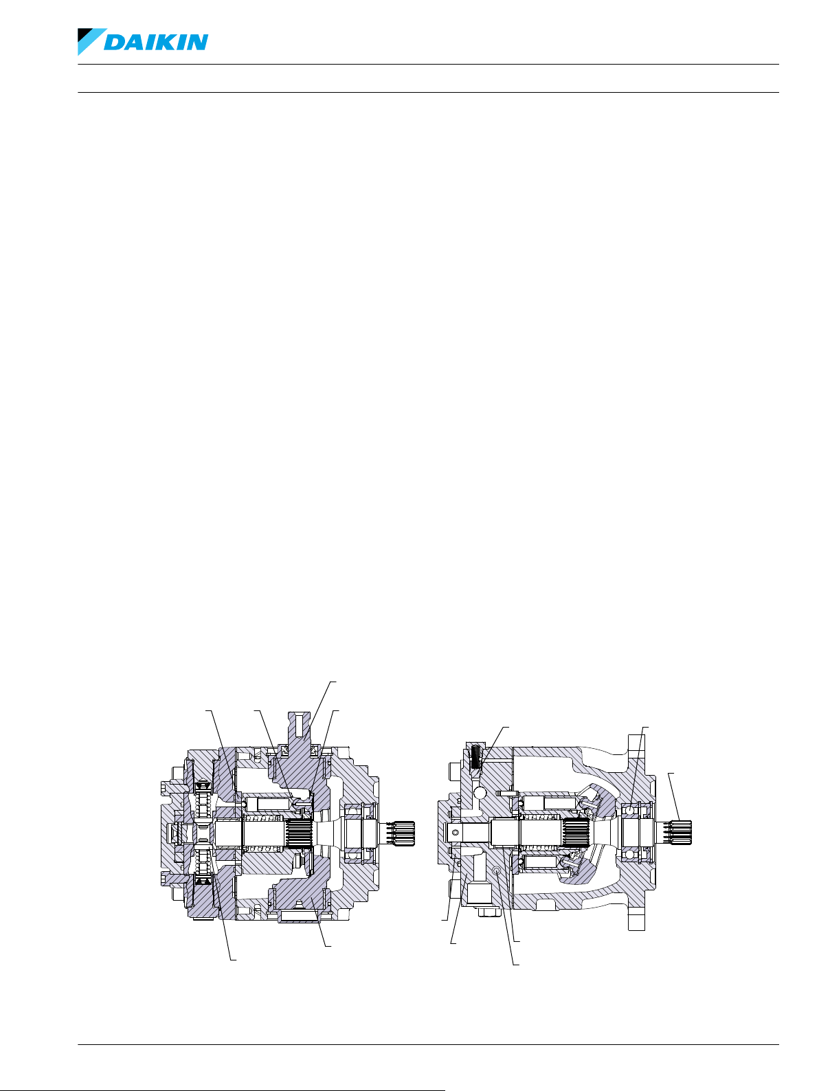
DDC はコンパクトで軽量な可変容量形アキシャルピストンポンプで、閉回路の低~中負荷アプリケーシ
ョン用に設計されています。DDC は先進のスリッパ―ピストン設計によるダイレクト可変容量形ポン
プです。流量はゼロから最大容量まで無断階に調整が可能です。吐出し方向は斜板をニュートラル(流
量ゼロ)から選択可能な 2 つの位置に傾けることで制御します。吐出し方向を反転すると、モータの回
転方向が逆転します。
•
容量 20/24 cm3/rev [1.22/1.46 in3/rev]
•
オプションのバイパスバルブとループフラッシングバルブ
•
オプションの内蔵型チャージポンプ/インプリメントポンプ
•
コンパクトでクラス最高の定格圧力と耐久性
•
低騒音
•
ワールドワイドなサポート
•
取付フランジ(SAE-A / B)
代表的なアプリケーション
DDC
ポンプ断面図
•
芝刈り機
‒
グリーンモア
‒
ゼロターンモア
‒
ローダ
•
ユーティリティ車両(特殊車両・特定用途車両)
•
コンパクト農業機械
•
小型締固め機
•
小型建設機械
BC152886484876ja-000309 • February 2022 5
Page 6
Variable
displacement
pump
Input
shaft
Cylinder
block
assembly
High pressure relief/
check valves
Loop flushing valve
OMR
orbital
motor
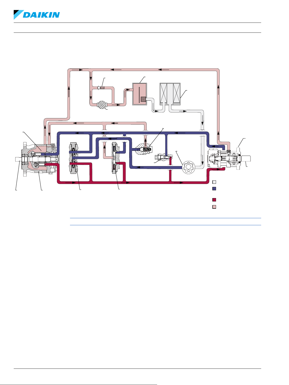
Suction flow
Working Loop (High Pressure)
Case flow
Working Loop (Low Pressure) and
Charge Pressure
Output
shaft
Filter
Charge
pump
Reservoir
Heat
exchanger
Heat exchanger
bypass
Charge pressure relief
valve
Bypass
valve
P400024
テクニカルインフォメーション
一般的な説明
システム図
DDC アキシャルピストンポンプ サイズ 20/24
ループフラッシングバルブとチャージポンプを 1 台のポンプで併用することはできません。
6 BC152886484876ja-000309 • February 2022
Page 7
A
B
M3
MA
MB
L1
L3
L2
S
P400025
テクニカルインフォメーション
一般的な説明
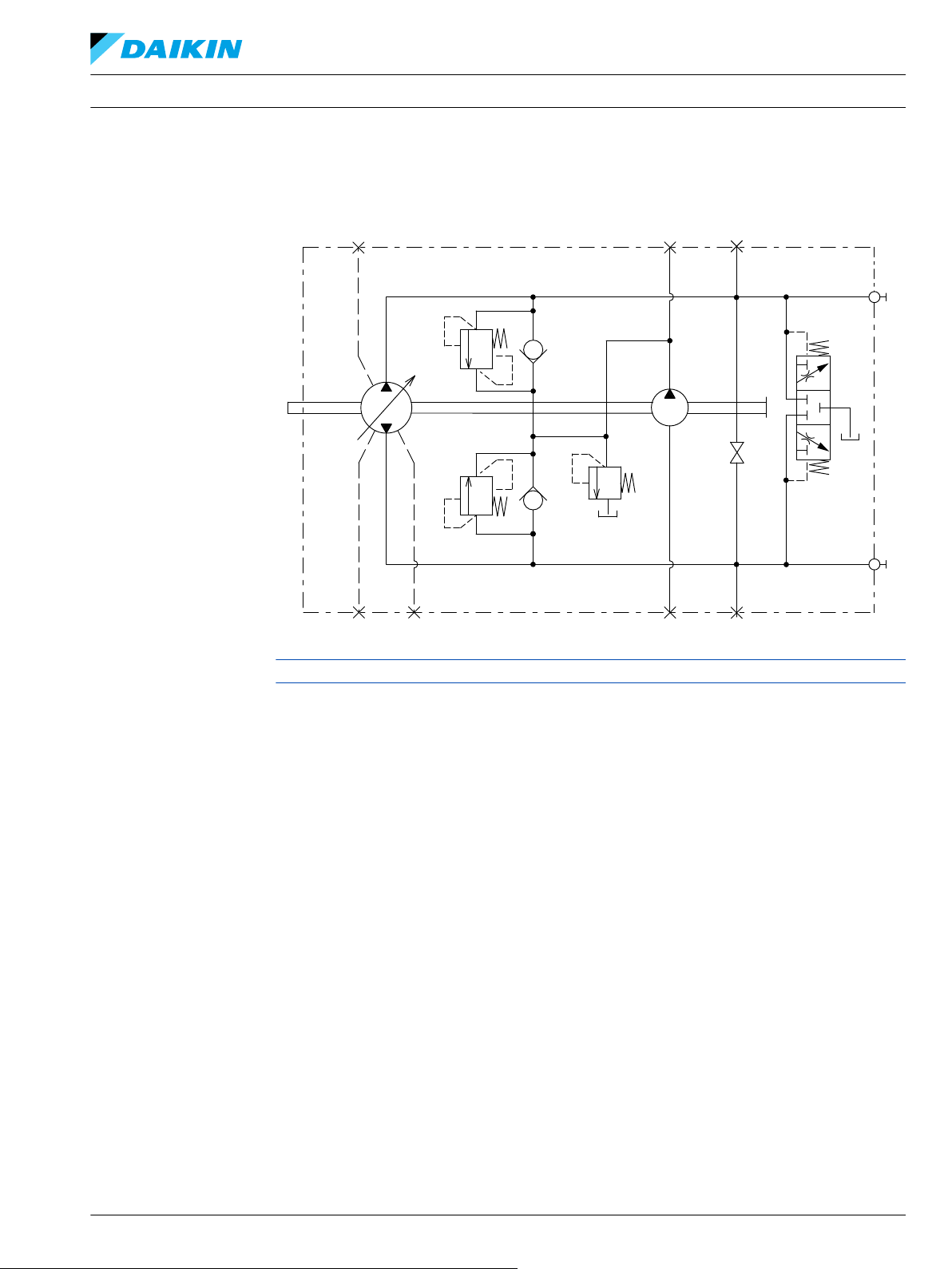
回路図
DDC アキシャルピストンポンプ サイズ 20/24
ループフラッシングバルブとチャージポンプを 1 台のポンプで併用することはできません。
BC152886484876ja-000309 • February 2022 7
Page 8

テクニカルインフォメーション DDC アキシャルピストンポンプ サイズ 20/24
技術仕様
設計仕様
概要 DDC ポンプ
設計 ジャーナルトラニオン設計の可変容量形アキシャルピストンポンプ
入力回転方向 時計回りまたは反時計回り
ポンプ取付位置は任意です。しかし推奨されるトラニオンの位置は側面または下部です。
トラニオンを上部にして設置すると、シャフトの周りに水や埃がたまりやすくなり、シャ
フトシールの劣化を早める可能性があります。
推奨する取付け位置
フィルトレーション構成 吸い込みまたはチャージプレッシャ・フィルトレーション
他のシステム要件 独立ブレーキシステム、適切なタンク容量及び熱交換器
コントロールタイプ ダイレクト容量コントロール
機能仕様
入力軸の垂直取付は可能です。ケースは常に作動油で満たしてください。複数のポンプを
取付ける場合は、出力流量の大きいものから入力ソースに向かって配置することを推奨し
ます。
これらのガイドラインに適合していない場合は弊社にご相談ください。
機能
1
容量
回転部品の質量慣性モーメント
チャージポンプ付
乾燥重量
インプリメントポンプ付
補助パッド付
作動油量 ケースのみ
取付フランジ
単位
cm3/rev [in3/rev]
kg•m2 [slug•ft2] 0.0009 [0.0006]
kg [lb]
liter [US gal] 0.7 [0.1]
ISO3019-1 フランジ 101-2 (SAE B), ボルト 2 本
ISO3019-1 フランジ 82-2 (SAE A), ボルト 2 本
DDC20 DDC24
0-20.0 [0-1.22] 0-24.0 [0-1.46]
10 [22.1]
11 [24.3]
12 [26.4]
ISO 3019-1, 外径 22mm-4 (SAE B, 13 歯)
力シャフト外径、スプライン、キーシャフト
2
ISO 3019-1, 外径 22mm-1 (ストレートキー, Ls)
ISO 3019-1, 外径 22mm-1 (ストレートキー, 特別な長さ)
ISO 3019-1, フランジ 82 - 2, 外径 16 mm - 4
メトリックネジ・アキシャル補助取付フランジ、
軸外径およびスプライン
(SAE A, 9 歯)
ISO 3019-1, フランジ 82 - 2, 外径 19 mm - 4
(SAE A, 11 歯)
吸入口
メインポート形状
ISO 11926-1, 7/8 -14 (SAE O リングボス)
ISO 11926-1, 7/8 -14 (SAE O リングボス) ツインポート, ラジ
アル
ケースドレンポート L1, L2 , L3 ISO 11926-1, 3/4 -16 (SAE O リングボス)
その他のポート
外形図
(32 ページ) を参照。
顧客取付部ネジ メトリック締結
1
斜板の最大角度は 18 度です。
2
マウンティングフランジ SAE A 用
外形図
(32 ページ) を参照。
8 BC152886484876ja-000309 • February 2022
Page 9
テクニカルインフォメーション DDC アキシャルピストンポンプ サイズ 20/24
技術仕様
動作パラメータ
以下の使用の定義は、こちらを参照してください。
機能 単位 DDC ポンプ
内部チャージ供給での最
1
低。
入力回転数
外部チャージ供給最低圧
定格
最高
推奨最高使用圧力
システム圧力
許容最高圧力
最低低圧側ループ圧力(ケ
ースとの差圧)
チャージ圧力(最低)
最小(連続)
チャージポンプ吸入圧力
最小値(コールドスタート)
最大
ケース圧力
1
無負荷時。詳細はシステム設計パラメータ
定格
最高
チャージポンプ
min-1(rpm)
bar [psi]
bar@15 lpm [psi/USG] 7 [101]
bar(絶対値)[in Hg vacuum]
bar [psi]
(20 ページ)を参照してください。
動作パラメータ
500
500
4000
4500
300 [4350]
345 [5004]
4 [58]
0.8 [6]
0.2 [24]
2.0
1.5 [21.7]
3 [43.5]
(15 ページ)
作動油仕様
機能
1
粘度
瞬間最低
最低
推奨範囲
最高(コールドスタート)
最低値(コールドスタート)
温度の範囲
3
推奨範囲
最高(連続)
瞬間最高
ISO 4406 の清浄度
能力 (チャージプレッシャー
フィルトレーション(推奨
される ろ過能力最低値)
フィルトレーション)
能力(サクションフィルト
レーション)
推奨される吸入スクリーン
メッシュサイズ
1
瞬間 = 1 回あたり 1 分未満の短い時間で、デューティーサイクルに基づく負荷寿命の 2%を超えないもの
2
コールドスタート= 短時間、3 分以内、p ≤ 50bar[725 psi]、n < 1000 min-1(rpm)
3
もっとも熱いポイント(通常はドレンポート)での温度。
単位 DDC ポンプ
5 [42]
mm2/sec [ SUS]
2
7 [49]
12 - 80 [66 - 370]
1600 [7500]
-20
°C
60 - 85
104
115
22/18/13
β15-20=75(β10≥10)
β x 値
β35-45=75(β10≥2)
µm 100 - 125
BC152886484876ja-000309 • February 2022 9
Page 10
P400026
C
W
テクニカルインフォメーション
DDC アキシャルピストンポンプ サイズ 20/24
運転
高圧リリーフ/チェックバルブ(HPRV)
DDC ポンプは高圧リリーフとチャージチェックバルブの組み合わせが装備されています。高圧リリーフ
バルブ(HPRW)の機能は、過剰なシステム圧力を制限するための圧力制御バルブです。トランスミッ
ションループの両側には、非調整式の高圧リリーフバルブがあります。システム圧力が工場で設定され
た値を超えたとき、チャージラインに作動油が流入します。バルブはシステム圧力とチャージ圧力の差
動圧力デバイスです。チャージチェックバルブは、ループ低圧側の圧力がチャージ圧力以下になると、
作動ループの低圧側にチャージオイルを補充するように作用します。
各システムポートに対して異なる圧力設定が可能です。使用できる HPRV 圧力設定はオーダーコードに
指定されています。
オリフィス付き高圧リリーフ/チェックバルブ
オリフィス付き HPRV バルブはオプションとして用意されています。一部の用途では、ニュートラルの
調整を容易にするためオリフィス付き HPRV/チェックバルブの使用が望ましい場合があります。オリフ
ィスは作動ループ高圧側とチャージギャラリーを接続します。ループのわずかな漏洩により、斜板のニ
ュートラルポジションの不感帯を拡大します。多くの用途では、システムループの片側だけをオリフィ
ス付き HPRV とします。高圧側のオリフィスはシステムの効率を下げ、発熱を増やします。逆駆動側の
みにオリフィスを設けることでシステムの効率低下を最低限に抑えることができます。ダウンヒルクリ
ープの増加がみられることがあります。
高圧リリーフバルブは、下記流量で設定されています。
オリフィスなしチェック/HPRV バルブ
オリフィス付きチェック/HPRV バルブ
注意
高圧リリーフバルブの設定値は、小流量で工場設定されています。高圧リリーフバルブに大流量が流れ
るようなアプリケーションまたは動作状態では、工場で設定した以上の圧力上昇が発生します。このよ
うなアプリケーションレビューについては、弊社までお問い合わせください。オリフィス付き HPRV の
使用により、ダウンヒルクリープが増加することがあります。
警告
予期せぬ車両または機械の動きの危険
車両には、油圧駆動の動力損失時に、車両または機械を停止させその状態に維持するのに十分なブレー
キシステムを、油圧トランスミッションに加えて必ず用意してください。
5 l/min [1.3 US gal/min]
17 l/min [4.5 US gal/min]
10 BC152886484876ja-000309 • February 2022
Page 11
System Loop (Low Pressure)
Bypass Valve
System Loop (High Pressure)
P400027
C
テクニカルインフォメーション
運転
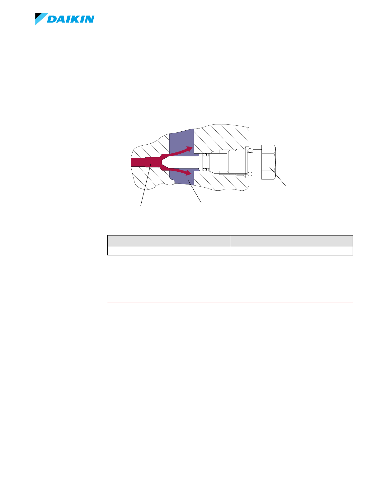
バイパス機能
DDC アキシャルピストンポンプ サイズ 20/24
用途により、ポンプシャフトや原動機を回転させずに機械または機器を移動させることができるよう、
油圧系統をバイパスできることが好ましいことがあります。オプションのバイパスバルブはシステムル
ープの A と B の両側を機械的に接続します。バルブを反時計回りに 3 回転させると、バイパスは完全に
開きます。通常の動作では、このバルブは完全に閉じる必要があります。バイパスバルブの位置は DDC
ポンプ概要図を参照してください。
バイパスバルブのレンチサイズとトルク
レンチサイズ トルク N•m [lbf•ft]
17 mm external 12.0 [9.0]
注意
速度超過や長い移動はポンプやモータの損傷につながります。
バイパス機能使用時は、過剰な速度、車両の長い移動は避けてください。車両を最高速度の 20%超えた
り、3 分間を超えて移動した場合、駆動モータが損傷する可能性があります。
BC152886484876ja-000309 • February 2022 11
Page 12
Charge Pressure
Case Drain
P400028
C
テクニカルインフォメーション
DDC アキシャルピストンポンプ サイズ 20/24
運転
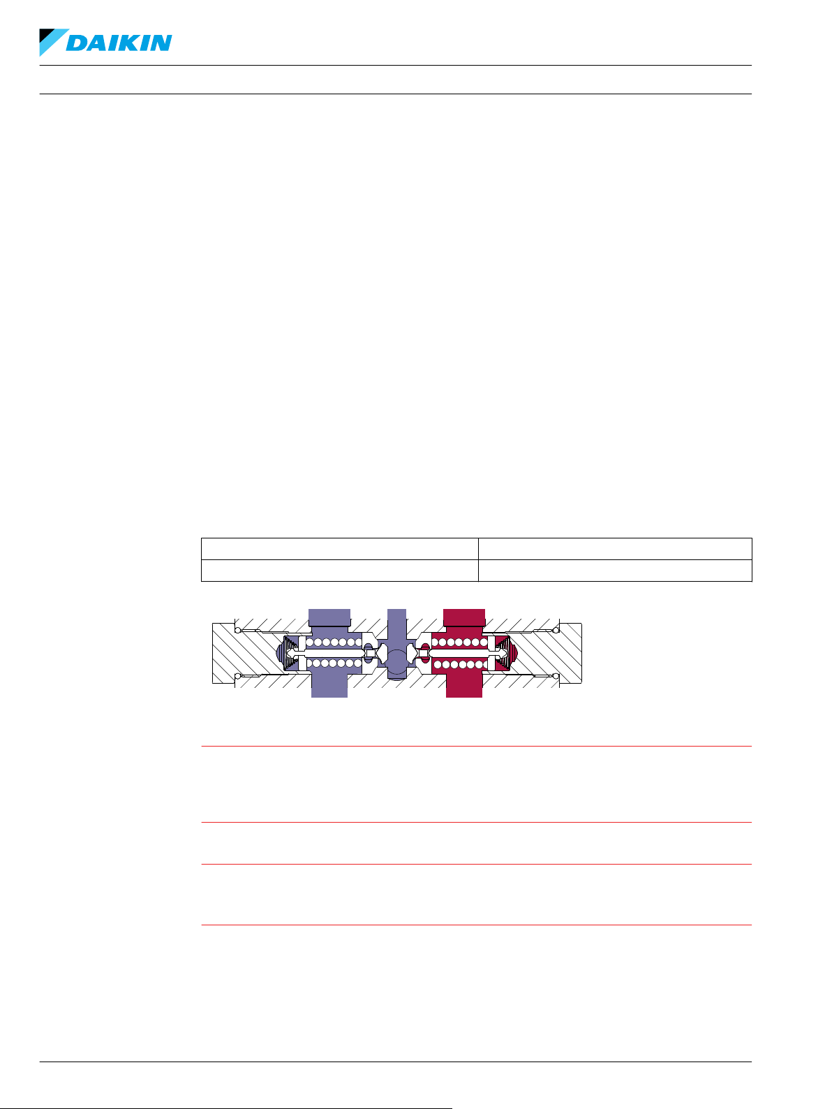
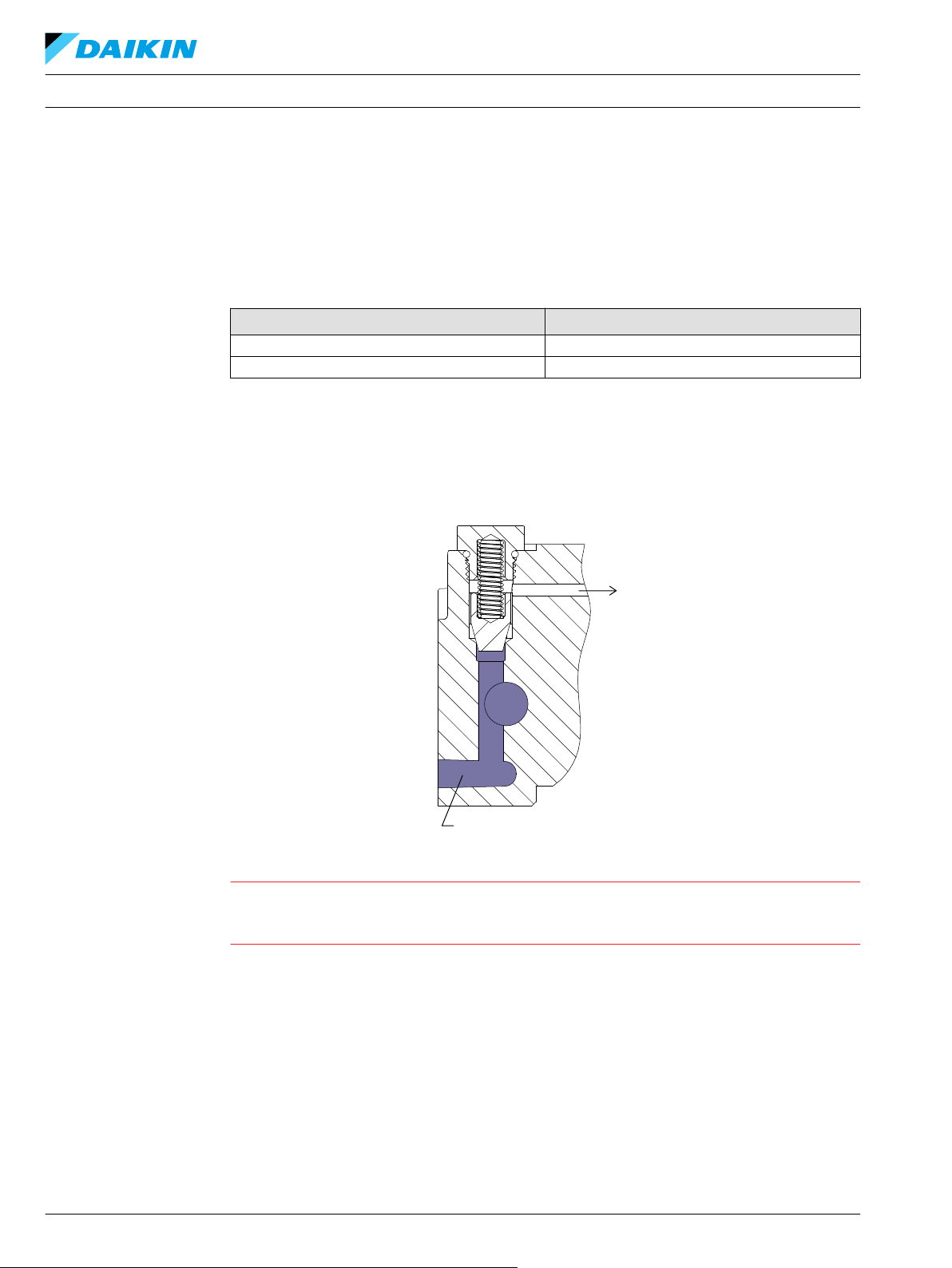
チャージ圧力リリーフバルブ (CPRV)
内蔵チャージ圧力リリーフバルブ(CPRV)は油圧回路内のチャージ圧力を調整します。CPRV は、ケー
ス圧力との差圧を指定レベルに調整する直動型ポペット弁です。
チャージ圧力リリーフバルブの設定圧は、ポンプのモデルコードにより指定されます。チャージポンプ
付きの DDC ポンプでは、CPRV は 1800 rpm にて設定されますが、チャージポンプなしの DDC ポンプで
は外部チャージ流量以下に設定されています。
チャージ圧力設定 [bar] 外部チャージ流量 [L/min]
7 8.6
11, 14, 18, 21 13.5
外部チャージ流量ありの場合の 7 bar チャージ圧力上昇率は、約 0.8 bar/10 L [4.4 psi/US gal]です。
外部チャージ流量ありの場合の 11 bar と 14 bar チャージ圧力上昇率は、約 1.4 bar/10 L [7.7 psi/US gal]
です。
外部チャージ流量ありの場合の 18 bar と 21 bar チャージ圧力上昇率は、約 1.6 bar/10 L [8.8 psi/US gal]
です。
注意
DDC ポンプを可変モータと使用する場合は、チャージ圧力が必要なモーターシフト圧力に適合するか確
認してください。追加のチャージリリーフ設定が利用できるかどうかは弊社の担当者にお問い合わせく
ださい。
12 BC152886484876ja-000309 • February 2022
Page 13
Working Loop (Low Pressure)
Working Loop (High Pressure)
Case
Notched Diameter
P400029
Oil Temp = 50°C (~30 mm2
/S)
P400301
Flow [lpm]
Charge pressure [d bar]
テクニカルインフォメーション
運転
ループフラッシングバルブ
DDC アキシャルピストンポンプ サイズ 20/24
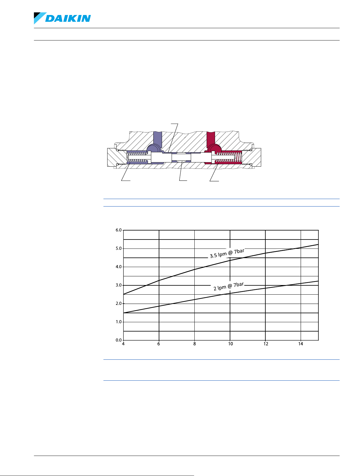
DDC ポンプにはオプションの組み込みループフラッシングがあります。ループフラッシングバルブは、
他のものより速い率で熱と汚染物質をメインループから取り除きます。
DDC ループフラッシングは、バネで中央に位置付けられるシャトルにオリフィスプラグが付いた簡単な
設計です。シャトルはおおよそで移動します。
8 bar [115 psi]フラッシング流量は低ループシステム圧力(チャージ)とプラグのサイズの関数です。
チャージポンプの組合せでは、ループフラッシングバルブは使用できません。
Loop flushing performance
DDC ポンプを外部ループフラッシング・シャトルバルブと共に使用する場合は、ポンプのチャージ設定
がループフラッシング・シャトルバルブの設定と一致していることを確認してください。他のチャージ
リリーフ設定が利用できるかどうかは弊社の担当者にお問い合わせください。
BC152886484876ja-000309 • February 2022 13
Page 14
-50
-40
-30
-20
-10
0
10
20
30
40
50
-20 -15 -10 -5 0 5 10 15 20
<pumping mode>
35 bar
6 bar
50 bar
100 bar
200 bar
300 bar
<a>
<b>
Stroke increasing moment
Stroke increasing moment
Stroke decreasing moment
Stroke decreasing moment
Trunnion moment (N•m)
Angle (deg)
P400030
a b
テクニカルインフォメーション
運転
コントロール
DDC アキシャルピストンポンプ サイズ 20/24
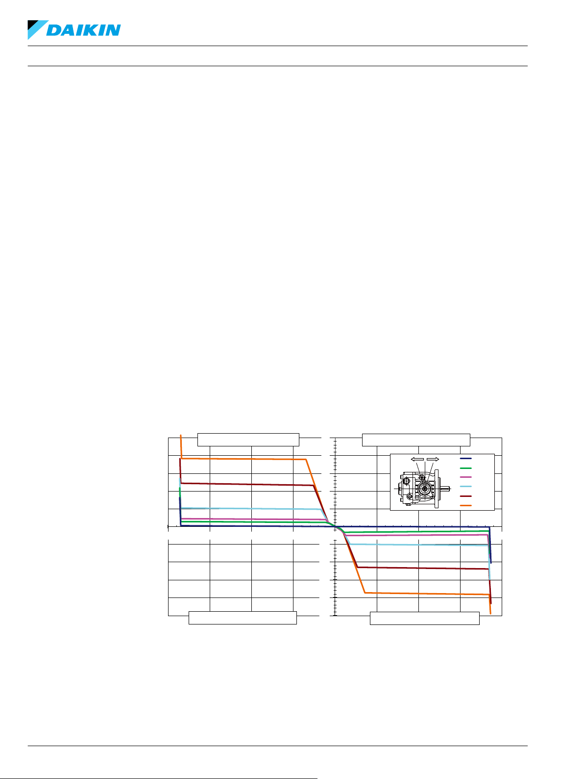
ダイレクト容量コントロール
DDC ポンプはダイレクト容量コントロール(DDC)仕様です。斜板の角度は斜板のトラニオンに取付け
られた制御レバーの接続により直接設定されます。制御レバーを動かすと、容量と吐き出し方向が変わ
ります。
トラ二オンはポンプの右または左に配置できます。
コントロール操作の要件
すべての DDC ポンプは、トランスミッション内の油圧をポンプのコントロールアームに伝達します。
この油圧はコントロールアームのトルクとなります。コントロールアームのトルクの性質と強さは、ト
ランスミッションの動作条件(ポンプの速度、圧力、容量)と DDC のバルブプレートの設計に関係し
ます。通常動作では、コントロールアームのトルクはストロークを減少させ、一方で動的なブレーキ動
作やダウンヒル操作では、ストローク増加のフィードバックにつながります。ドライバーや機械的リン
クは、どのような状態からでもポンプをニュートラルに戻すことができなければなりません。コントロ
ールアームのより低いトルクのオプションについてのさらなるアプリケーションサポートが必要な場合
は、ダンフォスまでご連絡ください。
コントロールレバー(トラ二オン)の最大許容トルクは 79.1 Nm(700 in-lbs)です。トラ二オンへの入
力トルクを制限するため、コントロールレバーにはストッパーが必要となります。斜板の最大角度は+/-
18 度です。
DDC
入力=2000 rpm、温度=50°C、シェルテラス 46 粘度=30m 2/s
ストローク速度=1°/秒、標準 HPRV
ポンプ制御モーメント
14 BC152886484876ja-000309 • February 2022
Page 15
W
テクニカルインフォメーション
動作パラメータ
概要
入力回転数
DDC アキシャルピストンポンプ サイズ 20/24
このセクションは、入力回転数と圧力について限界と動作パラメータについて定義します。
最低回転数はエンジンアイドル状態で推奨される最低入力回転数です。最低回転数以下で運転すると、
潤滑や動力伝達のための十分な流量を維持するためのポンプ能力が制限されます。
定格回転数は最高出力状態で推奨される最高入力回転数です。この回転数以下で運転すれば、十分な製
品寿命が得られます。
最高回転数は許容される最高運転回転数です。最高回転数を超えると、製品寿命を縮め、油圧パワーと
ブレーキ能力の損失が生じる場合があります。どのような運転状況でも、最高回転数制限を超えてはい
けません。
定格回転数と最高回転数の間の運転条件では、最大出力以下に制限し、時間も制限する必要がありま
す。ほとんどの運転システムでは、最高ユニット回転数は、下り坂でのブレーキまたは負の動力状態時
に発生します。
油圧ブレーキで下り坂状態では、原動機はポンプの速度超過を避けるため十分なブレーキトルク能力を
必要とします。これは特にターボチャージのティアーⅣエンジンでは重要になります。
警告
システム圧力
予期せぬ車両または機械の動きの危険
最高回転数を超過すると、油圧駆動ラインの動力とブレーキ能力の損失を招く可能性があります。油圧
駆動の動力損失時に、車両または機械を停止させその状態に維持するのに十分なブレーキシステムを、
油圧トランスミッションに加えて必ず用意してください。
システム圧力はシステムポート A と B の間の差圧です。これは油圧製品寿命に影響する最も有力な変数
です。高負荷からくる高いシステム圧力は、予想寿命を短縮します。油圧製品の寿命は、回転数と、負
荷サイクル分析によってのみ判定できる荷重平均の圧力または通常運転圧力によって決定されます。
アプリケーション圧力とは、ポンプのモデルコードで通常定義される、高圧リリーフ設定値です。これ
は、アプリケーションにおいて駆動系が最大牽引力またはトルクを発生するときにシステムにかかる圧
力です。
推奨最高使用圧力は推奨される最高のアプリケーション圧力です。推奨最高使用圧力は、連続使用圧力
ではありません。アプリケーション圧力またはそれ以下での駆動システムで、この圧力は適切なコンポ
ーネントのサイズ選択により十分な製品寿命が得られます。
許容最高圧力はあらゆる条件で許容される最大のアプリケーション圧力です。推奨最高使用圧力を超え
るアプリケーション圧力は、デューティーサイクル分析と弊社の承認によりのみ可能となります。圧力
スパイクは通常生じるものであり、推奨最高使用圧力を検討する際には考慮する必要があります。
これらすべての圧力限界は、低圧ループ (チャージ) 圧との差圧です。ゲージの値から低ループ圧力を差
し引き、差分を計算します。
最低ループ圧力 (ケース圧力との差圧) は、ループの低圧側で安全な動作状況を維持するために必要な最
低圧力です。
チャージ圧力
内蔵チャージリリーフバルブはチャージ圧力を調整します。チャージ圧力はトランスミッションループ
の低圧側の圧力を維持します。
注文コードに記載されているチャージ圧力設定は、中立、1800 min-1 [rpm] での運転、動粘度 32 mm2/s
[150 SUS] でのポンプのチャージリリーフ弁の設定圧力です。チャージポンプなし (外部チャージ供給)
のポンプは 18.9 l/min [5.0 US gal/min] のチャージ流量と、32 mm2/s [150 SUS] の動粘度で設定されてい
ます。
BC152886484876ja-000309 • February 2022 15
Page 16

C
テクニカルインフォメーション
動作パラメータ
チャージポンプ吸入圧力
ケース圧力
DDC アキシャルピストンポンプ サイズ 20/24
チャージ設定圧力はケース圧力に依存します。
通常の運転温度では、チャージ吸入圧力は、定格チャージ入力圧力 (マイナス圧) 以下にならないように
してください。
最小チャージ吸入圧力 はコールドスタート条件でのみ許可されています。アプリケーションによって
は、エンジンスタート前に (タンク内などの) 作動油を温め、オイルが温まるまで制限された速度でエン
ジンを稼動することを推奨します。
最大チャージポンプ吸入圧力は連続して適用できます。
通常の動作条件下では、定格ケース圧力 以下にしてください。コールドスタートの場合、ケース圧力が
最高ケース圧力を下回るように維持しなければなりません。状況によって、適切なドレン配管を選んで
ください。
注意
構成部品の損傷と油漏れの可能性
決められた限界以上のケース圧力で運転すると、シール、ガスケット、ハウジングを損傷し、外部油漏
れを生じることがあります。チャージ流量とシステム圧力がケース圧力に影響するため、ポンプ性能に
も影響する可能性があります。
温度
粘度
高温限界は、トランスミッションの最も高いポイントに適用します、それは一般にはモータのケースド
レンです。システムは一般に定格温度以下で使用してください。
瞬間最高温度は材料の特性に基づきます、決してこの温度を超えてはいけません。
作動油が低温の場合、トランスミッション部品の耐久性はに影響を与えませんが、流量と動力を伝達す
る作動油の性能に影響を与えることがあります。したがって温度は作動油の流動点より 16 °C [30 °F] 以
上高く維持してください。
最高温度は構成部品の材料の物理特性に関連します。この制限内に作動油を維持するように熱交換器の
サイズを決めてください。弊社はこれらの温度制限を超えないか試験して確認することを推奨します。
オイルの温度と粘度の制限が同時に満たされることを確認してください。
効率 とベアリング寿命を最大化するため、流体粘度が推奨範囲内になるようにしてください。
最低粘度は、周辺温度が最高で険しいデューティーサイクルでの運転の、短時間の使用のみに適用して
ください。
最高粘度はコールドスタート時のみに適用してください。
16 BC152886484876ja-000309 • February 2022
Page 17
テクニカルインフォメーション DDC アキシャルピストンポンプ サイズ 20/24
システム設計パラメータ
フィルトレーションシステム
早期摩耗を防止するため、油圧トランスミッション回路には必ず清浄なオイルを入れてください。通常
の運転条件では、ISO 4406 クラス 22/18/13(SAE J1165)以上のオイル清浄度を管理できるフィルタを
推奨します。これらの清浄レベルは、輸送後の構成部品のハウジング/ケースまたはその他の空洞部に
残された作動油には適用されません。
フィルトレーションにはサクションまたはプレッシャフィルトレーションがあります。フィルタの選択
は、コンタミナントの侵入率、システム内でのコンタミナントの生成、必要なオイル清浄度、望ましい
メンテナンス間隔など多くの要因に依存します。フィルタは、効率と能力の定格パラメータを使用し
て、上記の要件に合うように選定されます。
フィルタ効率は、ベータ比 (βX) で示されます。単純なサクションフィルタを持つ閉回路トランスミッシ
ョンとリターンラインフィルタを持つ開回路システムでは、フィルタのベータ比は、β
2) または、それより良好なことが必要と解っています。同じタンクを使用したシリンダを持つ開回路
と閉回路のシステムでは、より高いフィルタ効率を必要とします。これは共通のタンクを使うギアまた
はクラッチを持ったシステムにも適用されます。これらのシステムでは、フィルタ・ベータ比が β
= 75 (β10 ≥ 10) 以上の、チャージ圧またはリターンフィルタシステムが一般的に必要です。
システムはそれぞれ固有であるため、徹底的なテストと評価プログラムによってのみ、そのフィルトレ
ーション・システムを十分に確認することが可能となります。詳細については Design Guidelines for
Hydraulic Fluid Cleanliness Technical Information, BC152886482150 を参照ください。
清浄度レベルおよび βx比
フィルトレーショ
ン
(推奨される最低
値)
1
フィルタ βx比は ISO 4572 で定義されたフィルタ効率の尺度です。これはフィルター上流の所定の直径(「x」ミク
ロン)より大きな粒子の数に対するフィルター下流の粒子の数の比で定義されます。
1
ISO 4406 の清浄度
効率 (チャージプッレッシャーフィ
ルトレーション)
効率(サクションとリターンライ
ンフィルトレーション)
推奨される吸入スクリーンメッシ
ュサイズ
22/18/13
β
15-20
β-ratio
β
35-45
µm 100 – 125
= 75 (β10 ≥ 10)
= 75 (β10 ≥ 2)
= 75 (β10 ≥
35-45
15-20
BC152886484876ja-000309 • February 2022 17
Page 18

P400032
Reservoir
Filter
with bypass
Charge
pump
Charge relief valve
To pump case
To Low Pressure
side of loop
Strainer
Potential
workfunction
circuit
P400031
テクニカルインフォメーション
システム設計パラメータ
フィルトレーション
DDC アキシャルピストンポンプ サイズ 20/24
サクションフィルトレーション
フィルタはタンクとチャージポンプ吸入口との間に設置します。コールドスタート条件で、吸入圧力の
制限を超えないようにしてください。
サクションフィルトレーション
チャージプレッシャ・フィルトレーション
プレッシャ・フィルトレーション・システムでは、プレッシャ・フィルタはリモートでチャージ供給回
路の下流に取付けられます。プレッシャ・フィルトレーションは、内蔵チャージポンプの有無にかかわ
らず可能です。チャージプレッシャ・フィルトレーション回路で使用するフィルタは、最低 35bar [508
psi] の圧力仕様が必要です。チャージプレッシャ・フィルトレーションを使用する場合には、100 – 125
ミクロン・スクリーンをタンク内またはチャージ吸入口に設置することを推奨します。
フィルタバイパスはフィルタの損傷を防ぐために必要です。目詰まりしたフィルタまたはコールドスタ
ート時に高い圧力損失がある場合には、作動油がフィルタをバイパスすることがあります。オープンバ
イパス状態で長期間の稼働は避けてください。可視的または電気式のバイパス表示器が推奨されます。
適切なフィルタメンテナンスが必須です。
チャージプレッシャ・フィルトレーション
18 BC152886484876ja-000309 • February 2022
Page 19

W
C
テクニカルインフォメーション
システム設計パラメータ
独立したブレーキシステム
作動油の選択
DDC アキシャルピストンポンプ サイズ 20/24
外部圧力フィルトレーション
チャージサプライは補助動作機能または専用ギアポンプ回路から DDC ポンプに供給されます。リモー
トフィルタを通過したあと、油圧は外部チャージ供給ポートからポンプに入ります。
警告
予期せぬ車両または機械の動きの危険
任意の運転モード (正転、ニュートラル、逆転) において、油圧駆動ラインの動力損失により、システム
の油圧ブレーキ能力の損失が生じることがあります。油圧駆動の動力損失時に、車両または機械を停止
させその状態に維持するのに十分なブレーキシステムを、油圧トランスミッションに加えて必ず用意し
てください。
ポンプの定格および性能データは、酸化防止剤、防錆剤、消泡剤入りの作動油を使用して動作した場合
に得られたものです。作動油は、内部部品の磨耗、侵食、および腐食を防止するために、良好な熱安定
性と加水分解に対する安定性を持たなければなりません。
タンク
ケースドレン
注意
決して、異なる種類の作動油を混ぜないでください。
油圧システムのタンクは、すべての動作モード中の最大容量変化に対応し、タンクを通過するオイルの
エアー抜きを促進する必要があります。
推奨される最小合計タンク容量は 1 分あたりの最大チャージポンプ流量の 5/8 で、最小油量は 1/2 分あ
たりの最大チャージポンプ流量の 1/2 です。これは最大戻り流量で混入エアーを除去するために 30 秒
間オイルを滞留させるためです。これは通常、ほとんどのアプリケーションで密閉タンク (通気口なし)
に適用できます。
重力分離を利用し、大きな異物がチャージ吸入ラインに入ることを防ぐため、タンクの底より上にタン
ク出口 (チャージポンプ吸入口) を設置します。出口ポートに 100-125 µm スクリーンフィルタを推奨し
ます。
タンク入口 (オイルのリターン) は通常の液面より下、タンク内に向かって排出するように設置します。
隔壁板 (バッフル) はさらにエアー抜きを促進し、流体のうねり現象を減らします。
ポンプハウジングは常に作動油で満たされていなければなりません。DDC ポンプには 3 つのケースド
レンポートがあり、柔軟なホースの取り回しやポンプの取付けが可能です。一方のケースドレンポート
からのラインをタンクに接続します。ケースドレンオイルは、一般的にはシステムで最も高い油温とな
ります。
BC152886484876ja-000309 • February 2022 19
Page 20

Charge pump Flow (lpm)
Speed min-1(rpm)
0
5
10
15
20
25
30
0 500 1000 1500 2000 2500 3000 3500 4000 4500
P400046
7.5 cm
3
4.8 cm
3
3.1 cm
3
テクニカルインフォメーション
システム設計パラメータ
チャージポンプ
DDC アキシャルピストンポンプ サイズ 20/24
チャージ流量は DDC ポンプで必要です。チャージポンプはシステムの漏れを補うための流量を提供し、
メイン回路内のプラス圧を維持し、冷却とフラッシングのための流量を提供します。
チャージ流量の必要条件とその結果としてのチャージポンプサイズの選択には、多くの要因が影響しま
す。これらの要因には、システム圧力、ポンプ入力回転数、ポンプ斜板角度、作動油の種類、温度、熱
交換器サイズ、油圧ラインの長さとサイズ、補助流量要求、油圧モータタイプなどがあります。アプリ
ケーションで最初に油圧ユニットのサイズを決めて選択する際には、チャージポンプサイズ選択のすべ
ての点を正確に把握するために必要な、すべての情報を入手することは困難な場合が多いです。
通常ではないアプリケーション条件では、チャージポンプサイズ決定のため、より詳細な検討が必要に
なることがあります。チャージ圧力は、トランスミッションへの損傷を防ぐためにあらゆる動作条件で
特定のレベルに維持することが必要です。これを確認するために、実際の動作条件で試験することが推
奨されます。
チャージポンプのサイズ決定/選択
ほとんどのアプリケーションで、一般的なガイドラインでは、チャージポンプ容量はシステムのすべて
のコンポーネントの合計容量の最低 10%が必要とされています。通常ではないアプリケーション条件で
は、必要チャージ流量のより詳細な検討が必要になることがあります。詳細手順については Selection of
Drive line Components, BC157786484430 を参照ください。
チャージポンプ出力流量
次のようなシステム機能と条件では、10% ガイドラインを適用できないことがあります。(ただしこれ
らに限定されません)
•
低入力速度{ 1500 min-1(rpm)未満}での連続運転
•
高衝撃負荷
•
高入力回転数
•
大容量 LSHT モータ
お使いのアプリケーションにこれらの条件が含まれている場合には、アプリケーションの支援のために
ダンフォス社にお問い合わせください。
7 bar [100 psi]
チャージリリーフ設定、
30mm2/s [140SUS]、50 °C [122 °F]
での流量
20 BC152886484876ja-000309 • February 2022
Page 21

Implement pump Flow (lpm)
Implement Pump Pressure (bar)
0
5
10
15
20
25
0 10 20 30 40 50 60 70
P400136
7.5 cm
3
, 3000 min
-1
5.4 cm
3
, 3000 min
-1
7.5 cm
3
, 1800 min
-1
5.4 cm
3
, 1800 min
-1
テクニカルインフォメーション
システム設計パラメータ
インプリメントポンプ
DDC アキシャルピストンポンプ サイズ 20/24
インプリメントポンプは内蔵型のチャージポンプで、軽い負荷の外部動作機能のために使用できます。
インプリメントポンプには外部動作ギアポンプ、チャージポンプ両方の機能があるため、外部のギアポ
ンプを用いる方式よりコンパクトにまとめることができます。
インプリメント回路は、インプリメントポンプからの作動油がコントロールバルブを通りトランスミッ
ションに戻る「オープンセンター」型とする必要があります。
DDC のインプリメント回路では、チャージ(インプリメント)ポンプからの流れはまずインプリメント
回路のコントロールバルブを通り、チャージリリーフ、チャージチェックバルブへ向かいます。インプ
リメント回路は、インプリメントのオイルがトランスミッションに戻るように設計しなければなりませ
ん。お客様はインプリメントのコントロールバルブに加え、インプリメント回路のリリーフバルブを用
意する必要があります。また、インプリメントコントロールバルブとトランスミッションの間にチャー
ジ圧力フィルタを用意し、インプリメント回路のアクチュエータで生じた汚染がチャージ回路に混入す
ることを防止するよう推奨します。
インプリメントポンプ圧力仕様
インプリメントポンプ最高圧力
インプリメントポンプ推奨最高使用圧力(インプルメント回路リリ
ーフ圧力設定)
1
インプリメントポンプリリーフ圧力での連続運転 = 短期 t <30sec
1
bar [psi]
85 [1230]
70 [1015]
11mm2/s [63SUS]、80°C [176°F]
での流量
高圧、高温で入力スピードが低いと流量不足の原因となることがあります。
BC152886484876ja-000309 • February 2022 21
Page 22

A
B
M3 DE
MA
MB
L1
L3
L2
S
P400052
テクニカルインフォメーション DDC アキシャルピストンポンプ サイズ 20/24
システム設計パラメータ
インプリメント回路
-
回路図
22 BC152886484876ja-000309 • February 2022
Page 23
テクニカルインフォメーション DDC アキシャルピストンポンプ サイズ 20/24
システム設計パラメータ
ベアリング負荷と寿命
ベアリング寿命は入力回転数、システム圧力、チャージ圧力、斜板角度、および すべての外部のサイド
またはスラスト負荷に依存します。斜板角度への影響は、容量と方向などに依存します。外部負荷はポ
ンプがサイド/スラスト負荷で駆動(ベルトまたはギア)するアプリケーション、およびポンプと駆動
カップリング間にズレや不適切な同心度がある場合に見られます。すべての外部サイド負荷は、通常、
ポンプのベアリング寿命を減らす方向に作用します。寿命に影響する要因として、この他に作動油の種
類、粘度、清浄度があります。
外部軸負荷のないプロペル駆動の車両で、システム圧力と斜板角度によって方向と大きさが定期的に変
わる場合、通常の B10ベアリングの寿命(90%生存)は、ユニットの油圧負荷寿命を上回ります。
B10 ベアリング寿命
ベアリング寿命
(最大斜板角)
外部ラジアル軸負荷が加わる用途
DDC ポンプは、多少の外部ラジアル荷重を許容できるベアリングで設計されています。外部負荷が存在
する場合、許容されるラジアル軸負荷は、取付フランジからの負荷位置、内部負荷に対する負荷方向、
油圧ユニットの作動圧力に依存します。外部軸負荷が避けられないアプリケーションでは、負荷の適切
な方向選択によってベアリング寿命への影響を最小化できます。最適なポンプの向きは、外部負荷、ポ
ンプ回転グループとチャージポンプの負荷から軸上の正味の負荷から考慮します。
•
正転逆転の斜板操作の量がほぼ同一であるように操作されたポンプのアプリケーションでは、 ベア
リングの寿命は、外部のサイド負荷が回転グループ負荷方向に対して 90° 方向作用するように、外
部のサイド負荷を 90° または 270° 回転位置に作用させることで最適化できます(詳細については以
下の図を参照してください)。
•
斜板が主に(75%以上)ニュートラルの一方の側で運転するようなポンプのアプリケーション(バ
イブレーション、コンベヤー、標準プロペルなど)では、 ベアリングの寿命は、内部回転グループ
負荷方向の反対側の位置に外部のサイド負荷をかけることで、一般的に最適化できます。内部負荷
の方向は、回転と流出システムポートに依存します。
•
DDC ポンプは、偶発的なスラスト負荷に影響されないように、ある程度のスラスト負荷を許容でき
るベアリングで設計されています。スラスト負荷が予想される場合には、許容される負荷は多くの
要因に依存し、アプリケーションで検証を行うことを推奨します。
システム圧力 140 bar 時
7 bar チャージ圧力
1800 rpm
B10 時間
10000
外部負荷が存在する場合には、ベアリング寿命の検証のためにダンフォス社までお問い合わせくださ
い。
スラスト荷重は避けてください。スラスト負荷が想定される場合は、ダンフォス社までご連絡くださ
い。
入力軸
最大許容ラジアル負荷 (Re) は、最大外部モーメント(Me)と取付フランジから負荷までの距離(L)に
基づいています。
Re = Me / L
Me
L
Re
Fa
軸モーメント
フランジ距離
軸に対する外部の力
内部回転グループ負荷(フロー方向により変化)
BC152886484876ja-000309 • February 2022 23
Page 24

270° Re90° Re
0° Re
180° Re
Input shaft
Me
Shaft bearing
LFa
Re
P400033
1200
1000
800
600
400
200
Re N
0 10 20 30 40 50
distance (L) mm
P400034
テクニカルインフォメーション
システム設計パラメータ
DDC アキシャルピストンポンプ サイズ 20/24
軸トルク
最大許容ラジアル負荷
(Re)
ダンフォス社 はラジアル軸荷重のある用途にはクランプタイプのカップリングを推奨します。
連続的に最大許容ラジアル負荷(Re)の 25%超過した外部負荷が適用されたり、または、ほとんどの時間
ポンプ斜板が片側に位置する場合のユニットベアリング寿命の評価についてはダンフォス社にお問い合
わせください。
定格トルクは歯の摩耗の尺度であり、通常のスプライン寿命である 2 x 10⁹ 回転が想定できるトルクレ
ベルを意味します。定格トルクは、スプライン接触面での摩擦係数を低減し酸素を抑制するため、二硫
化モリブデングリスで最小レベルの潤滑で定期的にメンテナンスすることを想定しています。また、嵌
合スプラインは最小硬度 Rc55 の最小硬度とフルスプライン長さを持つことを想定しています。
定格最大トルクは、10 万フル負荷の反転サイクルを考慮したねじり疲労強度に基づきます。ただし、
オイルに浸された環境で動作するスプラインは、コンタミナントのフラッシングに加えて優れた酸素制
限を提供します。オイルに浸されたスプラインの定格トルクは、最大公称定格トルクよりも増加しま
す。オイルに浸されたスプラインとは、ポンプドライブによって駆動されるポンプや、補助パッドに接
続されるポンプスプライン部を意味します。
スプライン嵌合長さを最低でもピッチ円径に維持することによっても、スプライン寿命を最大化できま
す。スプライン嵌合がピッチ円径の 3/4 よりも短いと、高い接触応力でスプラインフレッティングを受
けることになります。
24 BC152886484876ja-000309 • February 2022
嵌合スプラインのピッチ円径との整合は、スプラインドライブ接続の動作寿命を決定する上で重要なも
う 1 つの要因です。
差し込み式
または
柔軟性のない
スプラインドライブ結合すると、シャフトに大きな
Page 25

Center of gravity - pump 1
Center of gravity - pump 2
L 1
L 2
Mounting flange
P400035
テクニカルインフォメーション
システム設計パラメータ
取付フランジ負荷
DDC アキシャルピストンポンプ サイズ 20/24
ラジアル負荷が掛かることがあります。このラジアル負荷は、伝えられたトルクとシャフト偏心に依存
します。スプライン隙間を増加させても、完全にはこの条件を緩和できません。しかし、スプライン隙
間を増加させると、嵌合スプラインとのピッチ円径のズレやラジアル偏心による機械的な干渉を防ぎま
す。ベアリングで支持されるスプラインシャフト間に中間カップリングを追加してスプラインの寿命を
最長にできます。
オーバーハング負荷モーメントの概算
補助ポンプおよび/または従属ポンプが高衝撃負荷が加わると、取付フランジに過剰な負荷がかかるこ
とがあります。激しい共振振動または衝撃を受けるアプリケーションでは、追加のポンプ支持が必要に
なることがあります。複数ポンプ取付け時のオーバーハング負荷モーメントは、以下の式を使用して概
算できます。
MS = GS (W1L1 + W2L2 + ... +WnLn)
MC = GC (W1L1 + W2L2 + ... +WnLn)
ここで、
M
定格負荷モーメント N•m [lbf•in]
C
M
衝撃負荷モーメント N•m [lbf•in]
S
G
定格(振動)加速度 (G’s)* m/s2 [ft/s2]
C
G
最大(衝撃)加速度 (G’s)* m/s2 [ft/s2]
S
W
n 番目のポンプの重量
n
L
取付フランジから n 番目のポンプの重心までの距離
n
(ポンプの重心の位置を求めるには
*
重力加速度
(g = 9.81 m/s2 [32 ft/s2]) に係数を乗じて計算します。この係数はアプリケーションによって
外形図
(32 ページ) を参照してください。)
異なります。
許容オーバーハング負荷モーメント値は次の表を参照してください。
軸負荷パラメータ
BC152886484876ja-000309 • February 2022 25
Page 26

テクニカルインフォメーション
システム設計パラメータ
DDC アキシャルピストンポンプ サイズ 20/24
取付フランジ負荷
定格モーメント (MR) 衝撃負荷モーメント (MS)
N•m [lbf•in] N•m [lbf•in]
SAE B フランジ
SAE A フランジ
461 [4080] 865 [7655]
216 [1912] 404 [3576]
タンデムポンプのフロントポンプでは SAE B フランジのみが使用できます。
さまざまなアプリケーションでの一般的な加速度係数 G
アプリケーション 定格(振動)加速度 (GR) 最大(振動)加速度 (GS)
スキッドステアローダ
トレンチャー(ゴムタイヤ)
アスファルト舗装機
刈倒し形刈取機
高所作業車
芝刈機
振動ローラ
4 10
3 8
2 6
2 5
1.5 4
1.5 4
6 10
システムノイズの理解と最小化
ノイズは、 流体動力システムの中で流体から発生するノイズと構造から発生するノイズという 2 つの系
統で伝えられます。
流体から発生するノイズ(圧力脈動または圧力変動)は、ポンプ要素がオイルをポンプ出口へ流す際に
生じます。これはオイルの圧縮性と、ポンプがポンプ作用要素が高圧から低圧へと遷移させる能力に影
響されます。脈動は、ラインに(エルボなどの)変化があるまで、音速で油圧ラインを伝わります。振
幅は全体のライン長や位置に応じて変化します。
構造から発生するノイズはポンプケースが他のシステムと接続されているときには常に伝わります。シ
ステムコンポーネントの励振に対する反応は、サイズ、形、材質、取付けによって異なります。
システムラインとポンプ取付けによっては、ポンプノイズを増幅することがあります。
アプリケーション内のノイズを最小限に抑えるために、以下のことに従ってください。
•
フレキシブルホースを使用する。
•
システムラインの長さを制限する。
•
可能であれば、ノイズを最小限にするためにシステムライン位置を最適化する。
•
鋼配管を使用する必要がある場合には、ラインをクランプする。
•
追加の支持をする場合には、ラバーマウントを使用する。
•
動作範囲で共振をテストする。可能であれば共振を回避する。
26 BC152886484876ja-000309 • February 2022
Page 27

Input torque M=
Input power P = =
(l/min)
(N•m)
(kW)
(US gal/min)
(lbf•in)
(hp)
Vg • n • η
v
1000
Vg • ∆p
20 • π • η
m
Q • ∆p
600 • η
t
M • n • π
30 000
Vg • n • η
v
231
Vg • ∆p
2 • π • η
m
Q • ∆p
1714 • η
t
M • n • π
198 000
Based on SI units Based on US units
Input torque M=
Input power P = =
テクニカルインフォメーション DDC アキシャルピストンポンプ サイズ 20/24
システム設計パラメータ
サイズ計算式
油圧トランスミッションのサイズを決めるときには、以下の式が役立ちます。一般的にサイズ選定手順
は、機械システムを評価して、必要なワークファンクションを実行するために求められるトランスミッ
ション速度とトルクを決定することから始まります。油圧ドライブラインサイズのより詳細な説明につ
いては、Selection of Drive Line Components, BC157786484430 を参照してください。
変数:
Vg = 1 回転あたりのポンプ容量
pO = システム高圧力
pi = システム低圧力
∆p = po – pi (システム圧力)
n = 回転数
ηv = 容積効率
ηm = 機械効率
ηt = 全効率 (ηv • ηm)
SI単位 [US単位]
cm3/rev [in3/rev]
bar [psi]
bar [psi]
bar [psi]
min-1 (rpm)
BC152886484876ja-000309 • February 2022 27
Page 28

テクニカルインフォメーション DDC アキシャルピストンポンプ サイズ 20/24
モデルコード
モデルコード: A, B, R, C, E, G, M
A - ベースフレームサイズ
コード 説明
20 20 cc/rev
24 24 cc/rev
B - 製品バージョン
コード 説明
A
R - 回転方向(入力シャフトから見た)
コード 説明
R
L
製品バージョン「A」
右、時計回り
左、反時計回り
C - バルブプレート
コード 説明
RB
LB
時計回り、標準モーメント
反時計回り、標準モーメント
E - トラ二オンの位置と配置(システムポートを上にして入力シャフトから見て)
コード 説明
RSA
LSA
右側、17mm 角、100%容量
左側、17mm 角、100%容量
G - ニュートラルアシスト機構と位置
コード 説明
NN
AN
なし
デテントあり
M - バイパスバルブ(モジュール J と選択関連)
コード 説明
A
バイパス付き
28 BC152886484876ja-000309 • February 2022
Page 29

テクニカルインフォメーション DDC アキシャルピストンポンプ サイズ 20/24
モデルコード
モデルコード: H, K, F
H - ループフラッシング(モジュール J と選択関連)
コード 説明
N
D
2
3
K - チャージポンプ容量(モジュール F および J と選択関連)
コード 説明
N
3
5
B
C
D
E
F
G
なし(チャージ/インプリメントポンプ付き)
ループフラッシングの制圧(チャージ/インプリメントポンプなし)
7bar での 2 lpm フラッシング(チャージ/インプリメントポンプなし)
7 bar での 3.5 lpm フラッシング(チャージ/インプリメントポンプなし)
なし(補助パッド付き)
3.1 cc/rev チャージポンプ、サクション、補助パッドなし
4.8 cc/rev チャージポンプ、サクション、補助パッドなし
7.5 cc/rev チャージポンプ、サクション、補助パッドなし、時計回り
7.5 cc/rev チャージポンプ、サクション、補助パッドなし、反時計回り
5.4 cc/rev チャージポンプ、リモート、補助パッドなし、時計回り
5.4 cc/rev チャージポンプ、リモート、補助パッドなし、反時計回り
7.5 cc/rev チャージポンプ、リモート、補助パッドなし、時計回り
7.5 cc/rev チャージポンプ、リモート、補助パッドなし、反時計回り
F - ポンプ入力シャフト(モジュール K および J と選択関連)
コード
AA
AB
AC
BA
BB
BC
DA
DB
DC
説明
入力軸 チャージポンプ、補助パッド
Ø 0.875 in、ストレートキー、33 mm
Ø 0.875 in、ストレートキー、53 mm
スプライン 13 歯、16/32 ピッチ
Ø 0.875 in、ストレートキー、33 mm
Ø 0.875 in、ストレートキー、53 mm
スプライン 13 歯、16/32 ピッチ
Ø 0.875 in、ストレートキー、33 mm
Ø 0.875 in、ストレートキー、53 mm
スプライン 13 歯、16/32 ピッチ
3.1/4.8 cc チャージポンプ付き、補助パッドなし
チャージポンプなし、補助パッド付き
7.5 cc/rev チャージポンプまたはインプリメントポンプ付
き、補助パッドなし
BC152886484876ja-000309 • February 2022 29
Page 30

テクニカルインフォメーション DDC アキシャルピストンポンプ サイズ 20/24
モデルコード
モデルコード: J, S, L
J - エンドキャップ、補助パッド(モジュール M、H、K、F と選択関連)
コード 説明
Aux-Pad
AAN9 SAE-A, 9T
AAN1 SAE-A, 11T
AAN3 SAE-A, 13T
ABN9 SAE-A, 9T
ABN1 SAE-A, 11T
ABN3 SAE-A, 13T
ACA0
BCF0
補助パッドなし、3.1/4.8 cc/rev チャージポンプ用 有り/無し
補助パッドなし、7.5 cc/rev チャージポンプ / インプリメントポンプ用 有り/無し
バイパス/フラッシング
有り/有り
有り/有り
有り/有り
有り/ディフィート
有り/ディフィート
有り/ディフィート
S - 取付けフランジ
コード 説明
D
H
SAE B フランジ
SAE A フランジ
L - チャージリリーフバルブと設定
コード 説明
07 7 bar
11 11 bar
14 14 bar
18 18 bar
21 21 bar
30 BC152886484876ja-000309 • February 2022
Page 31

テクニカルインフォメーション DDC アキシャルピストンポンプ サイズ 20/24
モデルコード
モデルコード: N, P, Y, Z
N - システム圧力保護(ポート A)と P - システム圧力保護(ポート B)
コード 説明
00N
14N
14A
17N
17A
19N
19A
21N
21A
23N
23A
25N
25A
28N
28A
30N
30A
ポペット型チェックバルブ
高圧リリーフバルブ 140 bar
オリフィス(Ø 0.85)付き、高圧リリーフバルブ 140 bar
高圧リリーフバルブ 175 bar
オリフィス(Ø 0.85)付き、高圧リリーフバルブ 175 bar
高圧リリーフバルブ 190 bar
オリフィス(Ø 0.85)付き、高圧リリーフバルブ 190 bar
高圧リリーフバルブ 210 bar
オリフィス(Ø 0.85)付き、高圧リリーフバルブ 210 bar
高圧リリーフバルブ 230 bar
オリフィス(Ø 0.85)付き、高圧リリーフバルブ 230 bar
高圧リリーフバルブ 250 bar
オリフィス(Ø 0.85)付き、高圧リリーフバルブ 250 bar
高圧リリーフバルブ 280 bar
オリフィス(Ø 0.85)付き、高圧リリーフバルブ 280 bar
高圧リリーフバルブ 300 bar
オリフィス(Ø 0.85)付き、高圧リリーフバルブ 300 bar
Y - 特別なハードウェア
コード 説明
NNN
なし
Z - 塗装と銘板
コード 説明
NAN
黒色塗装、標準銘板
BC152886484876ja-000309 • February 2022 31
Page 32
Port ISO 11926-1 -7/8-14
B
B
Paint
Free
53.2 ±0.353.2 ±0.3
65 ±1.5
65 ±1.5
Ø95
2x Ø11.1
±1.5
108
±0.8
79.2
±1.5
+0.3
-0.1
196.5 ±1.2
180.5 ±1.2
149 ±1.2
77 ±0.8
63.94 ±0.8
0.8
±0.5
R0.75 Max
CCW
CW
Case Drain Port “L1”
Port ISO 11926-1 3/4-16
Mounting Flange
Flange 82-2
Per ISO 3019-1 (SAE A)
External Charge Supply Port “E”
From Filter
Or Charge Gage Port “M3”
Port ISO 11926-1 -9/16-18
Bypass
Valve
Paint Free
8x M8x 1.25
13 Full Thread
Depth
4x45°
±3°
45°
±5°
51.5 ±0.8
35 ±0.834 ±0.8
35 ±0.8
31
±0.8
2x35 ±0.8
2x35
±0.8
2x17
+0.06
-0.04
Ø82.55
0
-0.05
18°
Max Disp
18°
Max Disp
6.4
0
-0.5
12±1
134.5 ±1.2
178.5 ±1.2
C
C
2x 35±0.8
±0.82x 35
X
C-C
B-B
System Port “A”
Charge Pressure
Relief Valve
Port ISO 11926-1 -7/8-14
Name Plate
Paint Free
A
A
2x 28
±0.5
153
±1.2
2x 140.5
±1.2
71
±0.8
60.4
2x
±0.8
Shaft
Shaft
Shaft
System Port “B”
P400133
A-A
73.6
2x
±0.8
High Pressure Relief Valve
Paint
Free
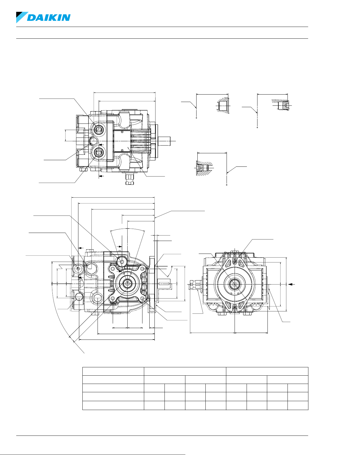
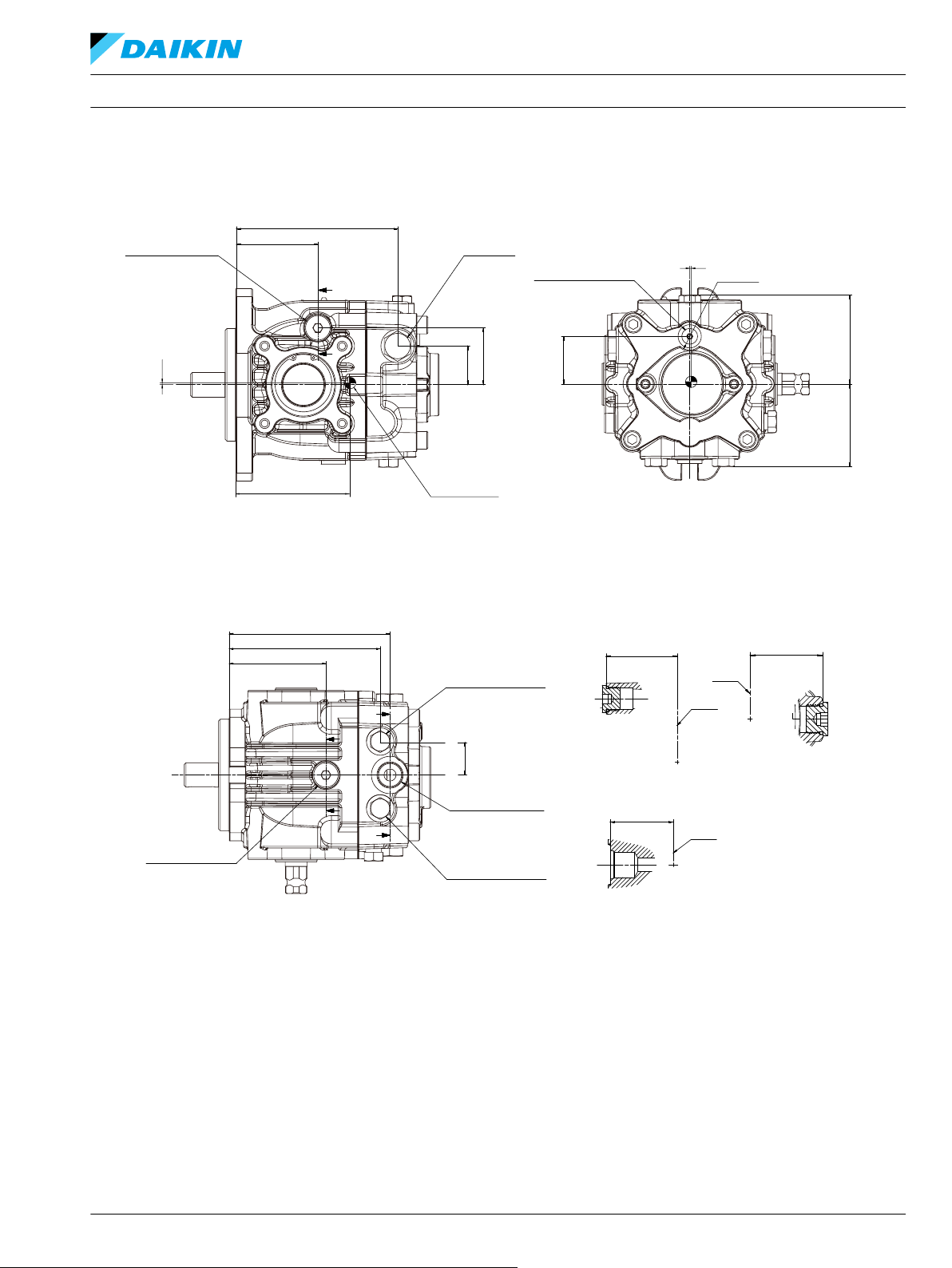
テクニカルインフォメーション DDC アキシャルピストンポンプ サイズ 20/24
外形図
補助 A パッド付き、チャージポンプなし、左トラニオン、取付フランジ SAE A 構成
32 BC152886484876ja-000309 • February 2022
入力軸回転
トラニオン位置 右 左 右 左
トラニオン回転
ポート A フロー
ポート B フロー
CW CCW
CW CCW CW CCW CW CCW CW CCW
Out In In Out In Out Out In
In Out Out In Out In In Out
Page 33
X
80.4 ±1.5
74.5 ±1.5
2x 53.2 ±0.2
2x 53.2 ±0.2
4x M10 x1.25
18 Full Thread Depth
180.5±1.2
149±1.2
77±0.8
134.5
Approximate
Center of Gravity
±1.2
35±0.8
35±0.834±0.8
51.5±0.8
Case Drain Port “L2”
Port ISO 11926-1 3/4-16
External Charge Supply Port “E”
From Filter
Or Charge Gage Port “M3”
Port ISO 11926-1 -9/16-18
High Pressure Relief Valve
D
D
System A Gage Port “MA”
Port ISO 11926-1 -9/16-18
Case Drain Port “L3”
Port ISO 11926-1 -3/4-16
E
E
E-E
D-D
2x 30.5±1.2
91
Shaft
Shaft
±0.8
68.5
±0.8
71
±0.8
2x 140.5
±1.2
System B Gage Port “MB”
Port ISO 11926-1 -9/16-18
P400132
(116)
(1)
(1)
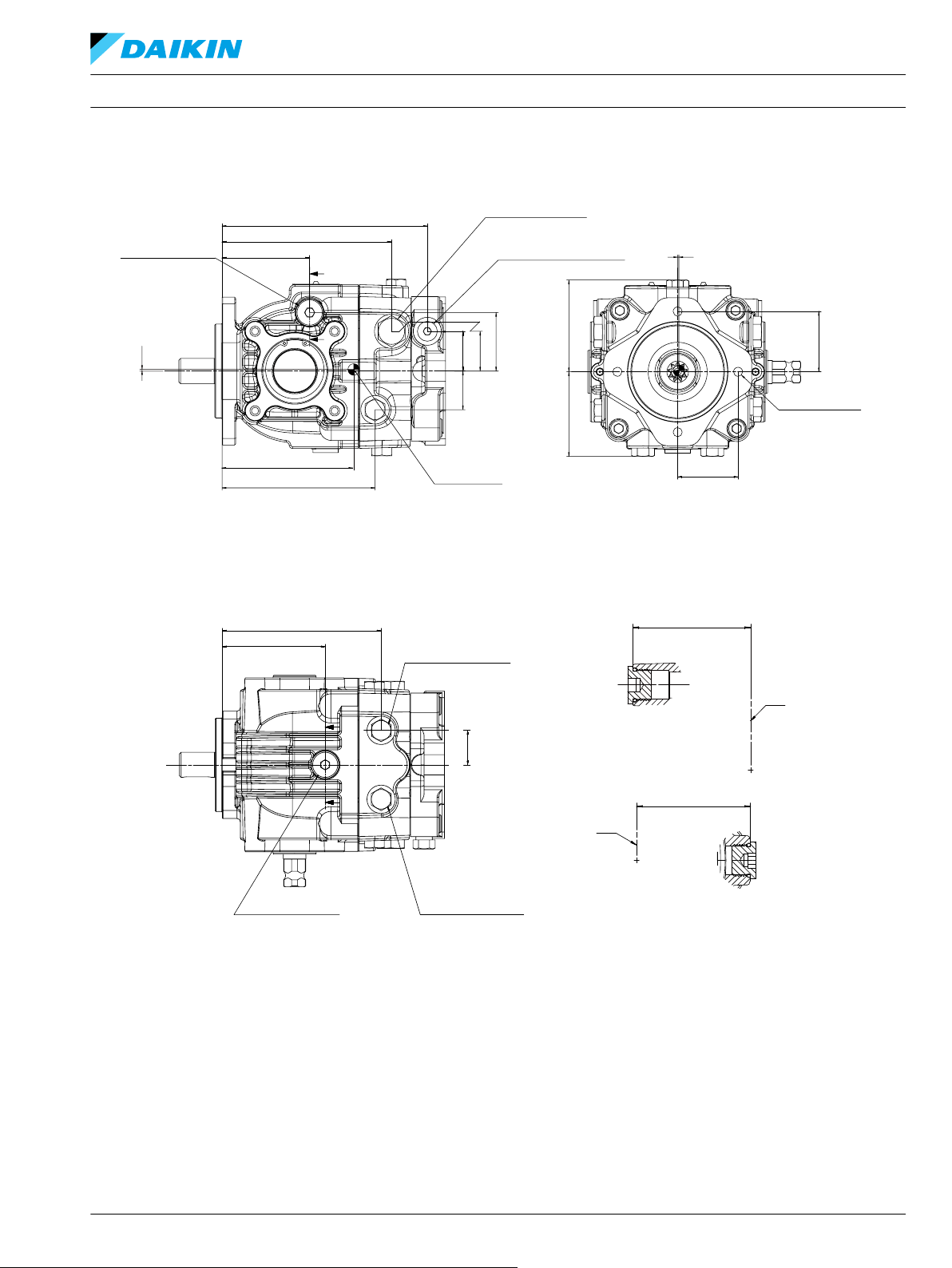
テクニカルインフォメーション DDC アキシャルピストンポンプ サイズ 20/24
外形図
BC152886484876ja-000309 • February 2022 33
Page 34

Paint
free
73 ±0.3
87 ±1.5
73 ±0.3
87 ±1.5
2x Ø14.3
+0.3
-0.1
Ø120
±1.5
108
±0.8
79.2
±1.5
193.5
±1.2
177.5±1.2
146±1.2
1.5±0.5
R0.75Max
Mounting Flange
Flange 101-2
Per ISO 3019-1 (SAE B)
74±0.8
60.94±0.8
B
B
C
C
9.7
0
-0.5
45°±5°
Ø101.6
0
-0.05
2x35
±0.8
2x35
±0.8
Paint Free
8x M8x 1.25
13 Full Thread
Depth
15
±1
131.5 ±1.2
2x 35±0.8
±0.82x 35
Bypass
Valve
Paint
Free
2x17
+0.06
-0.04
4x45°
±3°
34 ±0.8 35 ±0.8
51.5 ±0.8
35 ±0.831 ±0.8
CCW
CW
18°
Max Disp
18°
Max Disp
Case Drain Port “
L1
”
Port ISO 11926-1 -3/4-16
Port ISO 11926-1 -9/16-18
High Pressure Relief Valve
External Charge Supply Port “
E
”
From Filter
Or Charge Gage Port “
M3
”
X
C-C
B-B
Port ISO 11926-1-7/8-14
Port ISO 11926-1 -7/8-14
System Port "A"
System Port "B"
Charge Pressure
Relief Valve
Name Plate
Paint Free
A
A
2x 28 ±0.5
2x 137.5
±1.2
60.4
±0.8
150
±1.2
71
Shaft
Shaft
Shaft
±0.8
P400036
2x
A-A
73.6
±0.8
2x
150
±1.2
175.5 ±1.2
Paint
Free
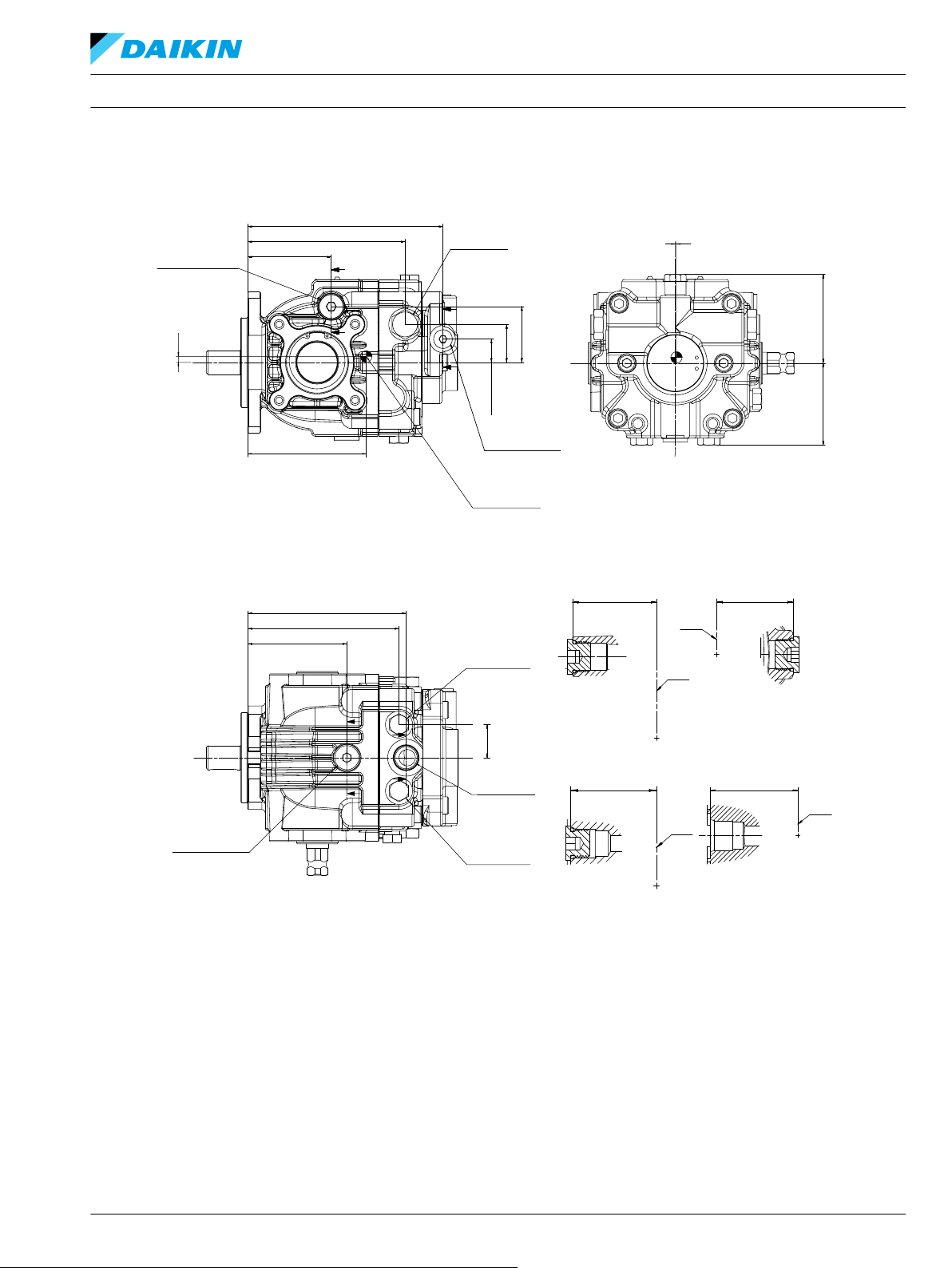
テクニカルインフォメーション DDC アキシャルピストンポンプ サイズ 20/24
外形図
補助 A パッド付き、チャージポンプなし、左トラニオン、取付フランジ SAE B 構成
34 BC152886484876ja-000309 • February 2022
Page 35

X
177.5
±1.2
131.5
±1.2
Case Drain Port “
L2
”
Port ISO
11926-1 -3/4-16
High Pressure Relief Valve
146
±1.2
74
±0.8
D
D
External Charge Supply Port “E”
From Filter
Or Charge Gage Port “M3”
Port ISO 11926-1 -9/16-18
51.5 ±0.8
35 ±0.8
35 ±0.834 ±0.8
2x 53.2 ±0.2
80.4 ±1.5
74.5 ±1.5
2x 53.2 ±0.2
4x M10 x1.25
18 Full Thread
Depth
Case Drain Port “L3”
PORT ISO 11926-1 -3/4-18
2x 137.5 ±1.2
88 ±0.8
System A Gage Port “MA”
PORT ISO 11926-1 -9/16-18
System B Gage Port “MB”
PORT ISO 11926-1 -9/16-18
2x 30.5±1.2
P400037
E
E
E-E
D-D
68.5
Shaft
Shaft
±0.8
71
±0.8
(111)
(2)
(1)
Approximate
Center of Gravity
テクニカルインフォメーション DDC アキシャルピストンポンプ サイズ 20/24
外形図
BC152886484876ja-000309 • February 2022 35
Page 36

Paint
Free
Paint
Free
53.2 ±0.3
53.2 ±0.3
65 ±1.5
65 ±1.5
Ø95
2x Ø11.1
±1.5
108
±0.8
79.2
±1.5
+0.3
-0.1
186.5±1.2
149±1.2
77 ±0.8
63.94±0.8
0.8
±0.5
R0.75 Max
CCW
CW
Case Drain Port “L1”
Port ISO
11926-1 3/4-16
High Pressure
Relief Valve
Mounting Flange
Flange 82-2
Per ISO 3019-1 (SAE A)
Bypass
Valve
Paint
Free
8x M8x 1.25
13 Full Thread
Depth
51.5 ±0.8
35 ±0.8
34 ±0.8
Ø82.55
0
-0.05
18°
Max Disp
18°
Max Disp
6.4
0
-0.5
12±1
134.5±1.2
B
B
2x35±0.82x35 ±0.8
45°
±5°
2x 35±0.82x 35±0.8
P400135
2x17
+0.06
-0.04
4x45°
±3°
X
A-A
B-B
System Port “A”
Name Plate
Paint Free
Charge Pressure
Relief Valve
A
Port ISO 11926-1 -7/8-14
2x 140.5
±1.2
153
Shaft
Shaft
±1.2
71
±0.8
2x 28 ±0.5
System Port “B”
Port ISO 11926-1 -7/8-14
P400135
73.6
2x
±0.8
テクニカルインフォメーション DDC アキシャルピストンポンプ サイズ 20/24
外形図
チャージポンプ付き、補助パッドなし、左トラニオン、取付フランジ SAE A 構成
36 BC152886484876ja-000309 • February 2022
Page 37

E-E
Shaft
D-D
Shaft
Shaft
65.6
±0.8
C-C
71
±0.8
68.5
±0.8
43.2 ±0.8
80.4
±1.5
74.5
±1.5
Charge Gage Port “M3”
Port ISO
R 12.5 Min
11926-1 -7/16-20
149±1.2
77±0.8
51.5 ±0.8
35
±0.8
Case Drain Port “L2”
Port ISO 11926-1 3/4-16
C
C
System A Gage Port “MA”
Port ISO 11926-1 -9/16-18
D
D
E
E
Charge Inlet Port “S”
Port ISO 11926-1 -7/8-14
Case Drain Port “L3”
Port ISO 11926-1 -3/4-16
2x 30.5 ±1.2
91
±0.8
2x 140.5
±1.2
149.5
±1.2
System B Gage Port “MB”
Port ISO 11926-1 -9/16-18
P400134
X
High Pressure
Relief Valve
(105)
(2)
(1)
Approximate
Center of Gravity
テクニカルインフォメーション DDC アキシャルピストンポンプ サイズ 20/24
外形図
BC152886484876ja-000309 • February 2022 37
Page 38

Ø 120
Port ISO 11926-1-7/8-14
Charge Pressure
Relief Valve
Name Plate
Paint Free
Shaft
System Port "B"
P400038
Port ISO 11926-1-7/8-14
System Port "A"
2x 28 ±0.5
2x 137.5
±1.2
150
±1.2
X
B-B
71
±0.8
Shaft
A-A
73.6
2x
±0.8
4x45°
±3°
2x17
+0.06
-0.04
Bypass
Valve
131.5 ±1.2
2x 35 ±0.8
±0.82x 35
15±1
Paint Free
8x M8x 1.25
13 Full Thread
Depth
2x35±0.8
2x35
±0.8
Ø101.6
0
-0.05
1.5±0.5
R0.75 Max
45°±5°
9.7
0
-0.5
CCW
CW
18°
Max Disp
18°
Max Disp
183.5 ±1.2
74 ±0.8
60.94 ±0.8
146 ±1.2
Case Drain Port “L1”
Port ISO 11926-1 3/4-16
Mounting Flange
Flange 101-2
Per ISO 3019-1 (SAE B)
High Pressure
Relief Valve
51.5±0.8
35 ±0.834±0.8
Paint
Free
Paint
Free
108 ±0.8 79.2 ±1.5
±1.5
2x Ø14.3
+0.3
-0.1
87 ±1.5
73 ±0.3 73 ±0.3
87 ±1.5
A
A
B
B
テクニカルインフォメーション DDC アキシャルピストンポンプ サイズ 20/24
外形図
チャージポンプ付き、補助パッドなし、左トラニオン、取付フランジ SAE B 構成
38 BC152886484876ja-000309 • February 2022
Page 39
P400039
X
146±1.2
74±0.8
Case Drain Port “L2”
Port ISO 11926-1 3/4-16
High Pressure
Relief Valve
35 ±0.8
74.5
±1.5
43.2 ±0.8
80.4 ±1.5
51.5±0.8
Charge Gage Port “M3”
Port ISO 11926-1 7/16-20
146.5 ±1.2
88 ±0.8
2x 137.5±1.2
System B Gage Port “MB”
Port ISO 11926-1 9/16-18
2x 30.5±1.2
Charge Inlet Port “S”
Port ISO 11926-1 7/8-14
System A Gage Port “MA”
Port ISO 11926-1 9/16-18
Case Drain Port “L3”
Port ISO 11926-1 3/4-16
C
C
E
D
D
Shaft
Shaft
Shaft
C-C
71
±0.8
E-E
68.5
±0.8
D-D
65.6
±0.8
(101)
(2)
(1)
Approximate
Center of Gravity
R 12.5 Min
テクニカルインフォメーション DDC アキシャルピストンポンプ サイズ 20/24
外形図
BC152886484876ja-000309 • February 2022 39
Page 40

Paint
Free
Paint
Free
53.2 ±0.353.2±0.3
65 ±1.5 65 ±1.5
Ø95
2x Ø11.1
±1.5
108
±0.8
79.2
±1.5
+0.3
-0.1
X
P400125
178.5±1.2
149 ±1.2
2x 139 ±1.2
System Port “B”
Port ISO 11926-1 7/8-14
Charge Gage Port “M3” Or
Implement return Port “E”
Charge Pressure
Relief Valve
Port ISO 11926-1 9/16-18
System Port “A”
Port ISO 11926-1 7/8-14
Name Plate
Paint Free
2x 30 ±0.5
B
B
A A
Case Drain Port “L1”
Port ISO
11926-1 3/4-16
Implement Return
Port “E” Or
Charge Gage Port “M3”
Port ISO
11926-1 9/16-18
High Pressure
Relief Valve
Bypass
Valve
51.5 ±0.8
35 ±0.8
32.5±0.832.5 ±0.8
2x17
+0.06
-0.04
4x45°
±3°
12±1
132.5±1.2
2x 35±0.82x 35±0.8
Paint
Free
8x M8x 1.25
13 Full Thread
Depth
R0.75 Max
Ø82.55
0
-0.05
2x35±0.82x35 ±0.8
45°±5°
193.5±1.2
178.5±1.2
145±1.8
77±0.8
63.94±0.8
0.8
±0.5
CCW
CW
18°
Max Disp
18°
Max Disp
6.4
0
-0.5
Mounting Flange
Flange 82-2
Per ISO 3019-1 (SAE A)
C
C
D
D
D-D
Shaft
71
±0.8
Shaft
C-C
60.9
±0.8
B-B
Shaft
73.6
2x
±0.8
Shaft
A-A
59.9
±0.8
テクニカルインフォメーション DDC アキシャルピストンポンプ サイズ 20/24
外形図
インプリメントポンプ付き、補助パッドなし、左トラニオン、取付フランジ SAE A 構成
40 BC152886484876ja-000309 • February 2022
Page 41
Shaft
Shaft
E-E
F-F
71
±0.8
60.9
±0.8
Shaft
Shaft
G-G
68.5
±0.8
H-H
65.6
±0.8
180
±1.2
145 ±1.2
77±0.8
21.5 ±0.8
35
±0.8
51.5 ±0.8
Case Drain Port “L2”
Port ISO 11926-1
3/4-16
Implement
Discharge Port “D”
Port ISO
11926-1 -9/16-18
High Pressure
Relief Valve
E
E
F
F
80.4 ±1.574.5 ±1.5
P400124
145.5 ±1.2
91±0.8
2x 139 ±1.2
System B Gage
Port “MB”
Port ISO 11926-1
9/16-18
2x 30.5±1.2
Charge Inlet
Port “S”
Port ISO 11926-1
7/8-14
System A Gage
Port “MA”
Port ISO 11926-1
9/16-18
Case Drain Port “L3”
Port ISO 11926-1
3/4-16
G
G
H
H
X
(109)
(5)
(1)
Approximate
Center of Gravity
テクニカルインフォメーション DDC アキシャルピストンポンプ サイズ 20/24
外形図
BC152886484876ja-000309 • February 2022 41
Page 42

System Port “A”
Name Plate
Paint Free
Charge Pressure
Relief Valve
Port ISO 11926-1 -7/8-14
System Port “B”
Port ISO 11926-1 -7/8-14
Port ISO 11926-1 -9/16-18
Charge Gage Port “M3” Or
Implement return Port “E”
51.5 ±0.8
35 ±0.8
32.5 ±0.832.5 ±0.8
C
C
D
D
190.5±1.2
175.5±1.2
142±1.8
74±0.8
60.94±0.8
CCW
CW
18°
Max Disp
18°
Max Disp
1.5
±0.5
9.7
0
-0.5
Mounting Flange
Flange 101-2
Per ISO 3019-1 (SAE B)
Paint
Free
8x M8x 1.25
13 Full Thread
Depth
R0.75 Max
Ø101.6
0
-0.05
2x35±0.82x35 ±0.8
45°±5°
15±1
129.5±1.2
2x 35±0.82x 35±0.8
Bypass
Valve
2x17
+0.06
-0.04
4x45°
±3°
Paint
Free
Paint
Free
73 ±0.3
73 ±0.3
87 ±1.5
87 ±1.5
Ø120
2x Ø14.3
±1.5
108
±0.8
79.2
±1.5
+0.3
-0.1
P400127
175.5 ±1.2
146±1.2
2x 136 ±1.2
2x 30±0.5
A
B
B
A
Case Drain Port “L1”
Port ISO 11926-1 3/4-16
High Pressure
Relief Valve
Implement Return Port “E”
Or Charge Gage Port “M3”
Port ISO
11926-1 -9/16-18
B-B
D-D
Shaft
Shaft
Shaft
Shaft
71
±0.8
C-C
A-A
60.9
±0.8
73.6
2x
±0.8
X
テクニカルインフォメーション DDC アキシャルピストンポンプ サイズ 20/24
外形図
インプリメントポンプ付き、補助パッドなし、左トラニオン、取付フランジ SAE B 構成
42 BC152886484876ja-000309 • February 2022
Page 43

80.4 ±1.574.5 ±1.5
P400126
177
±1.2
142 ±1.2
74±0.8
21.5 ±0.8
35
±0.8
51.5 ±0.8
Case Drain Port “L2”
Port ISO 11926-1
3/4-16
High Pressure
Relief Valve
E
F
F
E
X
Implement
Discharge Port “D”
Port ISO
11926-1 -9/16-18
142.5
±1.2
88 ±0.8
2x 136 ±1.2
Case Drain Port “L3”
Port ISO 11926-1
3/4-16
System B Gage
Port “MB”
Port ISO 11926-1
9/16-18
2x 30.5 ±1.2
G
G
H
H
Charge Inlet
Port “S”
Port ISO 11926-1
7/8-14
System A Gage
Port “MA”
Port ISO 11926-1
9/16-18
Shaft
E-E
71
±0.8
Shaft
Shaft
G-G
68.5
±0.8
H-H
65.6
±0.8
Shaft
F-F
60.9
±0.8
(104)
(5)
(1)
Approximate
Center of Gravity
テクニカルインフォメーション DDC アキシャルピストンポンプ サイズ 20/24
外形図
BC152886484876ja-000309 • February 2022 43
Page 44
Lever mounting surface
Paint free
Grease nipple
Paint free
±0.8
20 ±0.2
108 ±1.5
111 ±1.5
“GA”
±1.5
2x 21±0.5
“GB”
2x M10 x 1.5 THRU
P400749
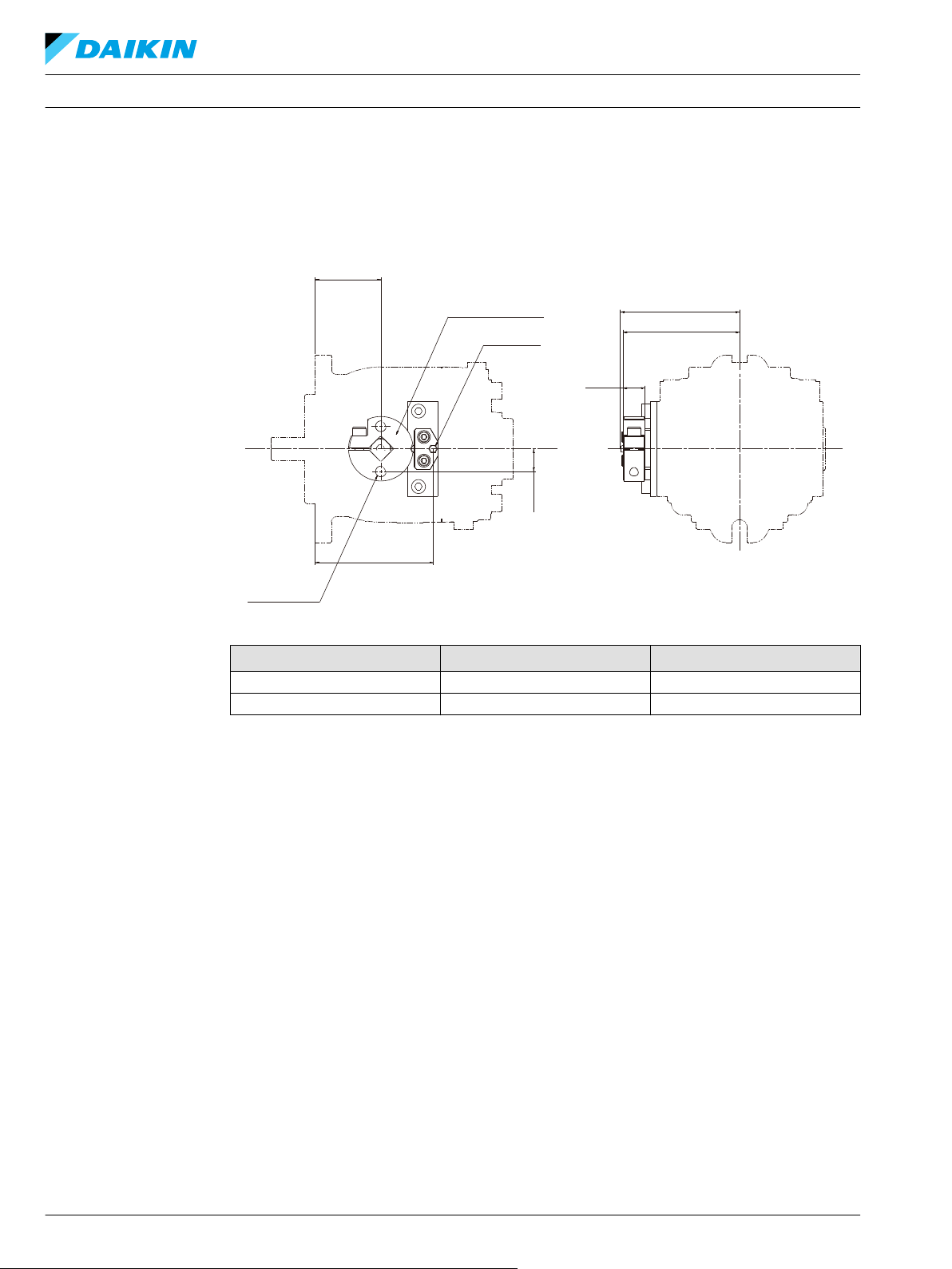
テクニカルインフォメーション DDC アキシャルピストンポンプ サイズ 20/24
外形図
オプション: デテント
取付フランジ "GA" 寸法 "GB" 寸法
SAE A 63.94 112.44
SAE B 60.94 109.44
44 BC152886484876ja-000309 • February 2022
Page 45
A-A
45°
2x Full R
A
A
Mating Coupling
Must Not Protrude
Beyond This Point
Mounting Flange
Flange 82-2
Per ISO 3019-1 (SAE A)
3
±0.3
+0.4
0
1.5
±0.4
±0.1
33
±0.3
5
±1
±0.3°
25.4
18.58
Ø22.2
+0.03
0
6.35
+0.05
0
Ø52
+0.03
0
P400128
Paint Free
33
±0.3
8±1
Paint Free
Mating Coupling
Must Not Protrude
Beyond This Point
Mounting Flange
Flange 101-2
Per ISO 3019-1 (SAE B)
2x FULL R
B
B
25.4
+0.4
0
3 ±0.3
45° ±0.3°
Ø22.2
+0.03
0
Ø52
+0.03
0
P400040
B-B
1.5
±0.4
±0.1
18.58
6.35
+0.05
0
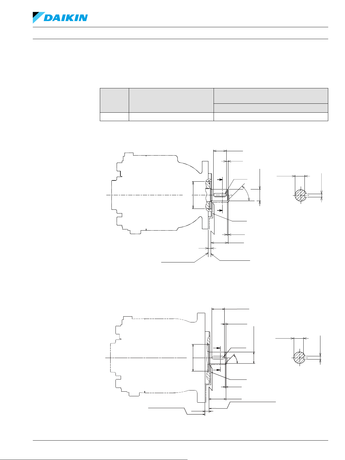
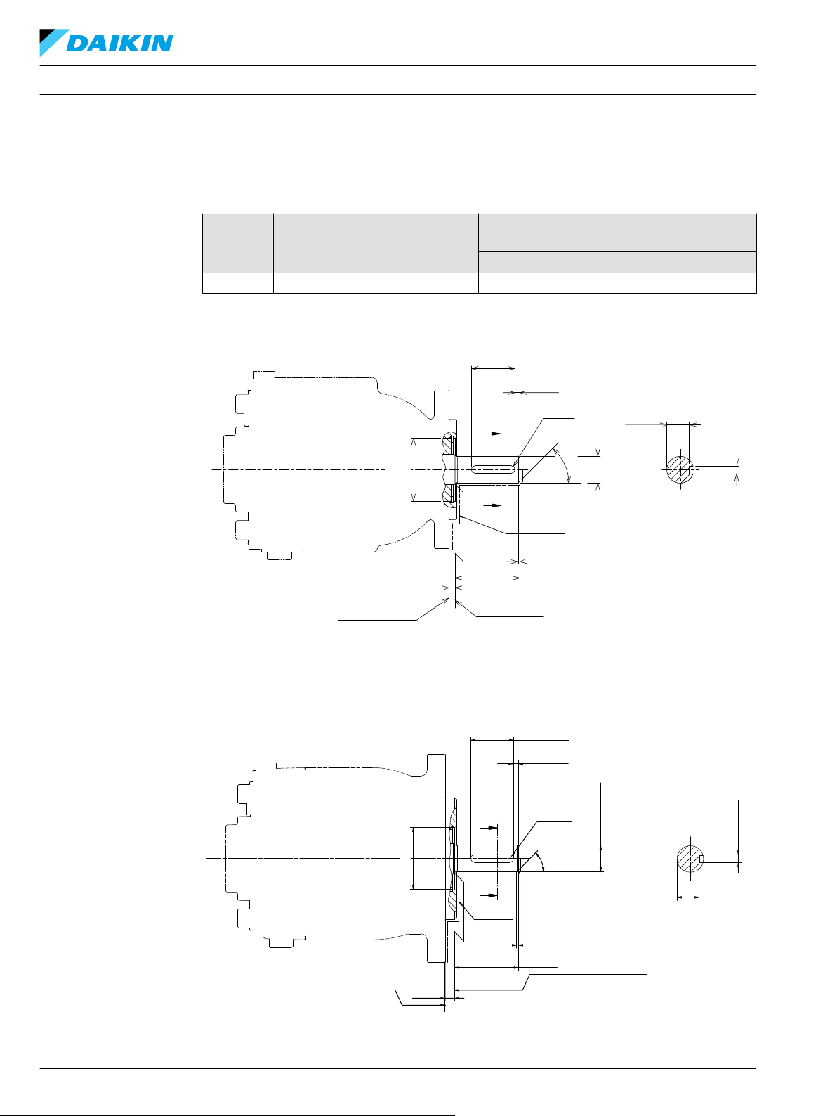
テクニカルインフォメーション
外形図
入力軸: AA, BA, DA
DDC アキシャルピストンポンプ サイズ 20/24
軸の形状と許容トルク
オプション シャフトデータ
AA, BA, DA
Ø 0.875 in、ストレートキー、33 mm
SAE A
トルク
N•m [lbf•in]
最大トルク
226 [2000]
SAE B
BC152886484876ja-000309 • February 2022 45
Page 46
A-A
45°
2x Full R
A
A
Mating Coupling
Must Not Protrude
Beyond This Point
Mounting Flange
Flange 82-2
Per ISO 3019-1 (SAE A)
36.1
4
5
1.5
53.5
18.58
Ø22.2
+0.03
0
6.35
+0.05
0
Ø52
+0.03
0
±0.5
±0.1
±1
±0.3
±0.3
±0.4
±0.3
P400129
Paint Free
53.5
±0.3
1.5
±0.4
8
±1
Paint Free
6.35
+0.05
0
18.58
±0.1
45° ±0.3°
2x FULL R
B
B
36.1
4
±0.3
±0.5
Mating Coupling
Must Not Protrude
Beyond This Point
Mounting Flange
Flange 101-2
Per ISO 3019-1 (SAE B)
P400041
Ø52
+0.03
0
Ø22.2
+0.03
0
B-B
テクニカルインフォメーション
外形図
入力軸: AB, BB, DB
DDC アキシャルピストンポンプ サイズ 20/24
軸の形状と許容トルク
オプショ シャフトデータ
AB, BB, DB
Ø 0.875 in, ストレートキー, 53mm
SAE A
トルク
N•m [lbf•in]
最大トルク
226 [2000]
SAE B
46 BC152886484876ja-000309 • February 2022
Page 47

Spline Data
Number of Teeth: 13
Pitch Fraction : 16/32
Pressure Angle : 30°
Pitch Dia : Ø20.638
Type of Fit : Fillet Root Side
Per : ANSI B92.1-1970 Class 5
Mating Coupling
Must Not Protrude
Beyond This Point
Mounting Flange
Flange 82-2
Per ISO 3019-1 (SAE A)
±0.5
±0.12
33
±0.3
5
±1
16.5
Ø18.7
±0.09
Ø21.72
Ø52
+0.03
0
P400130
Paint Free
Ø21.72
±0.09
Ø18.7
±0.12
Ø52
±0.03
0
Spline Data
Paint Free
Number of Teeth: 13
Pitch Fraction : 16/32
Pressure Angle : 30°
Pitch Ø : Ø20.638
Type of Fit : Fillet Root Side
Per : ANSI B92.1-1970 CLASS 5
33
±0.3
8
±1
16.5
±0.5
Mating Coupling
Must Not Protrude
Beyond This Point
Mounting Flange
Flange 101-2
Per ISO 3019-1 (SAE B)
P400042
テクニカルインフォメーション
外形図
入力軸: AC, BC, DC
DDC アキシャルピストンポンプ サイズ 20/24
軸の形状と許容トルク
オプション シャフトデータ
AC, BC, DC
13 歯 16/32 ピッチ ANSI B92.1-1970 クラ
ス 5
SAE A
トルク
N•m [lbf•in]
定格トルク 最大トルク
180 [1593] 236 [2088]
SAE B
BC152886484876ja-000309 • February 2022 47
Page 48
P400043
Auxiliary mounting pad
For mating flange 82-2
per ISO 3019-1 (SAE A)
Mating shaft must not
protrude beyond this poit
Mating shaft shoulder must not
protrude beyond this poit
R0.8 max
Ø88.62
+0.13
0
Ø82.6
+0.08
0
O-ring seal required
M10 x 1.5 (4x)
18 Full thread depth
Ref Ø82.22 ID x 2.62 cross section
1.96 ± 0.13
8.1 ± 0.25
14.4 min
Shaft clearance
32.85 min
Shaft clearance
Number of Teeth: 9
Pitch Fraction : 16/32
Pressure Angle : 30°
Pitch Ø : Ø14.288
Minor Ø : Ø12.89
Type of Fit : Fillet root side
Per : ANSI B92.1-1970 class 7
Spline data:
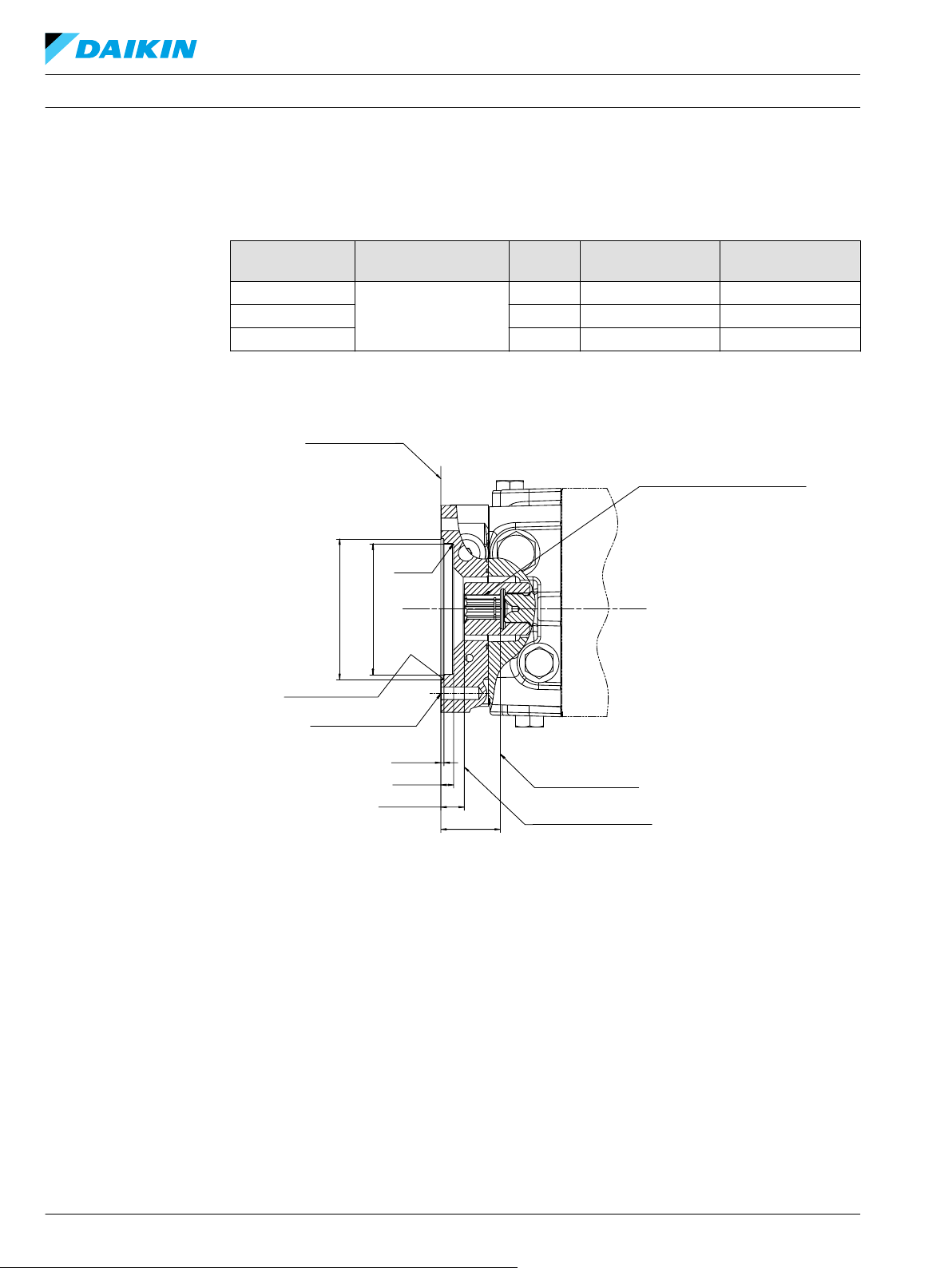
テクニカルインフォメーション
外形図
補助取付パッド
DDC アキシャルピストンポンプ サイズ 20/24
軸の形状と許容トルク
パッドサイズ フランジ スプライン
SAE A
SAE A スペシャル 11 歯
ISO 3019-1、フランジ 82-2
SAE A スペシャル 13 歯
1
23T 補助スプラインで制限
9 歯(オプション)
9 歯
有効スプライン長さ
mm [inch]
13.5 [0.53] 162 [1434]
13.5 [0.53] 194 [1717]
13.5 [0.53] 207 [1823]
最大トルク
N•m [lbf•in]
1
48 BC152886484876ja-000309 • February 2022
Page 49

P400044
Auxiliary mounting pad
For mating flange 82-2
per ISO 3019-1 (SAE A)
Mating shaft must not
protrude beyond this poit
Mating shaft shoulder must not
protrude beyond this poit
R0.8 max
Ø88.62
+0.13
0
Ø82.6
+0.08
0
O-ring seal required
Ref Ø82.22 ID x 2.62 cross section
1.96 ± 0.13
8.1 ± 0.25
14.4 min
Shaft clearance
37.85 min
Shaft clearance
Number of Teeth: 11
Pitch Fraction : 16/32
Pressure Angle : 30°
Pitch Ø : Ø17.463
Minor Ø : Ø15.940
Type of Fit : Fillet root side
Per : ANSI B92.1-1970 class 7
Spline data:
M10 x 1.5 (4x)
18 Full thread depth
Auxiliary mounting pad
For mating flange 82-2
per ISO 3019-1 (SAE A)
Mating shaft must not
protrude beyond this poit
Mating shaft shoulder must not
protrude beyond this poit
R0.8 max
Ø88.62
+0.13
0
Ø82.6
+0.08
0
P400300
O-ring seal required
Ref Ø82.22 ID x 2.62 cross section
1.96 ± 0.13
8.1 ± 0.25
14.4 min
Shaft clearance
37.85 min
Shaft clearance
Number of Teeth: 13
Pitch Fraction : 16/32
Pressure Angle : 30°
Pitch Ø : Ø20.638
Minor Ø : Ø19.110
Type of Fit : Fillet root side
Per : ANSI B92.1-1970 class 7
Spline data:
M10 x 1.5 (4x)
18 Full thread depth
テクニカルインフォメーション
外形図
DDC アキシャルピストンポンプ サイズ 20/24
11 歯(オプション)
13 歯(オプション)
BC152886484876ja-000309 • February 2022 49
Page 50

テクニカルインフォメーション
参考文献
文献
DDC アキシャルピストンポンプ サイズ 20/24
DDC ポンプや、その他ダンフォスコンポーネントの製品情報と仕様については、以下の文献を参照して
ください。
DDC ポンプの文献
•
油圧システム参考文献
•
•
•
•
•
アキシャルピストンポンプサービスマニュアル
DDC
Hydraulic Fluids and Lubricants Technical Information BC152886484524
Pressure and Speed Limits BC152886484313
Design Guidelines for Hydraulic Fluid Cleanliness BC152886482150
Experience with Biodegradable Hydraulic Fluids, Technical Information 520L465
Selection of Driveline Components BC157786484430
l AX152986482107
50 BC152886484876ja-000309 • February 2022
Page 51

本 社 〒
566-0044 大阪府摂津市西一津屋1-
1
TEL: 06-6349-7264 FAX: 06-6349-6789
西日本営業
〒
532-0004 大阪府大阪市淀川区西宮原1-5-28 新大
阪テラサキ第3ビル6F
TEL: 06-6395-6090 FAX: 06-6395-8585
東日本営業 〒
101-0044 東京都千代田区鍛冶町
2-7-1
神
田IKビル8F
主な取扱製品:
•
油圧ポンプ
•
油圧モータ
•
ギアポンプ
•
ギアモータ
•
PLUS+1® ソフトウェア
•
コントローラ
•
ディスプレイ
•
ジョイスティック
•
リモートコントロール
•
位置制御およびセンサ
•
PVG 比例弁
•
油圧ステアリング
•
e ステアリング
•
オービタルモータ
•
テレマティクス
ダイキン・ザウアーダンフォスは、世界各地に製造拠点と販売拠点を展開し、世界の車両市
場にシステムソリューションを提供する総合油圧機器メーカーのダンフォスグループととも
に、車両用油圧 システムの専門メーカーとして皆様のベストパートナーを目指しています。
閉回路用ポンプ・モータ、 開回路用ポンプ、 オービタルモータ、 バルブ、 ステアリングコ
ンポーネント、 電子油圧制御機器など、 豊富で広範囲にわたる製品群とシステムを取り揃
え、 農業・建設・ 物流・道路・芝刈・林業・オフハイウエイ環境等、 様々な分野で幅広く使用さ
れています。
また豊富な販売代理店網および認定サービスセンターのネットワークを通して、グローバル
なサービスを提供できる国際企業として高い評価をいただいています。
ダイキン・ザウアーダンフォスは、カタログ・資料およびその他の印刷物あるいは電子資料に生じ得る誤りに対して責任を負うものではありません。また弊社は予告なく製品仕様を変更する権利
を有します。この変更は、すでに合意された仕様の変更を必要とするものでない限り、すでに発注された製品にも適用されます。本資料のすべての商標は該当各社が所有するものです。Danfoss、
Danfoss ロゴタイプ、S-icon、PLUS+1®はダンフォスグループの商標です。Daikin、Daikin ロゴはダイキングループの商標です。無断転載を禁じます。
BC152886484876ja-000309 • February 2022 www.danfoss.com
©
Danfoss A/S, 2021
 Loading...