

Page 1
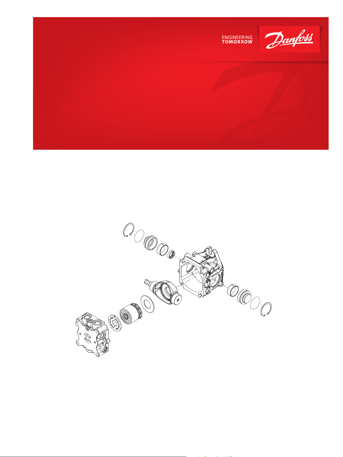
Parts Manual
DDC Axial Piston Pumps
Size 20/24
www.danfoss.com
Page 2

Parts Manual
DDC20/24
Revision history Table of revisions
Date Changed Rev
March 2022 Added AN (Detent), Changed document number from 'AX00000134' to 'AX152886483058' 0503
June 2019 Added DDC24 0401
July 2017 Updated to Engineering Tomorrow design 0302
2 | © Danfoss | March 2022 AX152886483058en-000503
Page 3

Parts Manual
DDC20/24
Contents
General information
Service parts identification........................................................................................................................................................... 4
Nameplate...........................................................................................................................................................................................4
Date code............................................................................................................................................................................................ 5
About service bulletins...................................................................................................................................................................5
Procedure to identify a part..........................................................................................................................................................5
Regional part numbers............................................................................................................................................................. 5
Adobe Acrobat 2-page viewing..................................................................................................................................................6
Order code.......................................................................................................................................................................................... 7
Displacement, valve plate, control arm
Displacement.....................................................................................................................................................................................8
Valve Plate...........................................................................................................................................................................................9
Control Arm........................................................................................................................................................................................9
Neutral assist mechanism
AN (Detent).......................................................................................................................................................................................10
Shaft
Shaft AA-BC......................................................................................................................................................................................12
Shaft DA-DD.....................................................................................................................................................................................14
Loop flushing
Loop Flushing 2-3 and D............................................................................................................................................................. 16
End cap
End Cap AAC9................................................................................................................................................................................. 18
End Cap AAN1.................................................................................................................................................................................20
End cap AAN3..................................................................................................................................................................................22
End cap AAN9..................................................................................................................................................................................24
End cap ABN1..................................................................................................................................................................................26
End cap ABN3..................................................................................................................................................................................28
End cap ABN9..................................................................................................................................................................................30
End cap ACA0 and ACD0.............................................................................................................................................................32
End cap BCF0 and BCFN.............................................................................................................................................................. 34
Charge pump
Charge Pump 3-5 and B-C...........................................................................................................................................................36
Charge Pump D...............................................................................................................................................................................38
Charge Pump E, F and G..............................................................................................................................................................40
Charge pressure relief
Charge Pressure Relief 5-18........................................................................................................................................................42
System protection
System Pressure Protection, 00N, 14A-30N..........................................................................................................................44
System Pressure Protection 32A-34N, 00N, 14A-25N....................................................................................................... 46
System Pressure Protection 28A-34N.....................................................................................................................................48
Input flange
Input Flange A-E.............................................................................................................................................................................50
Input Flange F-L..............................................................................................................................................................................52
Overhaul seal kit
DDC20 Overhaul Seal Kit.............................................................................................................................................................54
©
Danfoss | March 2022 AX152886483058en-000503 | 3
Page 4
MADE IN JAPAN.
Serial No.
J110912345
Model Code
Model No./Ident No.
11083308
DDC 20 A L LB RSA
NN A N 3 AB ACD0 C
07 25 A NNN NNN
Parts Manual
DDC20/24
General information
Service parts identification
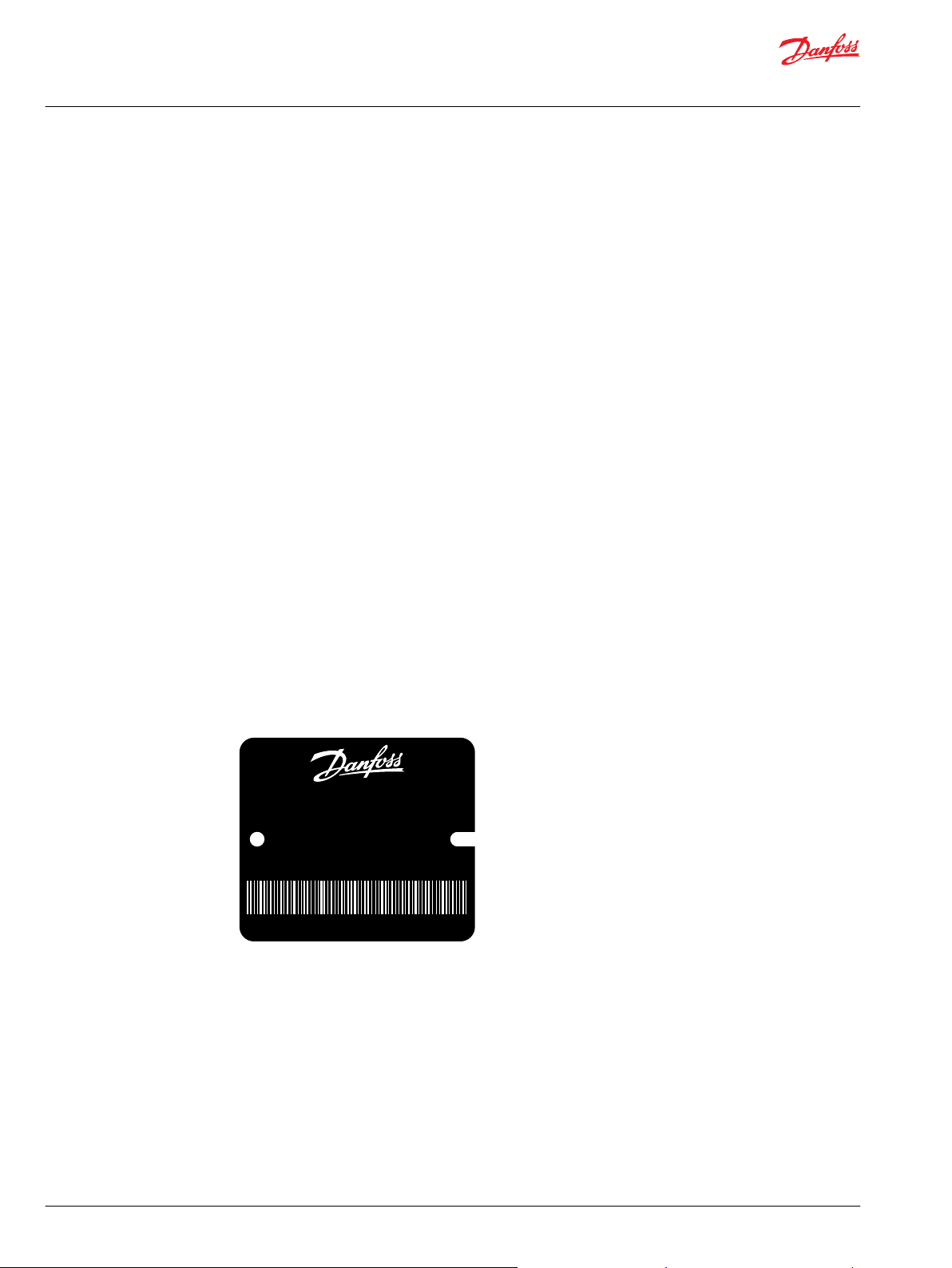
Nameplate
The following information and procedure is used to identify the module group, item number,
manufacture date, part number, and part name of the parts included in the .
The parts listed include all parts which may be used when performing either “Minor Repairs”, “Major
Repairs” or “Conversions” on the DDC20.
Each unit will have a nameplate affixed to the housing. The nameplate of the DDC20 will include the
following information:
Model code
The Danfoss model code completely defines the specific unit and must be used when ordering parts to
service this product.
Model/material number
The Danfoss model number (also known as material number) is used by the factory in manufacturing. On
repeat orders, a complete unit can be ordered by the model number.
Serial number
The Danfoss serial number is used to identify the manufacture date and the unit sequence in the build.
The serial number is also used to identify the units warranty time period.
The letter code indicates the location of original manufacture (assembly).
The first number (2 digits) indicates the year of manufacture. The second number (2 digits) indicates the
calendar week of manufacture.
The third number (5 digits) is a sequential number used to identify a specific unit.
4 | © Danfoss | March 2022 AX152886483058en-000503
Page 5
Parts Manual
DDC20/24
General information
Date code
About service bulletins
The date code is defined as the year and week of manufacture. The same item number may list more than
one part number. This indicates that there is more than one configuration for that item number. You will
see that there are different date codes for the different part numbers. Find the date code of your unit
from the nameplate to determine which service part number you need to order.
Example: The service part desired is item G30
Order Code Item Date Begin Date End Part Number Part Name Qty. per
80 G30 89-17 8000243 End cap gasket 1
G30 89-16 8000151 End cap gasket
(SB-1995-006)
Model/Kit
1
All units using this order code with a date code prior to 89-17 must use part number “8000151.” All units
with a date code of 89-17 and newer must use part number “8000243.”
A Service Bulletin Number (SB-_ _ _ _ - _ _ _) may follow the “Part Name” of the part you desire. You must
read that Service Bulletin prior to ordering that part. The information contained in these Service Bulletins,
as of the print date of this bulletin, are included at the end of this manual. Service Bulletins contain more
detailed information such as interchangeability, what additional parts are involved, etc. It is suggested
that you add additional Service Bulletins to this manual as you receive them.
Procedure to identify a part
The modular design of this product results in a simplified service parts list and part number identification
procedure.
The same item numbers are used for same part names on all units within a product type. A part number
that has another number following it in parentheses is done to make this a world wide manual.
Regional part numbers
Some part numbers are region specific and should be ordered accordingly.
As an example, the part number (example: 314583 (9008000-0118) will be used. The first number is sold
in Germany. The number in parentheses is sold in the United States. Customers would order
9008000-0118 if ordering the part in the United States.
©
Danfoss | March 2022 AX152886483058en-000503 | 5
Page 6
Parts Manual
DDC20/24
General information
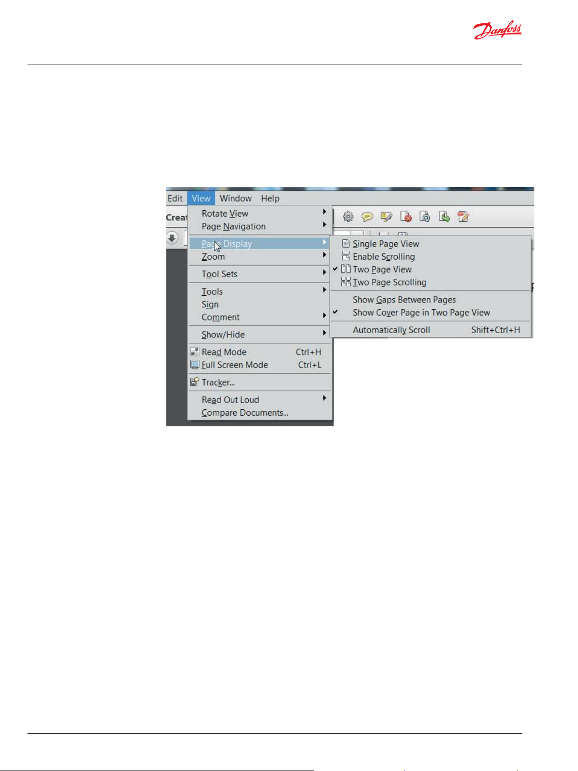
Adobe Acrobat 2-page viewing
While viewing manual in Adobe Acrobat, the following settings need to be applied to ensure proper
page display.
1. Select “View” → “Page Display” → “Two Page View”
2. Select “View” → “Page Display” → “Show Cover Page in Two Page View”
6 | © Danfoss | March 2022 AX152886483058en-000503
Page 7
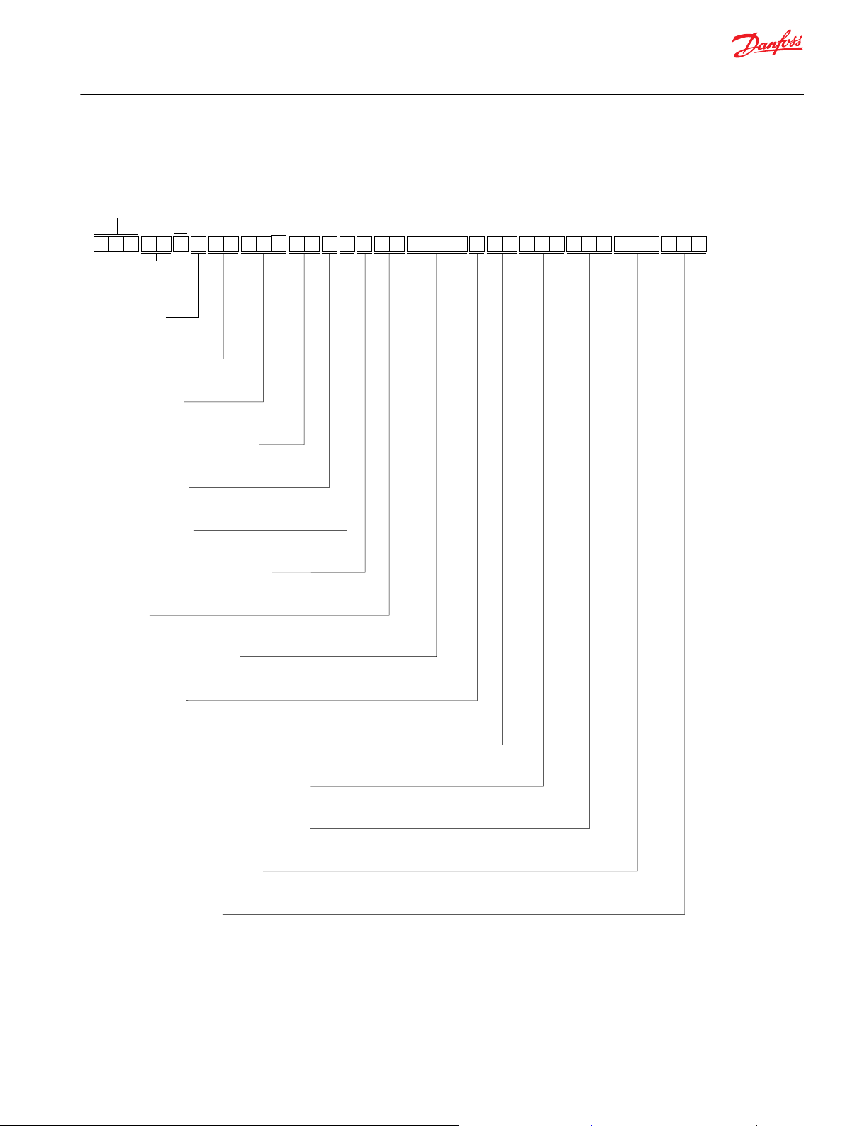
DDC
2
0
L
B
R
S
N
N 3
A
N
A
A B
7
5 AC D
A
5
2
Frame
Size
Valve plate
Neutral assist mechanism
Control arm
Bypass valve
Loop flushing
Charge pump displacement
Shaft
End cap/auxiliary pad
C E G M
P108 588E
H L
2
NK F J
C 0
0
S
NA NXNN N N
ZP
Input flange
Charge pressure relief setting
Paint and nametag
System pressure protection, port A
System pressure protection, port B
Special hardware features
Series
A
Rotation
L
Product
Version
Parts Manual
DDC20/24
General information
Order code
©
Danfoss | March 2022 AX152886483058en-000503 | 7
Page 8
*E320
E225
E200
*E220
E325
*E210
E300
E100
E100
E105
C010
*E320
E325
E300
E200
E225
*E220
*E210
A100
E105
C010
A100
E101 822E
(LSA)
(RSA)
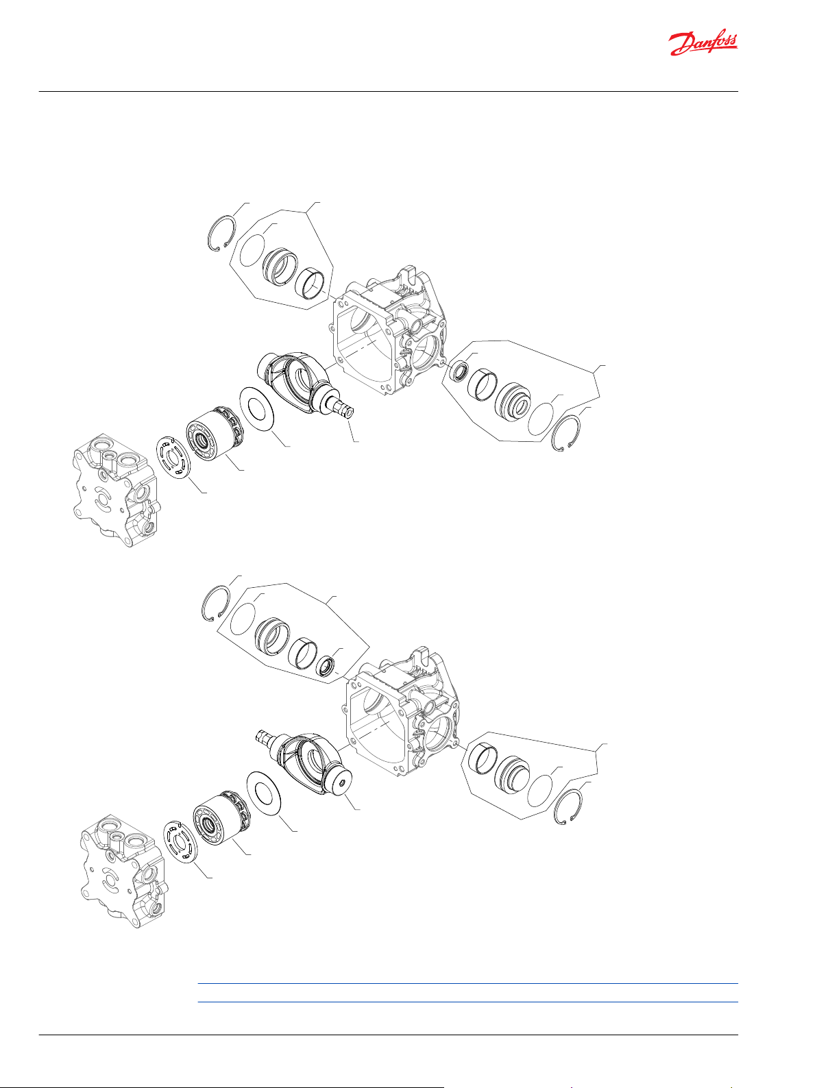
Parts Manual
DDC20/24
Displacement, valve plate, control arm
Displacement
* Included in overhaul seal kit Q210
Generic housing used to show part location only.
8 | © Danfoss | March 2022 AX152886483058en-000503
Page 9
Parts Manual
DDC20/24
Displacement, valve plate, control arm
Order code: 20 parts
Item Date Begin Date End Part Number Part Name Qty. per
A100 11-34 11051773 Cylinder block kit (DDC20 only) 1
A100 19-25 11229017 Cylinder block kit (DDC24 only) 1
Valve Plate
Order code: LA parts
Item Date Begin Date End Part Number Part Name Qty. per
C010 11-34 11065497 Valve plate, CCW, low control moment 1
LB parts
C010 11-34 11087147 Valve plate, CCW, high neutral seeking 1
Model/Kit
Model/Kit
RA parts
C010 11-34 11050370 Valve plate, CW, low control moment 1
RB parts
C010 11-34 11091396 Valve plate, CW, high neutral seeking 1
Control Arm
Order code: LSA and RSA common parts
Item Date Begin Date End Part Number Part Name Qty. per
E100 11-34 11230539 Swashplate, axial offset 1
E105 11-34 11050101 Thrust plate 1
E210 11-34 11050327 Lip seal 1
E220 11-34 9004104-1360 O-ring 1
E225 11-34 FBE056 Retaining ring 1
E320 11-34 9004104-1360 O-ring 1
E325 11-34 FBE056 Retaining ring 1
Model/Kit
LSA parts
E200 11-34 11083526 Journal bearing carrier assembly 1
E300 11-34 11083525 Journal bearing carrier assembly 1
RSA parts
E200 11-34 11083525 Journal bearing carrier assembly 1
E300 11-34 11083526 Journal bearing carrier assembly 1
©
Danfoss | March 2022 AX152886483058en-000503 | 9
Page 10
G150
G210
G330
G320
G230
G220
G300
G310
G100
P400750
G200
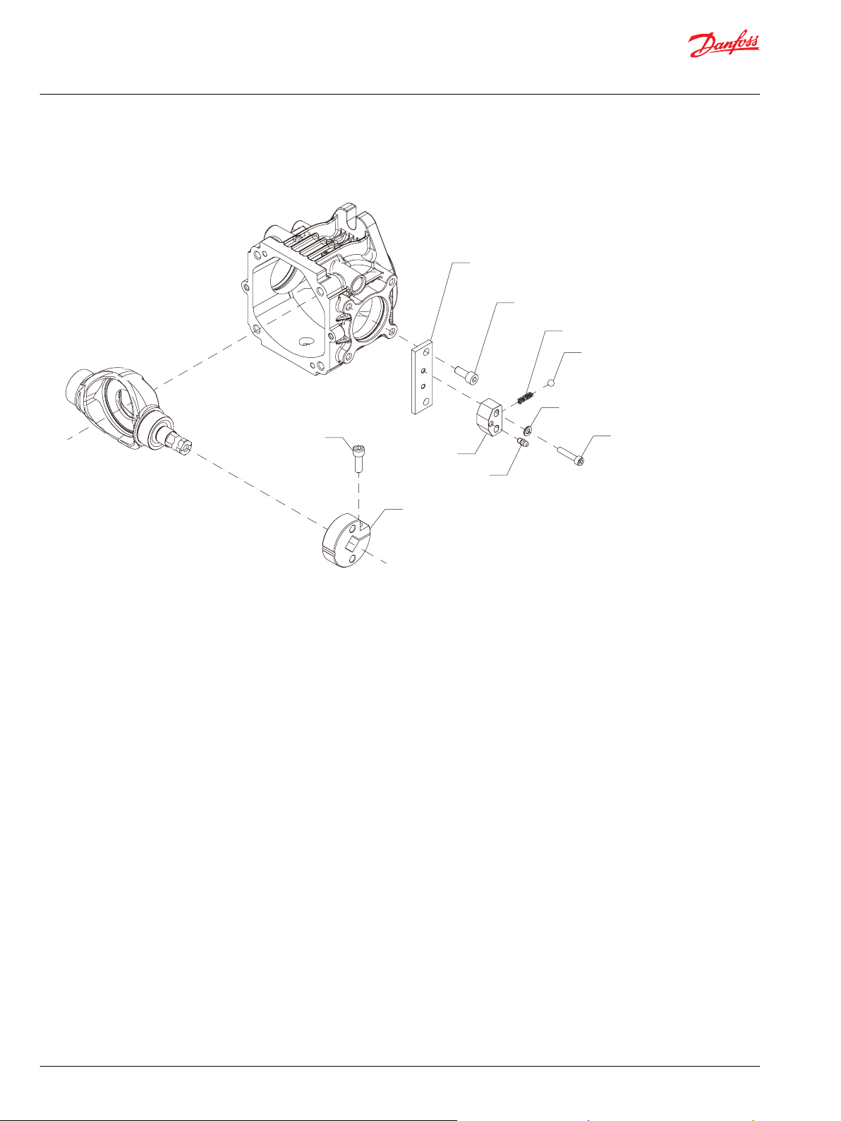
Parts Manual
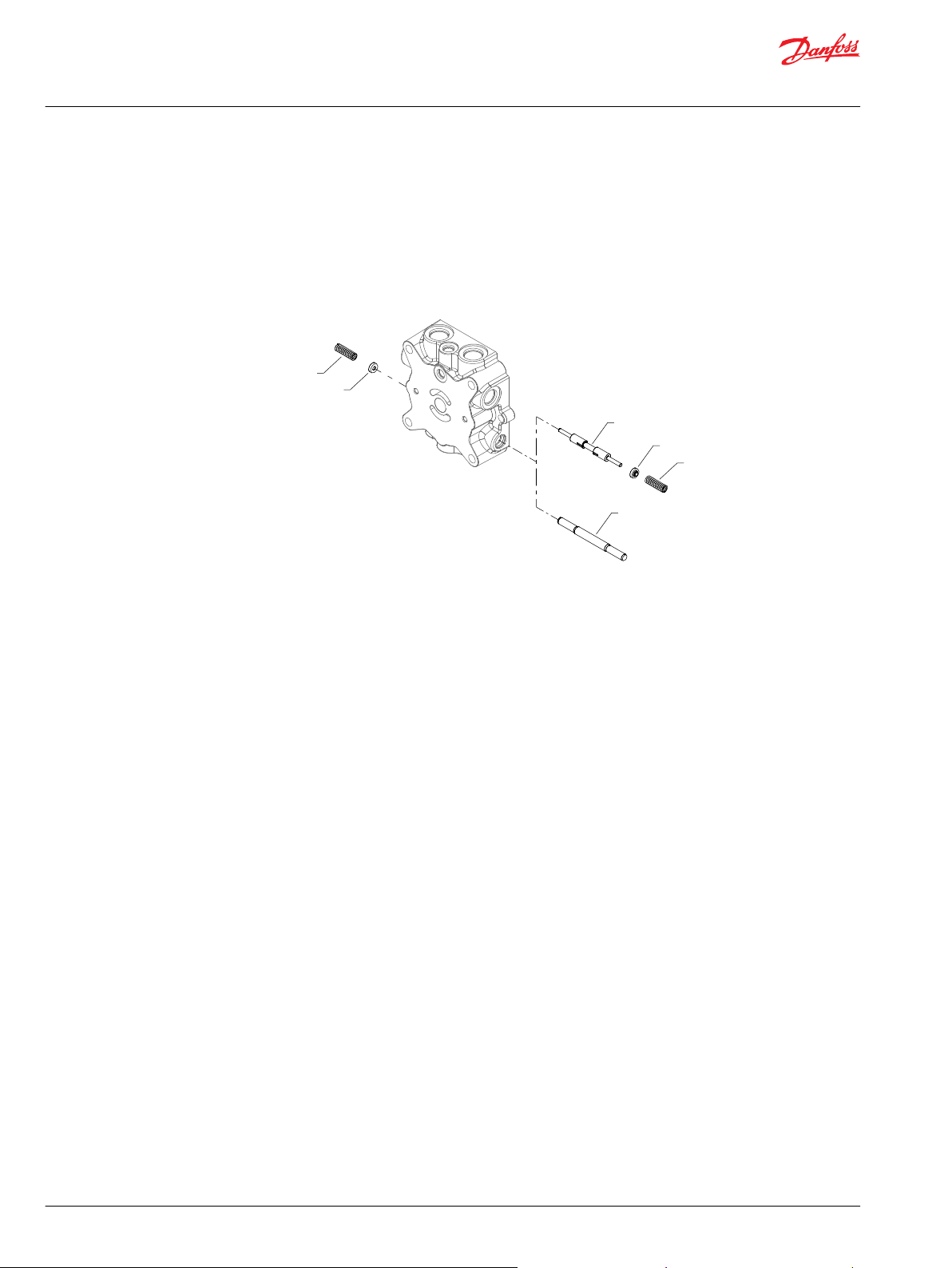
DDC20/24
Neutral assist mechanism
AN (Detent)
10 | © Danfoss | March 2022 AX152886483058en-000503
Page 11
Parts Manual
DDC20/24
Neutral assist mechanism
Order code: AN (Detent)
Item Date Begin Date End Part Number Part Name Qty. per
G100 22-08 11247397 Lever-Detent, DDC 1
G150 22-08 11247398 Plate-Detent, DDC 1
G200 22-08 AAN0802501 Screw-Soc HD, M8x25 JIS B1176 1
G210 22-08 AAM0802001 Screw-Soc HD, M8x20 JIS B1176 2
G220 22-08 AAM0603001 Screw-Soc HD, M6x30 JIS B1176 2
G230 22-08 11050795 Spring Washer 2
G300 22-08 1040323 Spring Case 1
G310 22-08 B1575A-M6 Grease Nipple 1
G320 22-08 HKWS5 Steel Ball 5/16 JIS B1501 1
G330 22-08 1040324 Spring 1
Model/Kit
©
Danfoss | March 2022 AX152886483058en-000503 | 11
Page 12

F105
F110
F115
*F120
F125
F100
F100
F100
F100
F100
F205
F100
(BC)
(BB)
(BA)
(AC)
(AB)
(AA)
Parts Manual
DDC20/24
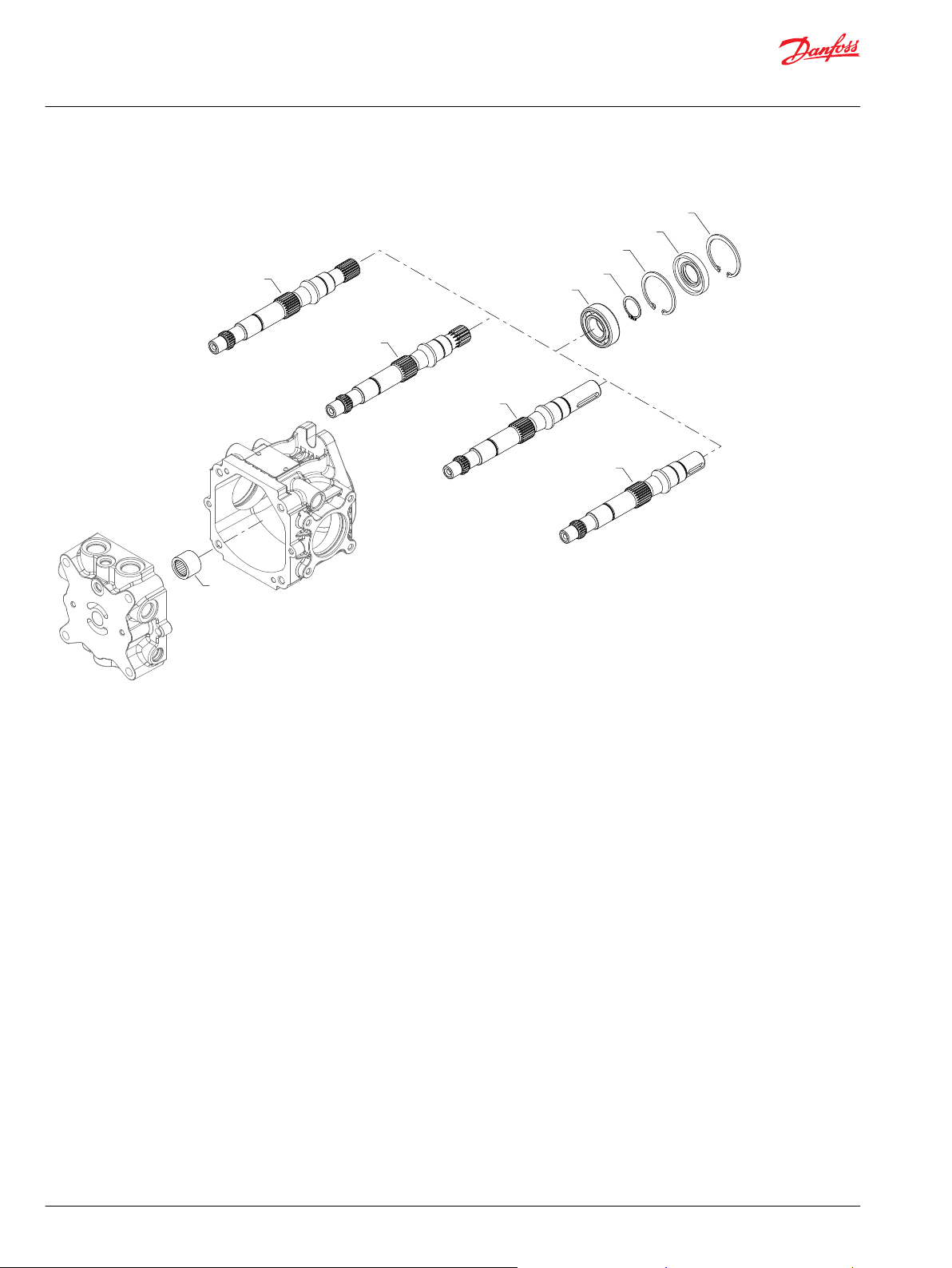
Shaft
Shaft AA-BC
* Included in overhaul seal kit Q210
12 | © Danfoss | March 2022 AX152886483058en-000503
Page 13
Parts Manual
DDC20/24
Shaft
Order code: all common parts
Item Date Begin Date End Part Number Part Name Qty. per
F105 11-34
F110 11-34
F115 11-34
F120 11-34
F125 11-34
F205 11-34
1
Date Begin for order code BB is 14-45
1
1
1
1
1
1
SP0984 Ball bearing 1
FBD025 Retaining ring 1
FBE052 Retaining ring 1
11082827 Lip seal 1
FBE052 Retaining ring 1
11050329 Needle bearing 1
AA parts
F100 11-34 11094869 Shaft, straight key (33mm) 1
AB parts
F100 11-34 11075897 Shaft, straight key (53mm) 1
Model/Kit
AC parts
F100 11-34 11094870 Shaft, 13 tooth spline 1
BA parts
F100 11-34 11095057 Shaft, straight key (33mm), auxiliary drive 1
BB parts
F100 14-45 11150105 Shaft, straight key (53mm), auxiliary drive 1
BC
F100 11-34 11096321 Shaft, 13 tooth spline, auxiliary drive 1
©
Danfoss | March 2022 AX152886483058en-000503 | 13
Page 14
F105
F110
F115
*F120
F125
F100
F205
F100
F100
F100
E103 680
(DD)
(DC)
(DB)
(DA)
Parts Manual
DDC20/24
Shaft
Shaft DA-DD
* Included in overhaul seal kit Q210
14 | © Danfoss | March 2022 AX152886483058en-000503
Page 15
Parts Manual
DDC20/24
Shaft
Order code: all common parts
Item Date Begin Date End Part Number Part Name Qty. per
F105 14-45 SP0984 Ball bearing 1
F110 14-45 FBD025 Retaining ring 1
F115 14-45 FBE052 Retaining ring 1
F120 14-45 11082827 Lip seal 1
F125 14-45 FBE052 Retaining ring 1
F205 14-45 11050329 Needle bearing 1
DA parts
F100 14-45 11154184 Shaft, straight key (33mm), auxiliary drive 1
DB parts
F100 14-45 11154183 Shaft, straight key (53mm), auxiliary drive 1
Model/Kit
DC parts
F100 14-45 11152845 Shaft, 13 tooth, auxiliary drive 1
DD parts
F100 14-45 11152846 Shaft, 20 tooth, auxiliary drive 1
©
Danfoss | March 2022 AX152886483058en-000503 | 15
Page 16
E103 250E
H150
H200
H100
H100
H150
H200
(2 & 3)
(D)
Parts Manual
DDC20/24
Loop flushing
Loop Flushing 2-3 and D
* Included in overhaul seal kit Q210
16 | © Danfoss | March 2022 AX152886483058en-000503
Page 17

Parts Manual
DDC20/24
Loop flushing
Order code: 2 parts
Item Date Begin Date End Part Number Part Name Qty. per
H100 11-34 11098179 Spool 1
H150 11-34 11097840 Spring 2
H200 11-34 1745296 Spring guide 2
3 parts
H100 15-36 11120528 Spool 1
H150 15-36 11097840 Spring 2
H200 15-36 1745296 Spring guide 2
D parts
H100 11-34 11098213 Spool, defeated 1
Model/Kit
©
Danfoss | March 2022 AX152886483058en-000503 | 17
Page 18

*J095
J110
J105
J200
J210
J100
J320
J230
*J400
*J410
J540
J450
J600
*M130
*M110
*M120
J520
J510
M100
J550
J538
J630
J610
J535
J140
*QJ020
*QJ020
J150
J220
*QJ040
Parts Manual
DDC20/24
End cap
End Cap AAC9
* Included in overhaul seal kit Q210
18 | © Danfoss | March 2022 AX152886483058en-000503
Page 19

Parts Manual
DDC20/24
End cap
Order code: AAC9 parts
Item Date Begin Date End Part Number Part Name Qty. per
J095 11-34 11082808 Gasket 1
J100 11-34 11100320 End cap 1
J105 11-34 9004700-1910 Slotted pin 1
J110 11-34 9004800-2506 Pin 2
J140 11-34 11080925 Plug assembly 1
J150 11-34 11080925 Plug assembly 1
J200 11-34 9005100-5600 Plug assembly 1
J210 11-34 9005100-5600 Plug assembly 1
J220 11-34 9005100-5600 Plug assembly 1
J230 11-34 9005100-5600 Plug assembly 1
J320 11-34 1030155-SA Plug assembly 1
J400 11-34 9004105-0160 O-ring 3
J410 11-34 9004104-0320 O-ring 1
J450 11-34 11098094 Adapter, A pad 1
J510 11-34 9005110-5600 Plug assembly 1
J520 11-34 9005110-5600 Plug assembly 1
J535 11-34 FBE013 Retaining ring 1
J538 11-34 11102274 Coupling assembly, 9 tooth 1
J540 11-34 9004800-2506 Pin 2
J550 11-34 AAM1008001 Screw 4
J600 11-34 9004100-1520 O-ring 1
J610 11-34 1040577 Flange cover 1
J630 11-34 AAM1002001 Screw 2
M100 11-34 11083527 Bypass valve assembly 1
M110 11-34 11106929 O-ring 1
M120 11-34 11076700 Back up ring 1
M130 11-34 KP4F007 O-ring 1
QJ020 11-34 9004201-5000 O-ring 2
QJ040 11-34 9004201-3100 O-ring 1
Model/Kit
©
Danfoss | March 2022 AX152886483058en-000503 | 19
Page 20

J110
J105
J220
J200
J210
J100
J230
*J400
*J410
J540
J450
J600
*M130
*M110
*M120
J520
J510
M100
J550
J538
J630
J610
J140
*QJ020
*QJ020
J150
*J095
J320
*QJ040
Parts Manual
DDC20/24
End cap
End Cap AAN1
* Included in overhaul seal kit Q210
20 | © Danfoss | March 2022 AX152886483058en-000503
Page 21

Parts Manual
DDC20/24
End cap
Item Date Begin Date End Part Number Part Name Qty. per
J095 11-34 11082808 Gasket 1
J100 11-34 11098093 End cap 1
J105 11-34 9004700-1910 Slotted pin 1
J110 11-34 9004800-2506 Pin 2
J140 11-34 11080925 Plug assembly 1
J150 11-34 11080925 Plug assembly 1
J200 11-34 9005100-5600 Plug assembly 1
J210 11-34 9005100-5600 Plug assembly 1
J220 11-34 9005100-5600 Plug assembly 1
J230 11-34 9005100-5600 Plug assembly 1
J320 11-34 1030155-SA Plug assembly 1
J400 11-34 9004105-0160 O-ring 3
J410 11-34 9004104-0320 O-ring 1
J450 11-34 11098094 Adapter, A pad 1
J510 11-34 9005110-5600 Plug assembly 1
J520 11-34 9005110-5600 Plug assembly 1
J538 11-34 11096305 Coupling, 11 tooth 1
J540 11-34 9004800-2506 Pin 2
J550 11-34 AAM1008001 Screw 4
J600 11-34 9004100-1520 O-ring 1
J610 11-34 1040577 Flange cover 1
J630 11-34 AAM1002001 Screw 2
M100 11-34 11083527 Bypass valve assembly 1
M110 11-34 11106929 O-ring 1
M120 11-34 11076700 Back up ring 1
M130 11-34 KP4F007 O-ring 1
QJ020 11-34 9004201-5000 O-ring 2
QJ040 11-34 9004201-3100 O-ring 1
Model/Kit
©
Danfoss | March 2022 AX152886483058en-000503 | 21
Page 22

J110
J105
J220
J200
J210
J100
J230
*J400
*J410
J540
J450
J600
*M130
*M110
*M120
J520
J510
M100
J550
J538
J630
J610
J140
*QJ020
*QJ020
J150
*J095
J320
*QJ040
Parts Manual
DDC20/24
End cap
End cap AAN3
* Included in overhaul seal kit Q210
22 | © Danfoss | March 2022 AX152886483058en-000503
Page 23

Parts Manual
DDC20/24
End cap
Order code: AAN3 parts
Item Date Begin Date End Part Number Part Name Qty. per
J095 15-36 11082808 Gasket 1
J100 15-36 11098093 End cap 1
J105 15-36 9004700-1910 Slotted pin 1
J110 15-36 9004800-2506 Pin 2
J140 15-36 11080925 Plug assembly 1
J150 15-36 11080925 Plug assembly 1
J200 15-36 9005100-5600 Plug assembly 1
J210 15-36 9005100-5600 Plug assembly 1
J220 15-36 9005100-5600 Plug assembly 1
J230 15-36 9005100-5600 Plug assembly 1
J320 15-36 1030155-SA Plug assembly 1
J400 15-36 9004105-0160 O-ring 3
J410 15-36 9004104-0320 O-ring 1
J450 15-36 11098094 Adapter, A pad 1
J510 15-36 9005110-5600 Plug assembly 1
J520 15-36 9005110-5600 Plug assembly 1
J538 15-36 11150108 Coupling, 13 tooth 1
J540 15-36 9004800-2506 Pin 2
J550 15-36 AAM1008001 Screw 4
J600 15-36 9004100-1520 O-ring 1
J610 15-36 1040577 Flange cover 1
J630 15-36 AAM1002001 Screw 2
M100 15-36 11083527 Bypass valve assembly 1
M110 15-36 11106929 O-ring 1
M120 15-36 11076700 Back up ring 1
M130 15-36 KP4F007 O-ring 1
QJ020 15-36 9004201-5000 O-ring 2
QJ040 15-36 9004201-3100 O-ring 1
Model/Kit
©
Danfoss | March 2022 AX152886483058en-000503 | 23
Page 24

*J095
J110
J105
J200
J210
J100
J320
J230
*J400
*J410
J540
J450
J600
*M130
*M110
*M120
J520
J510
M100
J550
J538
J630
J610
J535
J140
*QJ020
*QJ020
J150
J220
*QJ040
Parts Manual
DDC20/24
End cap
End cap AAN9
* Included in overhaul seal kit Q210
24 | © Danfoss | March 2022 AX152886483058en-000503
Page 25

Parts Manual
DDC20/24
End cap
Item Date Begin Date End Part Number Part Name Qty. per
J095 11-34 11082808 Gasket 1
J100 11-34 11098093 End cap 1
J105 11-34 9004700-1910 Slotted pin 1
J110 11-34 9004800-2506 Pin 2
J140 11-34 11080925 Plug assembly 1
J150 11-34 11080925 Plug assembly 1
J200 11-34 9005100-5600 Plug assembly 1
J210 11-34 9005100-5600 Plug assembly 1
J220 11-34 9005100-5600 Plug assembly 1
J230 11-34 9005100-5600 Plug assembly 1
J320 11-34 1030155-SA Plug assembly 1
J400 11-34 9004105-0160 O-ring 3
J410 11-34 9004104-0320 O-ring 1
J450 11-34 11098094 Adapter, A pad 1
J510 11-34 9005110-5600 Plug assembly 1
J520 11-34 9005110-5600 Plug assembly 1
J535 11-34 FBE013 Retaining ring 1
J538 11-34 11102274 Coupling assembly, 9 tooth 1
J540 11-34 9004800-2506 Pin 2
J550 11-34 AAM1008001 Screw 4
J600 11-34 9004100-1520 O-ring 1
J610 11-34 1040577 Flange cover 1
J630 11-34 AAM1002001 Screw 2
M100 11-34 11083527 Bypass valve assembly 1
M110 11-34 11106929 O-ring 1
M120 11-34 11076700 Back up ring 1
M130 11-34 KP4F007 O-ring 1
QJ020 11-34 9004201-5000 O-ring 2
QJ040 11-34 9004201-3100 O-ring 1
Model/Kit
©
Danfoss | March 2022 AX152886483058en-000503 | 25
Page 26

J110
J105
J220
J200
J210
J100
J230
*J400
*J410
J540
J450
J600
*M130
*M110
*M120
J520
J510
M100
J550
J538
J630
J610
J140
*QJ020
*QJ020
J150
*J095
J320
*QJ040
Parts Manual
DDC20/24
End cap
End cap ABN1
* Included in overhaul seal kit Q210
26 | © Danfoss | March 2022 AX152886483058en-000503
Page 27

Parts Manual
DDC20/24
End cap
Item Date Begin Date End Part Number Part Name Qty. per
J095 11-34 11082808 Gasket 1
J100 15-36 11098093 End cap 1
J105 11-34 9004700-1910 Slotted pin 1
J110 11-34 9004800-2506 Pin 2
J140 11-34 11080925 Plug assembly 1
J150 11-34 11080925 Plug assembly 1
J200 11-34 9005100-5600 Plug assembly 1
J210 11-34 9005100-5600 Plug assembly 1
J220 11-34 9005100-5600 Plug assembly 1
J230 11-34 9005100-5600 Plug assembly 1
J320 11-34 1030155-SA Plug assembly 1
J400 11-34 9004105-0160 O-ring 3
J410 11-34 9004104-0320 O-ring 1
J450 11-34 11098094 Adapter, A pad 1
J510 11-34 9005110-5600 Plug assembly 1
J520 11-34 9005110-5600 Plug assembly 1
J538 15-36 11096305 Coupling, 11 tooth 1
J540 11-34 9004800-2506 Pin 2
J550 11-34 AAM1008001 Screw 4
J600 11-34 9004100-1520 O-ring 1
J610 11-34 1040577 Flange cover 1
J630 11-34 AAM1002001 Screw 2
M100 11-34 11083527 Bypass valve assembly 1
M110 11-34 11106929 O-ring 1
M120 11-34 11076700 Back up ring 1
M130 11-34 KP4F007 O-ring 1
QJ020 11-34 9004201-5000 O-ring 2
QJ040 11-34 9004201-3100 O-ring 1
Model/Kit
©
Danfoss | March 2022 AX152886483058en-000503 | 27
Page 28

J110
J105
J220
J200
J210
J100
J230
*J400
*J410
J540
J450
J600
*M130
*M110
*M120
J520
J510
M100
J550
J538
J630
J610
J140
*QJ020
*QJ020
J150
*J095
J320
*QJ040
Parts Manual
DDC20/24
End cap
End cap ABN3
* Included in overhaul seal kit Q210
28 | © Danfoss | March 2022 AX152886483058en-000503
Page 29

Parts Manual
DDC20/24
End cap
Order code: ABN3 parts
Item Date Begin Date End Part Number Part Name Qty. per
J095 15-36 11082808 Gasket 1
J100 15-36 11098093 End cap 1
J105 15-36 9004700-1910 Slotted pin 1
J110 15-36 9004800-2506 Pin 2
J140 15-36 11080925 Plug assembly 1
J150 15-36 11080925 Plug assembly 1
J200 15-36 9005100-5600 Plug assembly 1
J210 15-36 9005100-5600 Plug assembly 1
J220 15-36 9005100-5600 Plug assembly 1
J230 15-36 9005100-5600 Plug assembly 1
J320 15-36 1030155-SA Plug assembly 1
J400 15-36 9004105-0160 O-ring 3
J410 15-36 9004104-0320 O-ring 1
J450 15-36 11098094 Adapter, A pad 1
J510 15-36 9005110-5600 Plug assembly 1
J520 15-36 9005110-5600 Plug assembly 1
J538 15-36 11150108 Coupling, 13 tooth 1
J540 15-36 9004800-2506 Pin 2
J550 15-36 AAM1008001 Screw 4
J600 15-36 9004100-1520 O-ring 1
J610 15-36 1040577 Flange cover 1
J630 15-36 AAM1002001 Screw 2
M100 15-36 11083527 Bypass valve assembly 1
M110 15-36 11106929 O-ring 1
M120 15-36 11076700 Back up ring 1
M130 15-36 KP4F007 O-ring 1
QJ020 15-36 9004201-5000 O-ring 2
QJ040 15-36 9004201-3100 O-ring 1
Model/Kit
©
Danfoss | March 2022 AX152886483058en-000503 | 29
Page 30

*J095
J110
J105
J200
J210
J100
J320
J230
*J400
*J410
J540
J450
J600
*M130
*M110
*M120
J520
J510
M100
J550
J538
J630
J610
J535
J140
*QJ020
*QJ020
J150
J220
*QJ040
Parts Manual
DDC20/24
End cap
End cap ABN9
* Included in overhaul seal kit Q210
30 | © Danfoss | March 2022 AX152886483058en-000503
Page 31

Parts Manual
DDC20/24
End cap
Item Date Begin Date End Part Number Part Name Qty. per
J095 11-34 11082808 Gasket 1
J100 11-34 11098093 End cap 1
J105 11-34 9004700-1910 Slotted pin 1
J110 11-34 9004800-2506 Pin 2
J140 11-34 11080925 Plug assembly 1
J150 11-34 11080925 Plug assembly 1
J200 11-34 9005100-5600 Plug assembly 1
J210 11-34 9005100-5600 Plug assembly 1
J220 11-34 9005100-5600 Plug assembly 1
J230 11-34 9005100-5600 Plug assembly 1
J320 11-34 1030155-SA Plug assembly 1
J400 11-34 9004105-0160 O-ring 3
J410 11-34 9004104-0320 O-ring 1
J450 11-34 11098094 Adapter, A pad 1
J510 11-34 9005110-5600 Plug assembly 1
J520 11-34 9005110-5600 Plug assembly 1
J535 11-34 FBE013 Retaining ring 1
J538 11-34 11102274 Coupling assembly, 9 tooth 1
J540 11-34 9004800-2506 Pin 2
J550 11-34 AAM1008001 Screw 4
J600 11-34 9004100-1520 O-ring 1
J610 11-34 1040577 Flange cover 1
J630 11-34 AAM1002001 Screw 2
M100 11-34 11083527 Bypass valve assembly 1
M110 11-34 11106929 O-ring 1
M120 11-34 11076700 Back up ring 1
M130 11-34 KP4F007 O-ring 1
QJ020 11-34 9004201-5000 O-ring 2
QJ040 11-34 9004201-3100 O-ring 1
Model/Kit
©
Danfoss | March 2022 AX152886483058en-000503 | 31
Page 32

J110
J105
J100
J550
*M130
*M110
*M120
M200
J200
J210
J140
*QJ020
*QJ020
J150
J320
*QJ040
*J095
J460
*J095
J110
J100
J550
*M130
*M110
*M120
M200
J200
J210
J140
*QJ020
*QJ020
J150
J105
J120
J130
J330
Parts Manual
DDC20/24
End cap
End cap ACA0 and ACD0
ACA0
ACD0
32 | © Danfoss | March 2022 AX152886483058en-000503
Page 33

Parts Manual
DDC20/24
End cap
Order code: ACA0 and ACD0 common parts
Item Date Begin Date End Part Number Part Name Qty. per
J095 11-34 11082808 Gasket 1
J105 11-34 9004700-1910 Slotted pin 1
J110 11-34 9004800-2506 Pin 2
J140 11-34 11080925 Plug assembly 1
J150 11-34 11080925 Plug assembly 1
J200 11-34 9005100-5600 Plug assembly 1
J210 11-34 9005100-5600 Plug assembly 1
J550 11-34 AAM1006501 Screw 4
M110 11-34 11106929 O-ring 1
M120 11-34 11076700 Back up ring 1
M130 11-34 KP4F007 O-ring 1
M200 11-34 11083527 Bypass valve assembly 1
QJ020 11-34 9004201-5000 O-ring 2
Model/Kit
ACA0 parts
J100 11-34 11094893 End cap 1
J320 11-34 1030155-SA Plug assembly 1
J460 11-34 9005110-4400 Plug assembly 1
ACD0 parts
J100 11-34 11080511 End cap 1
J120 11-34 11050246 Spring guide 1
J130 11-34 AAM0602501 Screw 2
J330 11-34 9005110-5600 Plug assembly 1
©
Danfoss | March 2022 AX152886483058en-000503 | 33
Page 34

J110
J105
J100
J550
*M130
*M110
*M120
M200
J200
J210
J140
*QJ020
*QJ020
J150
J320
*QJ040
*J095
Parts Manual
DDC20/24
End cap
End cap BCF0 and BCFN
* Included in overhaul seal kit Q210
34 | © Danfoss | March 2022 AX152886483058en-000503
Page 35

Parts Manual
DDC20/24
End cap
Order code: BCF0 and BCFN common parts
Item Date Begin Date End Part Number Part Name Qty. per
J095 14-45 11082808 Gasket 1
J100 14-45 11152853 End cap 1
J105 14-45 9004700-1910 Slotted pin 1
J110 14-45 9004800-2506 Pin 2
J140 14-45 11080925 Plug assembly 1
J150 14-45 11080925 Plug assembly 1
J200 14-45 9005100-5600 Plug assembly 1
J210 14-45 9005100-5600 Plug assembly 1
J320 14-45 1030155-SA Plug assembly 1
J550 14-45 AAM1004501 Screw 2
M200 14-45 11083527 Bypass valve assembly 1
M110 14-45 11106929 O-ring 1
M120 14-45 11076700 Back up ring 1
M130 14-45 KP4F007 O-ring 1
QJ020 14-45 9004201-5000 O-ring 2
QJ040 14-45 9004201-3100 O-ring 1
Model/Kit
©
Danfoss | March 2022 AX152886483058en-000503 | 35
Page 36

K050
K010
K150
K200
*K100
K300
*K100
K010
K150
K210
K050
K310
K250
*K110
K250
K200
(3, 5)
(B, C)
Parts Manual
DDC20/24
Charge pump
Charge Pump 3-5 and B-C
Parts configuration
* Included in overhaul seal kit Q210
36 | © Danfoss | March 2022 AX152886483058en-000503
Page 37

Parts Manual
DDC20/24
Charge pump
Order code: 3 parts
Item Date Begin Date End Part Number Part Name Qty. per
K010 11-34 3102504 Gerotor assembly, 3.1cc 1
K050 11-34 9004800-1213 Pin 1
K100 17-36 9004104-0340 O-ring 1
K100 11-34 17-36 KG1A055 O-ring 1
K150 17-36 11180712 Charge pump housing 1
K150 11-34 17-36 11083642 Charge pump housing 1
K200 11-34 AAM0802501 Screw 2
5 parts
K010 11-34 3102214 Gerotor assembly, 4.8cc 1
K050 11-34 9004800-1213 Pin 1
K100 17-16 9004104-0340 O-ring 1
K100 11-34 17-16 KG1A055 O-ring 1
K150 17-16 11180714 Charge pump housing 1
K150 11-34 17-16 11083723 Charge pump housing 1
K200 11-34 AAM0802501 Screw 2
Model/Kit
B parts
K010 14-45 11152848 Gerotor assembly, 7.5cc 1
K050 14-45 11152849 Journal bearing 1
K100 14-45 9004104-0360 O-ring 1
K110 14-45 9004105-0160 O-ring 1
K150 14-45 11155557 Charge pump housing 1
K200 14-45 AAM1003001 Screw 2
K210 14-45 AAM1006501 Screw 2
K250 14-45 9004800-2506 Pin 2
K300 14-45 9005110-5600 Plug assembly 1
K310 14-45 9005110-5600 Plug assembly 1
C parts
K010 14-45 11152848 Gerotor assembly, 7.5cc 1
K050 14-45 11152849 Journal bearing 1
K100 14-45 9004104-0360 O-ring 1
K110 14-45 9004105-0160 O-ring 1
K150 14-45 11155559 Charge pump housing 1
K200 14-45 AAM1003001 Screw 2
K210 14-45 AAM1006501 Screw 2
K250 14-45 9004800-2506 Pin 2
K300 14-45 9005110-5600 Plug assembly 1
K310 14-45 9005110-5600 Plug assembly 1
©
Danfoss | March 2022 AX152886483058en-000503 | 37
Page 38

K300
*K100
K010
K320
K150
K210
K050
K310
K250
*K110
K250
K200
Parts Manual
DDC20/24
Charge pump
Charge Pump D
* Included in overhaul seal kit Q210
38 | © Danfoss | March 2022 AX152886483058en-000503
Page 39

Parts Manual
DDC20/24
Charge pump
D parts
Item Date Begin Date End Part Number Part Name Qty. per
K010 14-45 11152847 Gerotor assembly, 5.4cc 1
K050 14-45 11152849 Journal bearing 1
K100 14-45 9004104-0360 O-ring 1
K110 14-45 9004105-0160 O-ring 1
K150 14-45 11153543 Charge pump housing 1
K200 14-45 AAM1003001 Screw 2
K210 14-45 AAM1006501 Screw 2
K250 14-45 9004800-2506 Pin 2
K300 14-45 9005110-5600 Plug assembly 1
K310 14-45 9005110-5600 Plug assembly 1
K320 14-45 9005110-5600 Plug assembly 1
Model/Kit
©
Danfoss | March 2022 AX152886483058en-000503 | 39
Page 40

K300
*K100
K010
K320
K150
K210
K050
K310
K250
*K110
K250
K200
Parts Manual
DDC20/24
Charge pump
Charge Pump E, F and G
* Included in overhaul seal kit Q210
40 | © Danfoss | March 2022 AX152886483058en-000503
Page 41

Parts Manual
DDC20/24
Charge pump
Order code: E-G common parts
Item Date Begin Date End Part Number Part Name Qty. per
K050 14-45 11152849 Journal bearing 1
K100 14-45 9004104-0360 O-ring 1
K110 14-45 9004105-0160 O-ring 1
K200 14-45 AAM1003001 Screw 2
K210 14-45 AAM1006501 Screw 2
K250 14-45 9004800-2506 Pin 2
K300 14-45 9005110-5600 Plug assembly 1
K310 14-45 9005110-5600 Plug assembly 1
K320 14-45 9005110-5600 Plug assembly 1
E parts
K010 14-45 11152847 Gerotor assembly, 5.4cc 1
K150 14-45 11153544 Charge pump housing 1
Model/Kit
F parts
K010 14-45 11152848 Gerotor assembly, 7.5cc 1
K150 14-45 11153547 Charge pump housing 1
G parts
K010 14-45 11152848 Gerotor assembly, 7.5cc 1
K150 14-45 11153548 Charge pump housing 1
©
Danfoss | March 2022 AX152886483058en-000503 | 41
Page 42

L200
L100
L200
L100
L310
L300
(07 & 18)(05)
Parts Manual
DDC20/24
Charge pressure relief
Charge Pressure Relief 5-18
* Included in overhaul seal kit Q210
Shim quantity is A/R (as required) to reach proper pressure setting.
42 | © Danfoss | March 2022 AX152886483058en-000503
Page 43

Parts Manual
DDC20/24
Charge pressure relief
Order code: 05 parts
Item Date Begin Date End Part Number Part Name Qty. per
L100 15-43 1040213 Relief valve poppet 1
L200 15-43 1743964 Spring 1
L300 15-43 11079743 Shim, 2.0mm A/R
L310 15-43 3100069-4 Shim, 0.5mm A/R
07 parts
L100 11-34 1040213 Relief valve poppet 1
L200 11-34 11050368 Spring 1
18 parts
L100 14-45 1040213 Relief valve poppet 1
L200 14-45 11157942 Spring 1
Model/Kit
©
Danfoss | March 2022 AX152886483058en-000503 | 43
Page 44

N100
N100
N110
N110
(00N)
(14A-30N)
Parts Manual
DDC20/24
System protection
System Pressure Protection, 00N, 14A-30N
44 | © Danfoss | March 2022 AX152886483058en-000503
Page 45

Parts Manual
DDC20/24
System protection
Common parts
Port Item Date Begin Date End Part Number Part Name Qty. per
A N100 11-34 4800780 Spring 1
System pressure protection, port A
Order code Item Date Begin Date End Part Number Part Name Qty. per
00N N110 11-34 3103348 Check valve poppet 1
14A N110 11-34 11068596 SCR valve, with 0.85mm orifice, 140 bar
[2030 psi]
14N N110 11-34 3103375-0140 SCR valve, 140 bar [2030 psi] 1
17A N110 11-34 11068588 SCR valve, with 0.85 orifice, 175 bar [2538
psi]
17N N110 11-34 3103375-0175 SCR valve, 175 bar [2538 psi] 1
19A N110 11-34 11104695 SCR valve, with 0.85 orifice, 190 bar [2755
psi]
19N N110 11-34 3103375-0190 SCR valve, 190 bar [2755 psi] 1
21A N110 11-34 11066872 SCR valve, with 0.85 orifice, 210 bar [3045
psi]
21N N110 11-34 3103375-0210 SCR valve, 210 bar [3045 psi] 1
23A N110 11-34 11104696 SCR valve, with 0.85 orifice, 230 bar [3335
psi]
23N N110 11-34 3103375-0230 SCR valve, 230 bar [3335 psi] 1
25A N110 11-34 11065546 SCR valve, with 0.85 orifice, 250 bar [3625
psi]
25N N110 11-34 3103375-0250 SCR valve, 250 bar [3625 psi] 1
28A N110 11-34 11065532 SCR valve, with 0.85 orifice, 280 bar [4060
psi]
28N N110 11-34 3103375-0280 SCR valve, 280 bar [4060 psi] 1
30A N110 11-34 11065535 SCR valve, with 0.85 orifice, 300 bar [4350
psi]
30N N110 11-34 3103375-0300 SCR valve, 300 bar [4350 psi] 1
Model/Kit
Model/Kit
1
1
1
1
1
1
1
1
©
Danfoss | March 2022 AX152886483058en-000503 | 45
Page 46

N100
N110
P110
P100
P110
P100
(32-34N)
(00N)
(14A-25N)
Parts Manual
DDC20/24
System protection
System Pressure Protection 32A-34N, 00N, 14A-25N
46 | © Danfoss | March 2022 AX152886483058en-000503
Page 47

Parts Manual
DDC20/24
System protection
Common parts
Port Item Date Begin Date End Part Number Part Name Qty. per
A N100 11-34 4800780 Spring 1
B P100 11-34 4800780 Spring 1
System pressure protection, port A
Order code Item Date Begin Date End Part Number Part Name Qty. per
32A N110 11-34 11065541 SCR valve, with 0.85 orifice, 325 bar [4712
psi]
32N N110 11-34 3103375-0325 SCR valve, 325 bar [4712 psi] 1
34A N110 11-34 11065545 SCR valve, with 0.85 orifice, 345 bar [5000
psi]
34N N110 11-34 3103375-0345 SCR valve, with 0.85 orifice, 345 bar [5000
psi]
System pressure protection, port B
00N P110 11-34 3103348 Check valve poppet 1
14A P110 11-34 11068596 SCR valve, with 0.85mm orifice, 140 bar
[2030 psi]
14N P110 11-34 3103375-0140 SCR valve, 140 bar [2030 psi] 1
17A P110 11-34 11068588 SCR valve, with 0.85 orifice, 175 bar [2538
psi]
17N P110 11-34 3103375-0175 SCR valve, 175 bar [2538 psi] 1
19A P110 11-34 11104695 SCR valve, with 0.85 orifice, 190 bar [2755
psi]
19N P110 11-34 3103375-0190 SCR valve, 190 bar [2755 psi] 1
21A P110 11-34 11066872 SCR valve, with 0.85 orifice, 210 bar [3045
psi]
21N P110 11-34 3103375-0210 SCR valve, 210 bar [3045 psi] 1
23A P110 11-34 11104696 SCR valve, with 0.85 orifice, 230 bar [3335
psi]
23N P110 11-34 3103375-0230 SCR valve, 230 bar [3335 psi] 1
25A P110 11-34 11065546 SCR valve, with 0.85 orifice, 250 bar [3625
psi]
25N P110 11-34 3103375-0250 SCR valve, 250 bar [3625 psi] 1
Model/Kit
Model/Kit
1
1
1
1
1
1
1
1
©
Danfoss | March 2022 AX152886483058en-000503 | 47
Page 48

P110
P100
Parts Manual
DDC20/24
System protection
System Pressure Protection 28A-34N
48 | © Danfoss | March 2022 AX152886483058en-000503
Page 49

Parts Manual
DDC20/24
System protection
Order code: all common parts
Port Item Date Begin Date End Part Number Part Name Qty. per
B P100 11-34 4800780 Spring 1
Model/Kit
Order code Item Date Begin Date End Part Number Part Name Qty. per
28A P110 11-34 11065532 SCR valve, with 0.85 orifice, 280 bar [3045
psi]
28N P110 11-34 3103375-0280 SCR valve, 280 bar [3045 psi] 1
30A P110 11-34 11065535 SCR valve, with 0.85 orifice, 300 bar [4350
psi]
30N P110 11-34 3103375-0300 SCR valve, 300 bar [4350 psi] 1
32A P110 11-34 11065541 SCR valve, with 0.85 orifice, 325 bar [4712
psi]
32N P110 11-34 3103375-0175 SCR valve, 325 bar [4712 psi] 1
34A P110 11-34 11065545 SCR valve, with 0.85 orifice, 345 bar [5000
psi]
34N P110 11-34 3103375-0345 SCR valve, 345 bar [5000 psi] 1
Model/Kit
1
1
1
1
©
Danfoss | March 2022 AX152886483058en-000503 | 49
Page 50

S300
S200
S100
S100
S100
S300
S200
S100
S300
S100
S400
S400
S300
S200
(A)
(B)
(C)
(D)
(E)
Parts Manual
DDC20/24
Input flange
Input Flange A-E
50 | © Danfoss | March 2022 AX152886483058en-000503
Page 51

Parts Manual
DDC20/24
Input flange
Order code: A parts
Item Date Begin Date End Part Number Part Name Qty. per
S100 11-34 13-29 11075508 Housing 1
S200 11-34 13-29 9005110-7500 Plug assembly 1
S300 11-34 13-29 9005110-7500 Plug assembly 1
B parts
S100 11-34 13-29 11075508 Housing 1
S300 11-34 13-29 9005110-7500 Plug assembly 1
C parts
S100 11-34 13-29 11075508 Housing 1
S200 11-34 13-29 9005110-7500 Plug assembly 1
D parts
S100 11-34 11100113 Housing 1
S200 11-34 9005110-7500 Plug assembly 1
S300 11-34 9005110-7500 Plug assembly 1
S400 11-34 9005110-7500 Plug assembly 1
Model/Kit
E parts
S100 11-34 11100113 Housing 1
S300 11-34 9005110-7500 Plug assembly 1
S400 11-34 9005110-7500 Plug assembly 1
©
Danfoss | March 2022 AX152886483058en-000503 | 51
Page 52

S200
S100
S300
S200
S100
S400
S400
S300
S200
S100
S400
S300
S100
S400
S200
S100
S300
S200
S100
(F) (G)
(H)
(J)
(K)
(L)
Parts Manual
DDC20/24
Input flange
Input Flange F-L
52 | © Danfoss | March 2022 AX152886483058en-000503
Page 53

Parts Manual
DDC20/24
Input flange
Order code: F parts
Item Date Begin Date End Part Number Part Name Qty. per
S100 11-34 11100113 Housing 1
S200 11-34 9005110-7500 Plug assembly 1
S400 11-34 9005110-7500 Plug assembly 1
Order code: G parts
S100 11-34 11100113 Housing 1
S200 11-34 9005110-7500 Plug assembly 1
S300 11-34 9005110-7500 Plug assembly 1
H parts
S100 14-45 11131449 Housing, SAE A flange 1
S200 14-45 9005110-7500 Plug assembly 1
S300 14-45 9005110-7500 Plug assembly 1
S400 14-45 9005110-7500 Plug assembly 1
Model/Kit
J parts
S100 14-45 11131449 Housing, SAE A flange 1
S300 14-45 9005110-7500 Plug assembly 1
S400 14-45 9005110-7500 Plug assembly 1
K parts
S100 14-45 11131449 Housing, SAE A flange 1
S200 14-45 9005110-7500 Plug assembly 1
S400 14-45 9005110-7500 Plug assembly 1
L parts
S100 14-45 11131449 Housing, SAE A flange 1
S200 14-45 9005110-7500 Plug assembly 1
S300 14-45 9005110-7500 Plug assembly 1
©
Danfoss | March 2022 AX152886483058en-000503 | 53
Page 54

Parts Manual
DDC20/24
Overhaul seal kit
DDC20 Overhaul Seal Kit
Item Date Begin Date End Part Number Part Name Qty. per
Q210 11-34 11101229 Overhaul seal kit, DDC20 1
E210 11-34 11050327 Lip seal 1
E220 11-34 9004104-1360 O-ring 1
E320 11-34 9004104-1360 O-ring 1
F120 11-34 11082827 Seal 1
J095 11-34 11082808 Gasket 1
J400 11-34 9004105-0160 O-ring 1
K110 11-34 9004105-0160 O-ring 3
J410 11-34 9004104-0320 O-ring 1
K100 11-34 KG1A055 O-ring 1
K100 15-11 9004104-0360 O-ring 1
K100 17-16 9004104-0340 O-ring 1
M110 11-34 KP1A011 O-ring 1
M120 11-34 11076700 Back up ring 1
M130 11-34 KP4F007 O-ring 1
QJ020 11-34 9004201-5000 O-ring 2
QJ040 11-34 9004201-3100 O-ring 1
Model/Kit
54 | © Danfoss | March 2022 AX152886483058en-000503
Page 55

Danfoss
Power Solutions GmbH & Co. OHG
Krokamp 35
D-24539 Neumünster, Germany
Phone: +49 4321 871 0
Danfoss
Power Solutions ApS
Nordborgvej 81
DK-6430 Nordborg, Denmark
Phone: +45 7488 2222
Danfoss
Power Solutions (US) Company
2800 East 13th Street
Ames, IA 50010, USA
Phone: +1 515 239 6000
Danfoss
Power Solutions Trading
(Shanghai) Co., Ltd.
Building #22, No. 1000 Jin Hai Rd
Jin Qiao, Pudong New District
Shanghai, China 201206
Phone: +86 21 2080 6201
Products we offer:
Hydro-Gear
www.hydro-gear.com
Daikin-Sauer-Danfoss
www.daikin-sauer-danfoss.com
Cartridge valves
•
DCV directional control
•
valves
Electric converters
•
Electric machines
•
Electric motors
•
Gear motors
•
Gear pumps
•
Hydraulic integrated
•
circuits (HICs)
Hydrostatic motors
•
Hydrostatic pumps
•
Orbital motors
•
PLUS+1® controllers
•
PLUS+1® displays
•
PLUS+1® joysticks and
•
pedals
PLUS+1® operator
•
interfaces
PLUS+1® sensors
•
PLUS+1® software
•
PLUS+1® software services,
•
support and training
Position controls and
•
sensors
PVG proportional valves
•
Steering components and
•
systems
Telematics
•
Danfoss Power Solutions is a global manufacturer and supplier of high-quality hydraulic and
electric components. We specialize in providing state-of-the-art technology and solutions
that excel in the harsh operating conditions of the mobile off-highway market as well as the
marine sector. Building on our extensive applications expertise, we work closely with you to
ensure exceptional performance for a broad range of applications. We help you and other
customers around the world speed up system development, reduce costs and bring vehicles
and vessels to market faster.
Danfoss Power Solutions – your strongest partner in mobile hydraulics and mobile
electrification.
Go to www.danfoss.com for further product information.
We offer you expert worldwide support for ensuring the best possible solutions for
outstanding performance. And with an extensive network of Global Service Partners, we also
provide you with comprehensive global service for all of our components.
Local address:
Danfoss can accept no responsibility for possible errors in catalogues, brochures and other printed material. Danfoss reserves the right to alter its products without notice. This also applies to products
already on order provided that such alterations can be made without subsequent changes being necessary in specifications already agreed.
All trademarks in this material are property of the respective companies. Danfoss and the Danfoss logotype are trademarks of Danfoss A/S. All rights reserved.
©
Danfoss | March 2022 AX152886483058en-000503
 Loading...