

Page 1
Installation Guide
CVMD
Pilot valve
CVMD
Code number: 027B1038
027R9962
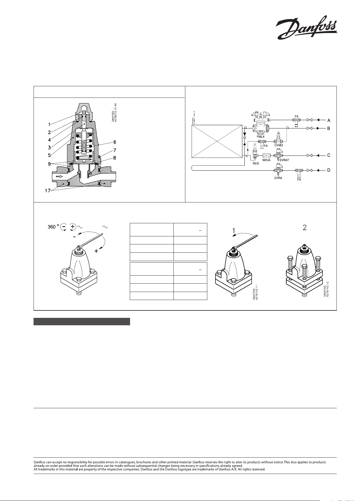
1. Protection cap
2. O-ring
3. Spindle
4. Gasket
5. Cover
6. Spring
7. Screw
8. Diaphragm
9. Gasket
17. Flanges
Fig. 1 Fig. 2
Fig. 3
0.45 bar 6.5 psi
Danfoss
M27B0003
Range
bar
–0.66 → 7 bar 0.45 bar
4 → 22 bar 1.4 bar
4 → 28 bar 2 bar
Range
psi
19.5 in.Hg → 29 psi 6.5 psi
58 psi → 319 psi 20 psi
58 psi → 406 psi 29 psi
1 turn 360°
1 turn 360°
027R9962
Δ
Δ
ENGLISH
Technical data
Refrigerants
R 717, R 22, R 134a, R 404A, R 407C etc.
Range
0 -7 bar (0-101 psig)
Max. working pressure
PB = 28 bar (406 psig)
Temperature range
−50°C to 120°C (–58°F to 248°F)
www.danfoss.com/IR
© Danfoss A/S (AC-MCI/MWA), 2013-02 DKRCI.PI.HN0.K1.02 / 520H7369 1
See g. 2
The gure shows the low pressure side of
an R 717 refrigeration plant with ooded
evaporator with pump circulation.
In this application, the constant pressure
valve, type CVMD, is mounted as a pressure regulator in the bypass line between
evaporator and downstream wet suction
line after the solenoid valve, type PMLX.
Pos. A on the drawing is the pilot line from
the high pressure side to PMLX.
Pos. B is the liquid/gas return line.
Pos. C is the liquid line to the evaporator.
Pos. D is the hot gas line for hot gas
defrosting of the evaporator.
Adjustment
See g. 3
 Loading...