

Data sheet
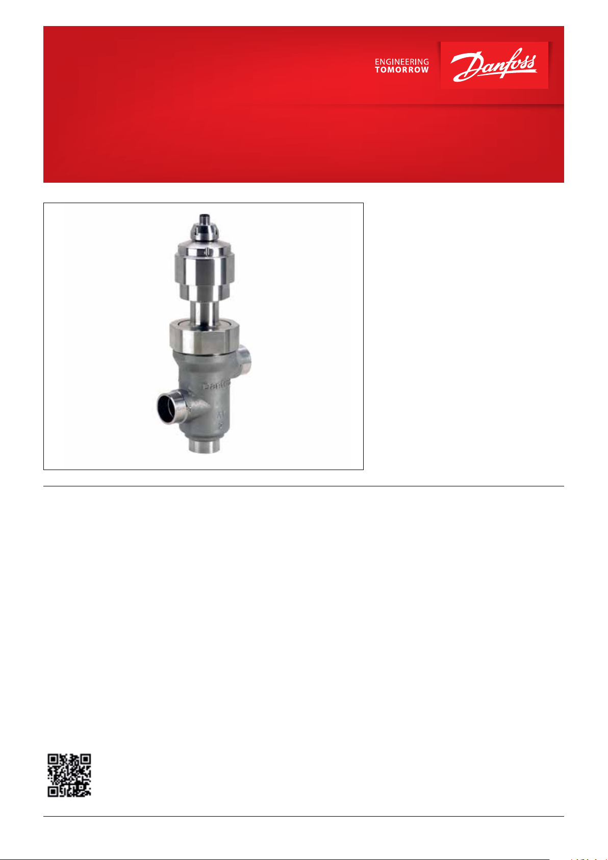
Electric 3-way valve
Type CTR 20
The CTR is an electrically operated 3-way valve
designed specically for operation in CO
with heat reclaim. CTR is designed to allow full
proportional control of the surplus heat from
compressor pack into the heat exchanger of
transcritical heat reclaim solutions.
The proportional control of the CTR ensures that
the exact amount of heat required is available at
any time, and the possibility to operate smoothly
in changeover sitiuations allowing for stable
control.
The typical application for the CTR is a Pack/
rack system in food retail application working
with transcritical CO
most attractive energy advantage of transcritical
CO
. Even as transcritical CO2 systems are on
2
par or outperform traditional HFC installations
on energy performance, this also ensures the
possibility to supply high quality heat to be
exploited. Heat reclaim is seeing an increased
deployment and becoming a norm in most
transcritical CO
. Heat reclaim is the current
2
retail installations today.
2
systems
2
Features • Full proportional and on / o control of the
heat reclaim system.
• 2 inlets and 1 outlet or 1 inlet and 2 outlets.
• Applicable to R744 and other common
refrigerants.
• CTR is compatible with oil types PAG and POE
• Full serviceable cartridge design valve.
• Modulating operation to ensure smooth
transition.
• Leak tight, motor integrated in valve.
Application:
Heat reclaim in CO
• Eliminates pressure peaks in heat reclaim
systems.
• Controls transcritical pressure up to 140 bar.
• Available for combo weld or solder/braze.
• Standard M12 connector for easy connection
to the motor driver.
• Internal / external corrosion resistant design.
• Manufactured according to ISO / TS 16943.
systems (transcritical).
2
For more information on the product,
please scan the QR code.
© Danfoss | DCS (sw) | 2018.07
DKRCC.PD.VL0.A2.02 | 1
Data sheet | Electric 3-way valve type CTR 20
Approval (in progress)
Technical data
Valve specication
Electrical specication
UL, EAC, CRN, cUL
Feature CTR 20 (DN25)
Flow 1 inlet -2 outlets or 2 inlets - 1 outlet
Refrigerant R744 (For other refrigerants please contact Danfoss)
Oil Types PAG / POE
MWP/ Refrigerant 140 bar / 2030 psig
MOPD 3 bar / 43 psi
Allowed ambient temperature range -40 – +60 °C / -40 – +140 °F
Allowed refrigerant temperature range 0 – +150 °C / +32 – +302 °F
Environment temp (Transport/Warehouse) -40 – +70 °C / -40 – +158 °F
Lifetime / endurance 10 years / 50.000 cycles in CO
Serviceable Yes
Stepper motor type Bipolar permanent motor
IP rating of electric connection 67
Step mode Microstepping (recommended), 2 phase full step
Phase resistance 52.4 ohm ±10% per coil
Inductance 85.7 mH ±20%
Current per coil 100 mA RMS / 142 mA Peak
Holding current 20% holding current (recommended)
Duty cycle 100% duty cycle is allowed
Max. total power Current driver: 1.2 Watt
Number of full steps 6600
Closing / opening time 88 sec @ 75 PPS
Step rate
Electric connector type M12
Reference position Over drive against the full close position (both top & bottom)
Overdriving in closing direction Recommended 3% of total step ie. 180 full steps
Recommended controller/driver AK-XM 208C, EKD 316, EKD 316C
Current control
75 PPS for top and bottom 10% opening / closing degree and
remaining at 250 pps
≤ 75 step /sec. (recommended)
system with 3 bar di. pressure
2
© Danfoss | DCS (sw) | 2018.07
Material of construction (Housing) Stainless Steel
Installation orientation Vertical / Horizontal (Inverted not allowed)
Valve opening characteristic Linear
DKRCC.PD.VL0.A.02 | 2
Data sheet | Electric 3-way valve type CTR 20
Ordering
Spareparts
Related products
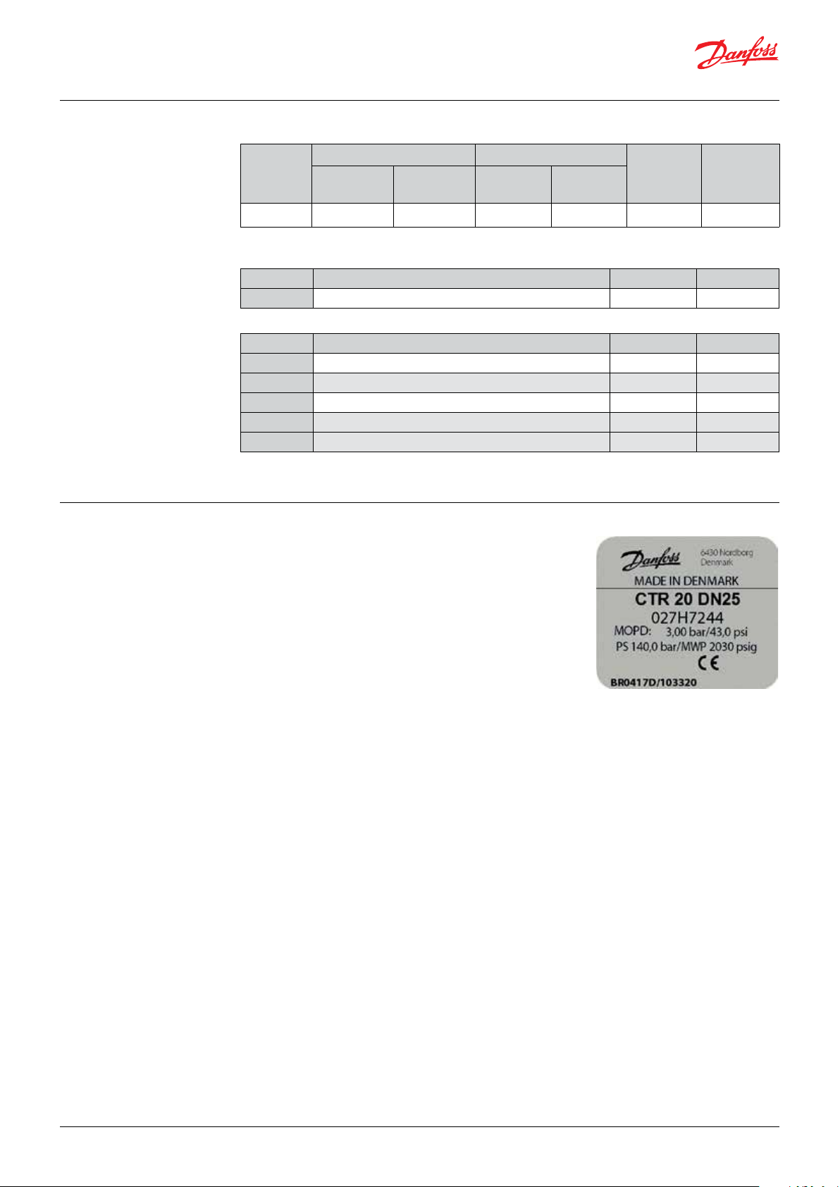
Identication, product label
Valve including actuator
Type Connection Flow rate
1
Weld
)
[inch]
CTR 20
1
) OD according to EN 10220
Type Description
Gasket O-ring spare part kit for CTR 20 (3 O-rings)
Type Description Single pack Code no.
AK-XM 208C Stepper output module 1 080Z0023
EKD 316C Superheat controller / driver (prefered EKD) 1 084B8045
EKD 316 Superheat controller / driver 1 084B8040
EKA 164A Optional display for EKD 316 1 084B8563
AST-G Manual service driver 1 034G0013
1
[inch]
1 1/
8
Solder ODF
k
[m
value
v
3
/h]
value
C
v
[gpm]
20 23.1 1
Single pack Code no
027H7244
Single pack Code no.
1 027H7248
MADE IN DENMARK : Country of origin
CTR 20 DN25 : Valve type
027H7244 : Code number
MOPD: 3,00 bar / 43.0 psi : Max. operation pressure
PS 140,0 bar / MWP 2030 psig : Max. working pressure
CE : Approval
BR0417D/103320 : (Manufactoring no.)
BR = Kolding
04 = week
17 = 2017
D = Thursday
© Danfoss | DCS (sw) | 2018.07
DKRCC.PD.VL0.A.02 | 3

34G211.10
Pr
C
Data sheet | Electric 3-way valve type CTR 20
Accessories:
M12 angle cable
M12 angle female connector is intended for use with a standard M12 male connector,
available on stepper motor valves.
This cable is designed to oer high exibility and small outer diameters with tensile strength.
The angle way M12 cable consist of paired, twisted wires, which decreases mutual inuence between
signals transmitted along the cable and reduces inuence of external sources of interference. The
cables thus provides a higher degree of protection against lost steps compared to other cables.
Approvals
Specication
Ordering
Identication
RoHS
Jacket PVC - black
Cable outer sheath Oil resistant
Water proof rating IP 67
Operating temperature range -40 – +80 °C / -40 - +176 °F
Wire type Twisted pair, cross section 20 AWG / 0.5 mm
Cable outer diameter 7.0 mm / 0.28 inch
Minimum bending radius 10 x cable diameter
Cable combustibility / test Flame retardant / VW-1 / CSA FT - 1
M12 standard EN 61076-2-101
Reference standard UL style 2464 and DIN VDE 0812
LVD directive 73/23/EEC and 93/68/EEC
Cable Cable length (L) Insulation Packing format Code no.
PVC - black
2 m / 6.6 ft SR-PVC Single pack 034G7073
8 m / 26.2 ft SR-PVC Single pack 034G7074
oduct type
ode no
2
Connections
Dimensions
A2 black
A1 white
B1 red
B2 green
34G210.10
8 meters / 26.2 feet
Manufacturing date
Meters / Feets
Country
34G209.10
Ø 63 mm / 1/4 inch
35 mm / 1.4 inch2 meters / 6.6 feet
49 mm / 1.9 inch
© Danfoss | DCS (sw) | 2018.07
DKRCC.PD.VL0.A.02 | 4

Danfoss
027H325.10
D
a
n
f
o
ss
027H325.10
Data sheet | Electric 3-way valve type CTR 20
Valve design
1. M12 connector
2. Actuator
3. Spindle
4. Valve housing
5. Connection 1
6. Connection 3
7. Connection 2
8. Valve cone
1
2
3
4
5
8
6
7
Flow direction
1 inlet 2 outlets
Connection 3 is always
common inlet
2 inlets 1 outlet
Connection 3 is always
common outlet
CTR Valve can be used in following ways
as shown in the drawings.
Danfoss
R64-3023.10
Danfoss
R64-3022.10
Danfoss
xxxx.10
Danfoss
27H002.10
© Danfoss | DCS (sw) | 2018.07
DKRCC.PD.VL0.A.02 | 5

MT Evaporator
Data sheet | Electric 3-way valve type CTR 20
Coolselector®2
is a Danfoss calculation and selection software, designed to make selection processes for all
refrigerationprojects easier and less time consuming.
For fast and precise selection of valve, use Danfoss’ CoolSelector2® software.
You can download it from http://coolselector.danfoss.com
Application example
MT/IT
Heat Recovery
o
55
C
LT Evaporator
Danfoss
R64-3024.10
AKS
AKS
AKVH
AKS
CCMT
AKS
HP High Pressure
Receiver Pressure
MT Suction Pressure
LT Suction Pressure
40oC
MM
CTR
CTR
CCMT
© Danfoss | DCS (sw) | 2018.07
In CO2 systems, the higher pressure and
temperature make it possible to recover heat
for tap water and heating. The excess heat is
removed using a gas cooler.
Regulation is carried out during transcritical and
subcritical states and the controller will control
the gas pressure/condensing pressure so that
the system achieves the optimum COP when the
recovered heat is taken into account.
The regulation of the heat recovery circuits is
done with regard to the cooling system. In the
event of conict, the safety situation is that the
cooling system has higher priority than the
recovery circuits.
The two heat recovery circuits can be considered
as independent circuits - also with regard to the
cooling system.
First, the circuit for hot tap water will take the
energy it needs to use. The remaining energy is
then available for use by the next circuit. This also
takes what is available. If there is then any excess
energy, this is removed via the gas cooler. There
must be a cooling requirement in order to supply
for heat recovery.
DKRCC.PD.VL0.A.02 | 6

Data sheet | Electric 3-way valve type CTR 20
Application example
Hot water Heat reclaim
AKS
Pump
CTR
CTR Valve provides Modulating operation to ensure smooth transition avoiding too many Compressor
on/o when going from Heat reclaim mode to full through Gas Cooler.
In the above example, the 3-way valve switches
to enable ow of hot gas to enter heat reclaim
heat exchanger. Here heat is transitioned to the
water loop hence the Hot Gas is cooled. On the
diagram, rst heat is used for Hot Tap water and
then with a second 3-way valve heat used for
55 °C 40 °C
AKS
Pump
CTR
CTR
Danfoss
27H432.10
the heating loop for the building, nally a third
3-way valve is mounted to enable by-pass of the
gas cooler if that is needed. E.g. in a very cold
season, where the pressure would drop too much
after recovering all the heat in the plate heat
exchangers.
Warning
If the pressure drop in the heat exchanger and
connecting pipes are less than 3 bar, the valve
can be installed in any way the users likes based
on the application. However, if there for some
reason is a larger pressure drop than the MOPD
of the valve then the right connection of the
valve, as shown on the following diagram, is
important for safety reasons.
Heat recovery
Danfoss
R64-3029.10
If the connections is done as shown in the
diagram, then the valve will always be able to
go out of heat recovery mode and will always
be able to let the gas cooler into operation
no matter what pressure drop is in the heat
exchanger and piping. Therefore, Danfoss advises
that the valve is always installed according to the
diagram.
© Danfoss | DCS (sw) | 2018.07
DKRCC.PD.VL0.A.02 | 7

B1
A1
A2
Flow direcon 3 - > 2
K
v
Vs % Opening
Data sheet | Electric 3-way valve type CTR 20
Flow characteristics
30
25
20
15
Value
v
K
10
5
0
Danfoss
27H440.11
5
0
10
20
15
25
35
30
40
50
45
60
55
65
75
70
80
85
Flow direcon 1 - > 3
Flow direcon 3 - > 1
Flow direcon 2 - > 3
95
90
100
Driving CTR valve CTR valve uses a bipolar, 2-phase, permanent magnet stepper motor.
CTR valve can be driven using various electronic control techniques i.e: Full step excitation mode, half
step excitation mode, micro stepping mode (recommended).
On selecting controller from other manufacturer than Danfoss, it is necessary to set the correct
valve data into the controller setting. The wrong settings may impair the performance of the valve.
a. Total no. of step
b. Step rate
c. Phase current
d. Overdriving against closing position
Note:
If the controller driving the CTR valve is from another manufacturer than Danfoss or a custom design,
the following points must be considered in order to overcome potential step loss.
To ensure total closing of the valve, and to compensate the lost steps after a dened number of
changes in opening degree, the controller should have a function to overdrive the valve in the closing
direction. It is recommended to overdrive the valve at appropriate intervals.
Cable length
Depending on the type of controller or driver, there will be limitations in cable length between the
controller / driver and the valve.
Both the actual cable length, the level of EMC emission on the location and the driver circuit have an
impact on the actual distortion of the current to the motor.
Warning
At power failure the CTR valve will remain in the actual opening position it has at the moment of
power failure, unless a device in the form of a battery backup to the controller is installed.
The following table shows the full step excitation switching
Stepper motor
switch sequence
sequence
Coil I (B) Coil II (A)
STEP
Red Green White Black
1 + - + -
CLOSING
2 + - - +
3 - + - +
4 - + + 1 + - + -
Color code is only valid for Danfoss M12 cable
OPENING
Danfoss cable connections
Pin Wire color
A1 White
A2 Black
B1 Red
B2 Green
Danfoss
B2
34G177.10
CTR valve
1
4
2
3
© Danfoss | DCS (sw) | 2018.07
DKRCC.PD.VL0.A.02 | 8

71 mm / 2.8 in
027H324.10
Dimensions and weight
360 mm / 14.2 in
Danfoss
027H323.10
/ 10.1 in
m
256 m
Related products
Electronic driver, type EKD 316 /
EKD 316C
in
/ 3.6 in
m
92.5 m
54.5 mm / 2.1
53.5 mm / 2.1 in 53.5 mm / 2.1 in
Electronic controller, type EKC 326a
and EKC 313
Electronic driver
type AK-XM 208C
Danfoss
Weight: Approx. 3.2 kg / 7.05 lbs
AKS 11 / AKS 12 temperature sensor
AKS pressure transmitter
© Danfoss | DCS (sw) | 2018.07
DKRCC.PD.VL0.A2.06 | 9
 Loading...