

Danfoss CTM 1, CTM 2 Data sheet
Data Sheet
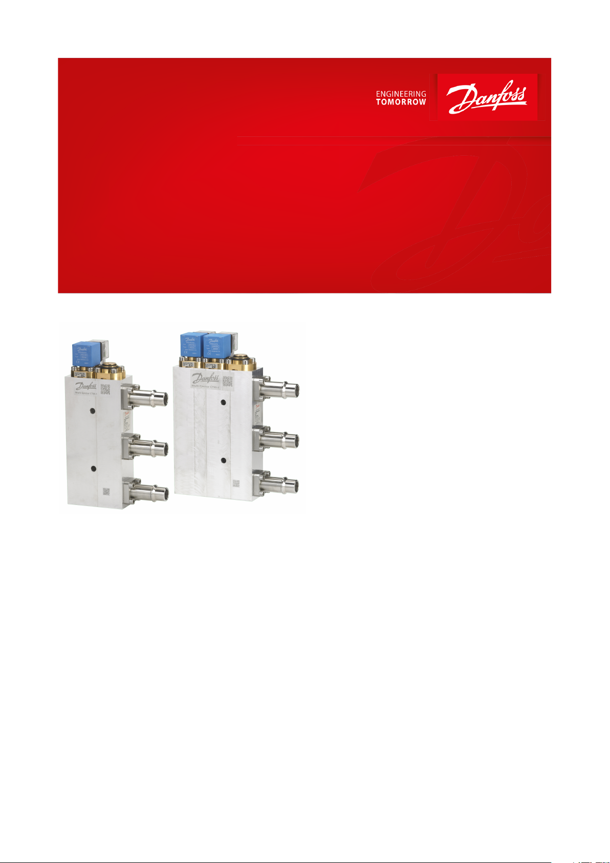
CTM Liquid valve
Type CTM 1 and CTM 2
Improves COP and lowers swept volume of the MT compressors in all CO2 systems
Liquid Ejector is a part of the CO2 Adaptive
Liquid Management (CALM), Danfoss' solution
to handle liquid in all types of transcritical CO
systems in all climates. Due to higher suction
pressure, Liquid Ejector, together with Adaptive
Liquid Control (ALC), enables lower energy
consumption and better utilization of
evaporators, resulting in operational savings.
Improved system performance results in fewer
or smaller compressors and a minimal suction
accumulator.
2
Liquid Ejector is designed for CO2 transcritical
systems to pump the CO2 liquid from the low
point in the suction accumulator back to the
receiver resulting even in 8 bar pressure lift
after mixing with gas coming from the gas
cooler.
The Liquid Ejector, AK-PC pack controllers, AKCC case controllers, and AK-SM system
manager comprise the Danfoss CALM.
AI283050886671en-000501
Pressure
Danfoss
32F996.12
P
H
P
L
P
S
P
D
P
H
P
D
P
L
P
S
1
2 3
4 5
6
7
12345
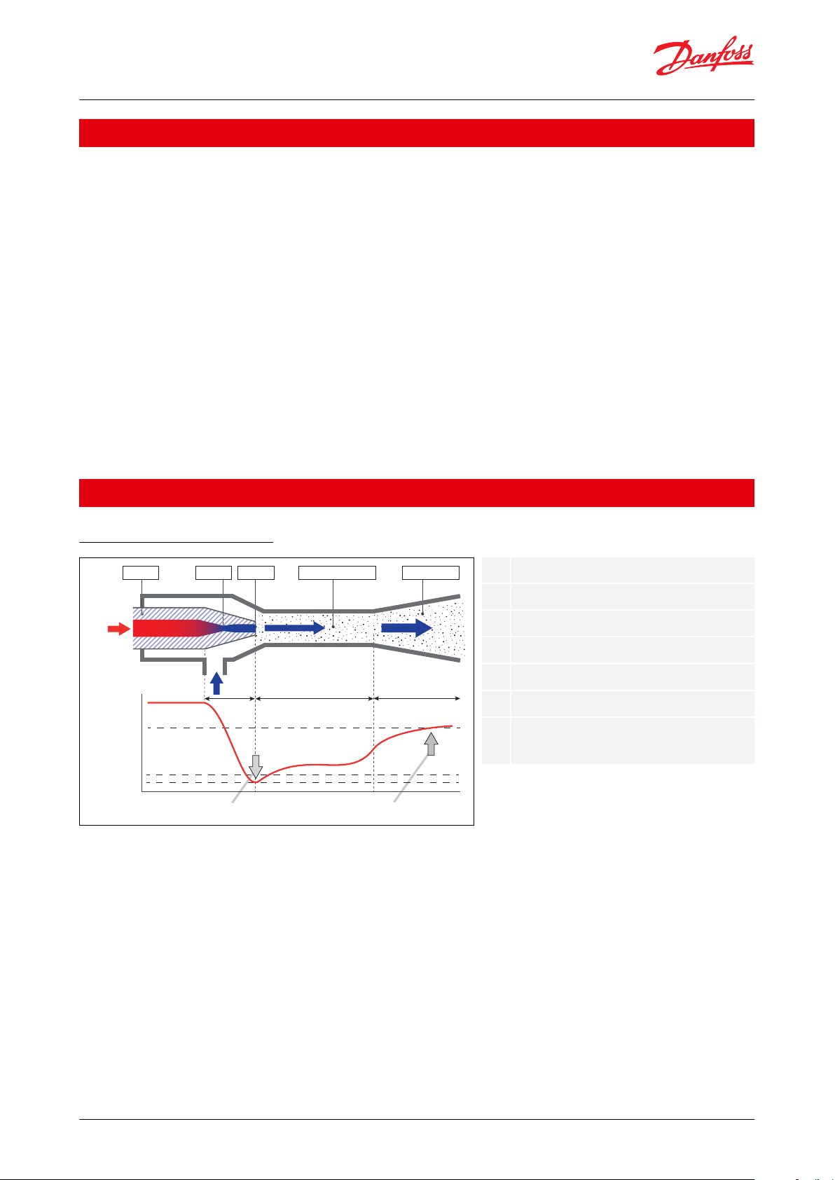
67Nozzle
Throat
Exit
Mixing chamber
Diuser
Intake due to pressure dierential
Pressure increase due to reducing ow
velocity
CTM Liquid valve , Type CTM 1 and CTM 2
Features
First Cost savings
• Lower cost compared to standard booster system due to lower swept volume of compressors (i.e. smaller
compressors or less number of compressors).
• Reliable and robust design
• Fully integrated solution not requiring any additional components like check valves or motorized ball valves
• Fully serviceable - wide range of spare parts and accessories
• Easily accessible strainer / lter for fast maintenance
• Brings rst cost savings
• Enables 5 - 10 % savings on compressor swept volume, compared to standard booster systems
Fast Pay Back – Energy saving
• Improved COP and lower swept volume to the MT compressors , resulting in lower energy consumption.
• Savings for end users
• Fast payback – lower energy consumption
• Less compressors and higher eciency on the systems, leads to shorter payback time of less than 2 years on
avarage globally
• The combination of CTM 1 and CTM 2 Liquid valve and the Danfoss CALM controllers ensure an easy setup and
commissioning, robust control of the system that ensures many years of problem free operation
Functions
The Multi Ejector function
An ejector is a device that uses expansion energy to compress another uid. In this case with the transcritical system
there is up to 20% of the compressor work that can theoretically be recovered in the expansion.
In this case with the Multi Ejector system the work is coming from the CO2 leaving the gas cooler. The high pressure
CO2 (PH) is entering the nozzle where the expansion is taking place. At the exit of the nozzle the speed is very high
and as a consequence of that the pressure is low.
This low pressure is used to drag liquid from the MT suction accumulator (PL). From there the two ows are mixed in
the mixing chamber where the pressure will be lower than at the drive inlet due to the mixing of vapour from a
higher pressure.
After the mixing the ow enters the diuser where the ow is slowed down. The shape of the diuser enables the
conversion from kinetic energy (velocity) to potential energy (pressure). After the diuser the ow is returned to the
receiver.
© Danfoss | Climate Solutions | 2021.03 AI283050886671en-000501 | 2
Danfoss
R64-2121_30
AK-PC 782A
AKVH
Medium temp. load
MBS 8250
MBS 8250
AKS 4100
AKS 11
AK-CC 550A
AKS 11
FC 103
DGS
CCMT
(ICMTS)
CCMT
(ICMTS)
MBS
8250
MBS
8250
LT
AKS 11
FC 103
Multi
Ejector
Gas cooler
AKS 11
AKS 11
Low temp. load
MBS 8250
AKS 11
AKS 32R
AKS 32R
AK-CC 550A
AKVH
AKS 11
MT
AK-SM 8xx
AKS 21A
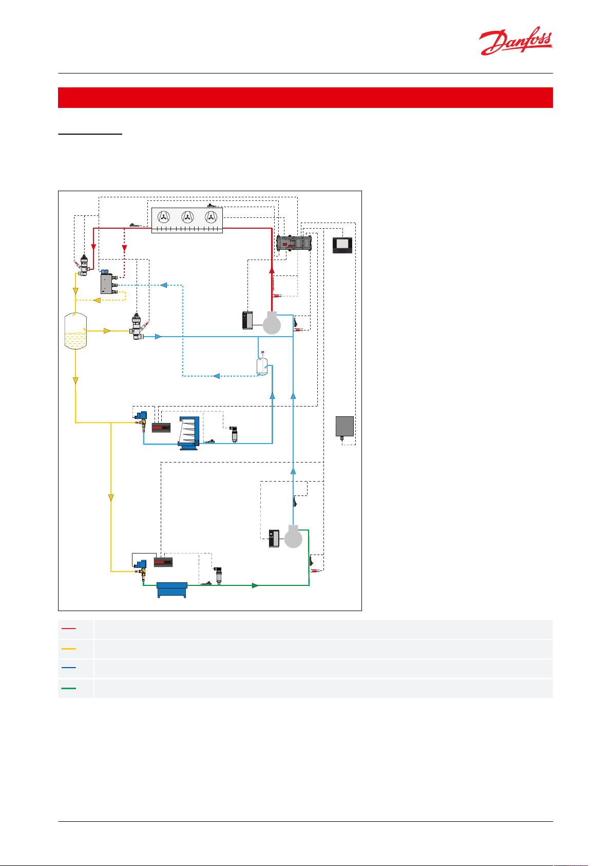
HP High Pressure (120-140 bar Max working pressure)
HP Receiver Pressure (60-90 bar Max working pressure)
LP Suction Pressure MT (35-55 bar Max working pressure)
LP Suction Pressure LT (25-30 bar Max working pressure)
CTM Liquid valve , Type CTM 1 and CTM 2
Applications
Application
The Multi Ejector is designed to lift a part of the liquid from MT suction and mix it with the gas coming from the gas
cooler at medium pressure level.
Figure 1: Application
© Danfoss | Climate Solutions | 2021.03 AI283050886671en-000501 | 3
Refrigerant
R744 with oil
Maximum working pressure
140 bar / 2031 psi
Max. test pressure
1.43 x 140 bar / 1.43 x 2031 psi
Max. OPD
90 bar / 1305 psi (for single-voltage coil, 50 Hz)
Min. OPD
< 0.1 bar / 1.45 psi
Max. pres. dif. E and C connections
20 bar / 290 psi
Media temp. range
-10 °C – +50 °C / +14 °F – 122 °F
Ambient temp. range
-10 °C – +50 °C / +14 °F – 122 °F
Humidity
0 − 100% R.H. (0-97% R.H. non-condensation condition if IP level is below IPX5)
Housing
Aluminium AW-6082 T6
Connections
Stainless steel AISI 304
Ejectors
Brass
Screws
Stainless steel A2-70
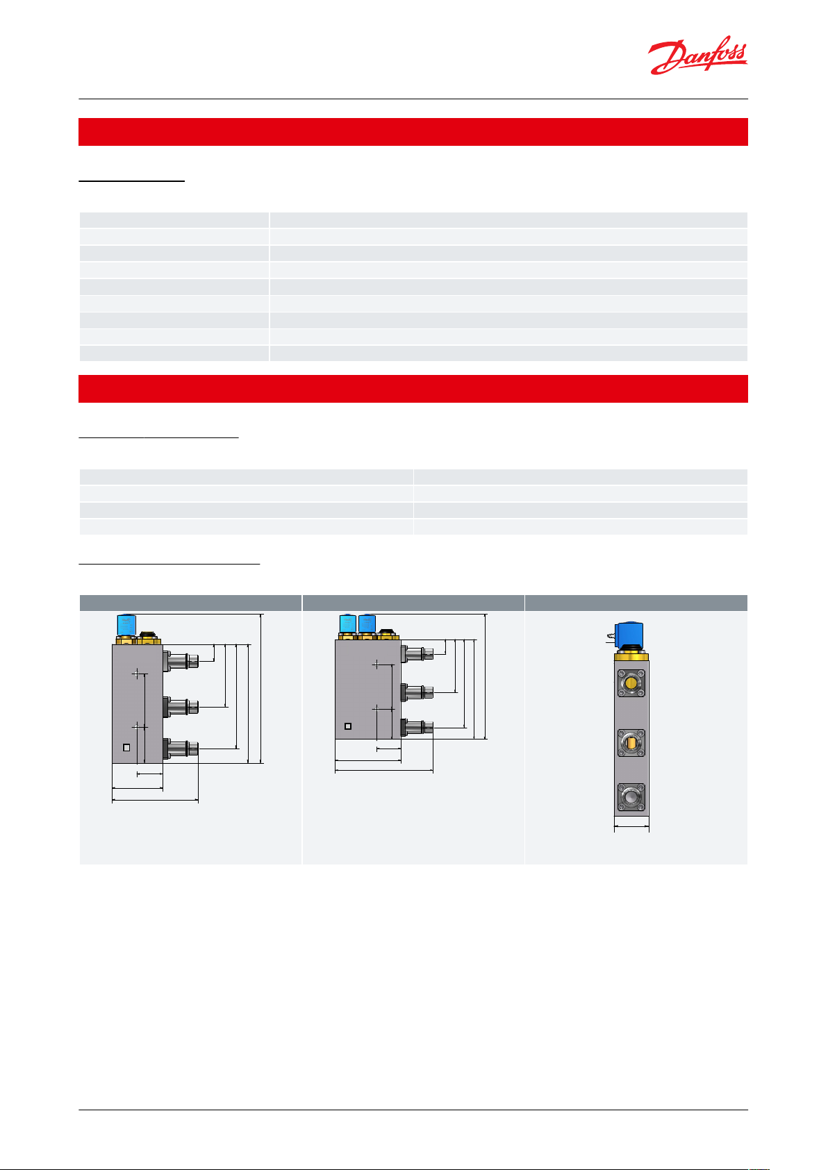
CTM 1 [Weight: 2.6 Kg / 5.7 lb]
CTM 2 [Weight: 3.6 Kg / 7.9 lb]
250.7 mm / 9.9 inch
200 mm / 7.9 inch
176 mm / 6.9 inch
106 mm / 4.2 inch
47.3 mm / 1.86 inch
92.5 mm / 3.6 inch
156.5 mm / 6.16 inch
60
90
29 mm / 1.14 inch
Danfoss
32F889.10
250.7 mm / 9.9 inch
200 mm / 7.9 inch
176 mm / 6.9 inch
106 mm / 4.2 inch
29 mm / 1.14 inch
131 mm / 5.16 inch
195 mm / 7.7 inch
47.25 mm / 1.86 inch
60
90
Danfoss
32F890.10
Danfoss
32F888.10
45 mm /
1.77 inch
CTM Liquid valve , Type CTM 1 and CTM 2
Media
Technical data
Table 1: Technical data
Product specication
Material specication
Table 2: Material specication
Dimensions and weights
Table 3: Dimensions and weights
© Danfoss | Climate Solutions | 2021.03 AI283050886671en-000501 | 4
 Loading...