

Page 1

Technical Information
PLUS+1® Connect
CS100 IoT Gateway
www.danfoss.com
Page 2

Technical Information
PLUS+1 Connect CS100 IoT Gateway — Professional Install Only
Revision history Table of revisions
Date Changed Rev
April 2021 Removed GNSS verbiage 0103
January 2021 Added output warning 0102
October 2020 First edition 0101
2 | © Danfoss | April 2021 BC299456869228en-000103
Page 3

Technical Information
PLUS+1 Connect CS100 IoT Gateway — Professional Install Only
Contents
About this Manual
About this manual............................................................................................................................................................................5
Device elements
Device Information.......................................................................................................................................................................... 6
Indicator elements........................................................................................................................................................................... 6
Type label............................................................................................................................................................................................ 7
Intended use...................................................................................................................................................................................... 7
Service and support.........................................................................................................................................................................8
Product Conformity
CS100.................................................................................................................................................................................................... 9
Compliance with CE................................................................................................................................................................... 9
Compliance with ECE R-10.......................................................................................................................................................9
PTCRB.............................................................................................................................................................................................. 9
PLUS+1® Compliance.................................................................................................................................................................9
Safety information
General information......................................................................................................................................................................10
Safety advice....................................................................................................................................................................................10
Avoid property damage.............................................................................................................................................................. 11
Connecting the supply voltage...........................................................................................................................................12
Polarity reversal.........................................................................................................................................................................12
IP protection rating..................................................................................................................................................................12
Welding guidelines.................................................................................................................................................................. 12
Warranty and liability....................................................................................................................................................................12
Servicing the CS100.................................................................................................................................................................12
Ordering information
Part number.....................................................................................................................................................................................13
Related products............................................................................................................................................................................13
Device Functions
Available variants & functions...................................................................................................................................................14
Operating modes...........................................................................................................................................................................14
GNSS (Global Navigation Satellite System)...........................................................................................................................14
Wireless Solution............................................................................................................................................................................14
SIM card.............................................................................................................................................................................................14
Input/output functions (I/O)......................................................................................................................................................14
CAN interfaces.................................................................................................................................................................................15
Device configuration.................................................................................................................................................................... 15
CS100 firmware update............................................................................................................................................................... 15
Secure connection to the PLUS+1 Connect portal............................................................................................................15
Connector
Main connector...............................................................................................................................................................................16
CS100 Technical Data
Electrical Data..................................................................................................................................................................................17
Mechanical Data.............................................................................................................................................................................17
Interface/Protocol/Certification................................................................................................................................................17
Multifunction inputs..................................................................................................................................................................... 18
Outputs..............................................................................................................................................................................................19
PLUS+1® Connect portal
Problem with connection to PLUS+1® Connect portal.................................................................................................... 20
Packaging and Transport
IP protection rating....................................................................................................................................................................... 21
Disposal............................................................................................................................................................................................. 21
CS100 Technical Drawings
CS100 Dimensions.........................................................................................................................................................................22
CS100 Cable..................................................................................................................................................................................... 22
©
Danfoss | April 2021 BC299456869228en-000103 | 3
Page 4

Technical Information
PLUS+1 Connect CS100 IoT Gateway — Professional Install Only
Contents
Mounting
Inside mount....................................................................................................................................................................................23
Top Mount........................................................................................................................................................................................23
4 | © Danfoss | April 2021 BC299456869228en-000103
Page 5

Technical Information
PLUS+1 Connect CS100 IoT Gateway — Professional Install Only
About this Manual
About this manual
This document is part of the product and provides important information on the intended use, safety,
installation and operation of the device(s) described below. The manual is intended for qualified
technicians and electricians with advanced knowledge in electrical engineering and fieldbus systems,
allowing them to estimate the risks and hazards of operating the device and to integrate it into systems
with components of other manufacturers.
The qualified personnel must know the contents of this manual and have access to it at all times.
©
Danfoss | April 2021 BC299456869228en-000103 | 5
Page 6
1
2
3
4
5
C
Technical Information
PLUS+1 Connect CS100 IoT Gateway — Professional Install Only
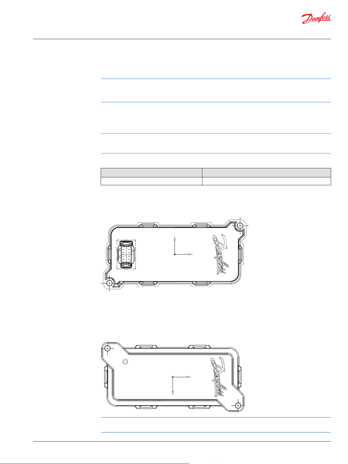
Device elements
This chapter gives an overview of the device elements, functions and describes the intended use. It
further lists the available device variants and the product certifications.
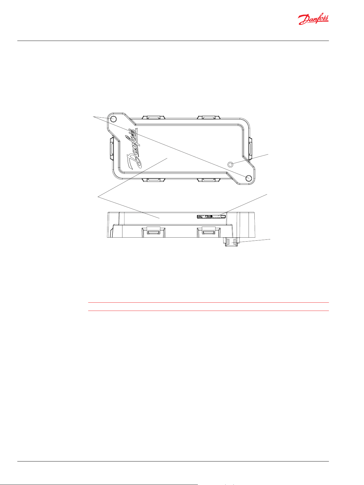
Device Information
The device elements for the CS100
Indicator elements
1. Mounting holes
2. Housing
3. Status LED
4. Type label
5. 8 Pin DEUTSCH connector
Caution
This device is not field serviceable. Opening the housing will void the warranty.
The device is equipped with the indicator element: 1x Device State multicolor LED.
6 | © Danfoss | April 2021 BC299456869228en-000103
Page 7
C
W
Technical Information
PLUS+1 Connect CS100 IoT Gateway — Professional Install Only
Device elements
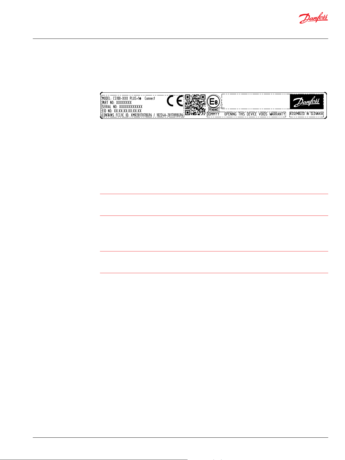
Type label
The CS100 type label is located on the side of the enclosure.
CS100 type label information
•
Model
•
Part number
•
Serial number
•
E-mark certification number
•
CE Mark
•
Country of Origin
•
Traceability code in data matrix code
Caution
Intended use
The device type label contains important information and should not be removed. Solvents can destroy
the label imprint.
Do not contact the type label with any solvent-containing substance.
Warning
Danger due to possibility of deficient data transmissions. This device operates using radio signals and
cellular networks.
Do not us this device for safety-related applications.
Insufficient mobile radio network availability, interference, failure or malfunction of the device may lead
to faulty data transmission. Because of this, data transmission cannot be guaranteed always and under all
conditions.
•
Do not operate the device in machines and applications where life depends on the proper (fault-free)
operation of this device.
•
Never rely solely on wireless device for essential communications, the CS100 is not designed for
safety related applications.
•
This device is designed to be used in systems which must be checked for conformity with legal
requirements prior to placing into operation.
•
Only qualified technicians and electricians with advanced knowledge of electrical engineering and
fieldbus systems should put this device into operation. The integrator of this device is responsible to
check and comply with regional directives and requirements.
•
The device can be used in environments that require protection class IP69k.
•
IP69k protection is only ensured if all connectors are plugged in or covered with suitable protection
caps.
•
Before exposing the device to dust and water, plug in all connectors.
•
Do not immerse the device in water or other liquids.
The OEM of a machine or vehicle in which PLUS+1® or others electronic controls are installed has the full
responsibility for all consequences that may occur.
©
Danfoss | April 2021 BC299456869228en-000103 | 7
Page 8

C
Technical Information
PLUS+1 Connect CS100 IoT Gateway — Professional Install Only
Device elements
•
Danfoss has no responsibility for any consequences (direct or indirect) caused by failures or
malfunctions.
•
Danfoss has no responsibility for any accidents caused by incorrectly mounted or maintained
equipment.
•
Danfoss does not assume any responsibility for PLUS+1® products being incorrectly applied or the
system being programmed in a manner that jeopardizes safety.
•
All safety critical systems shall include an emergency stop to switch off the main supply voltage for
the outputs of the electronic control system. All safety critical components shall be installed in such a
way that the main supply voltage can be switched off at any time. The emergency stop must be easily
accessible to the operator.
•
A system FMEA should be performed on all applications.
CS100 interfaces are designed for transmitting data that is available within a CAN network via LTE 4G
Cat.M1, additionally via GSM/GPRS/EDGE.
The interfaces are suitable for use in mobile and stationary systems for industry, small business area, and
in agricultural and forestry machinery. Featured is an easy-to-install plastic enclosure which can be bolted
to a panel.
The devices have integrated antennas and must be installed properly to the machine to avoid bolt
interference and to ensure the recommended line of sight to the sky.
Service and support
Contact PLUS+1® Support and Services:
https://www.danfoss.com/en/products/software/dps/plus1-software-services-support-and-training/plus1support-and-services/#tab-overview
The most recent driver, firmware, tools and documentation versions are available for download from
https://www.danfoss.com/en/products/software/?sort=default_sort
Caution
Warranty will be voided if device is opened.
Device is not field serviceable. Do not open the device.
8 | © Danfoss | April 2021 BC299456869228en-000103
Page 9
Technical Information
PLUS+1 Connect CS100 IoT Gateway — Professional Install Only
Product Conformity
CS100
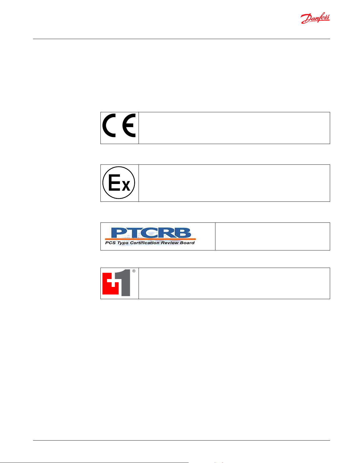
Compliance with CE
This device complies with the directives, standards, and normative documents. Directive
2014/53/EU on Radio equipment and telecommunications terminal equipment
Directive 2004/108/EC on Electromagnetic compatibility
Immunity standard for industrial environments (EN 61000-6-2 (2006)
Emission standard for industrial environments (EN 61000-6-3 (2007)
Compliance with ECE R-10
This device has been approved to comply with Regulation No. 10. ECE Regulation No. 10
(Revision 3, 14/08/2008) Approval No.: 10 R-XXXXXX
PTCRB
PLUS+1® Compliance
Danfoss CS100 is compliant with PLUS+1® System Control Platform.
Danfoss Telematics features are added in the Remote Interface (Machine information, signal
strength, geographical position linked to Google Maps, CAN Status).
This device has been certified for use on PTCRB Mobile
Network Operator networks.
For more information, see the certified device section
http//ptcrb.com
©
Danfoss | April 2021 BC299456869228en-000103 | 9
Page 10

W
Technical Information
PLUS+1 Connect CS100 IoT Gateway — Professional Install Only
Safety information
In this chapter, you will find important information on how to avoid life-threatening situations and
injuries and how to prevent product damage.
General information
These instructions are part of the device.
They contain text and illustrations for the correct handling of the module and must be read before
installation or use.
Before deploying the device described in this document, read the entire Technical Information and the
User Manual document, including all safety information.
Non-observance of the notes, operation that is not in accordance with use as prescribed below, wrong
installation or handling can result in serious harm concerning the safety of people and plant.
Keep this manual for future use and make all information available to anyone deploying the device, even
after installation.
Tampering with the device can lead to considerable risks for the safety of people and plant. It is not
permitted and leads to an exclusion of any liability and warranty claims.
The device must be installed, connected and put into operation by a qualified electrician.
In the event of malfunctions or uncertainties, please contact the manufacturer.
This device is designed to be used in systems which must be checked for conformity with legal
requirements prior to placing into operation. The integrator of this device is responsible to check and
comply with regional directives and requirements.
Safety advice
Warning
Danfoss strongly recommends that initialization and provisioning of CS100 IoT Gateways be completed
outside of machine production processes. It is best practice to de-couple this initialization and
provisioning from machine production processes.
General
Danger due to possibly deficient data transmission.
CS100 unit operates using radio signals and cellular networks and is not authorized for use in safety-
related applications.
Deficient network coverage, failure or malfunction of the device may lead to deficient data transmission.
Because of this, connection cannot be guaranteed at all times under all conditions.
•
Do not operate the device in machines and applications where life depends on the proper operation
of this piece of equipment.
•
Never rely solely upon any wireless device for essential communications.
Health care
Danger of interference caused by RF energy.
Medical equipment may be sensitive to RF energy.
10 | © Danfoss | April 2021 BC299456869228en-000103
Page 11

W
Technical Information
PLUS+1 Connect CS100 IoT Gateway — Professional Install Only
Safety information
•
When in a hospital or other health care facility, observe the restrictions on the use of cellular
communication equipment. Switch CS100 unit off, if instructed to do so by the guidelines posted in
sensitive areas.
The operation of cardiac pacemakers, other implanted medical device and hearing aids can be affected
by interference from CS100 unit's antennas placed close to the device.
•
If in doubt about potential danger, contact a physician or the manufacturer of the implanted medical
device to verify that it is properly shielded. Pacemaker patients are advised to keep CS100 unit and its
antennas away from the pacemaker while it is on.
Air traffic
Danger of interference caused by RF energy.
The operation of wireless appliances in an aircraft is forbidden to prevent interference with
communications systems. Failure to observe these instructions may lead to the suspension or denial of
cellular services to the offender, legal action, or both.
•
Switch the unit off before boarding an aircraft.
•
Make sure it cannot be switched on inadvertently.
Explosives
Danger of explosion.
Operation of any electrical equipment in potentially explosive atmospheres can constitute a safety
hazard.
•
Observe the applicable regulations and precautions when you are near explosive areas (i.e. petrol
stations, fuel depots, chemical plants or where blasting operations are in progress).
•
Do not mount the antenna in the close environment of fuel tanks, vessels with explosives and
insufficiently shielded electronic devices.
Antennas
Danger due to absorption of RF energy.
Mobile communication devices may pose a health risk when operated in the close proximity of persons.
•
Install the device with integrated antenna(s) used for the CS100 to provide a separation distance of at
least 20 cm / 8 inches from all persons.
•
Do not operate them in conjunction or co-locate them with any other antenna or transmitter.
Electronic equipment
Danger of interference caused by RF energy
The unit receives and transmits radio frequency energy while switched on. Interference may occur if it is
used close to TV sets, radios, computers or inadequately shielded equipment.
Follow any special regulations and always switch off the unit wherever use is forbidden, or when you
suspect that it may cause interference or danger.
Avoid property damage
Warning
Property damage may occur and unintended movement of machine or mechanism may cause injury to
the technician or bystanders.
Before any installation of the Control system, turn ignition lock off and disconnect the battery. Before
handling the device disconnect externally. Also, disconnect independently supplied output load circuits.
©
Danfoss | April 2021 BC299456869228en-000103 | 11
Page 12

W
W
Technical Information
PLUS+1 Connect CS100 IoT Gateway — Professional Install Only
Safety information
Connecting the supply voltage
The supply voltage must be within the operating range. Connect the supply voltage to power supply.
Protect the module by using a fuse with requisite fuse level: 2 amps. To avoid damage, switch off power
to the device when connecting/disconnecting the main connector to the device.
The CS100 and control system must be connected to the same power supply and ground connection to
ensure trouble free communication.
Polarity reversal
Polarity reversal can damage the unit. Protect the CS100 module against power supply polarity reversal
by using an external fuse, maximum 2 amps.
IP protection rating
IP 67 rating is ensured only with the following guidelines:
•
Do not expose the device to dust and water if the connectors are not plugged in.
•
Do not immerse the device in water or other liquids.
•
Do not operate the device unless temperature is between -40 °C and +75 °C (-40 °F and +167 °F).
•
Do not store and/or transport the device unless it is kept at a temperature between -40 °C and +85 °C
(-40 °F and +185 °F).
Warranty and liability
Welding guidelines
Welding should be done before the installation of the control system.
The following is recommended when welding on a machine equipped with electronic components:
•
Turn the engine off.
•
Remove electronic components from the machine before any arc welding.
•
Disconnect the negative battery cable from the battery.
•
Do not use electrical components to ground the welder.
•
Clamp the ground cable for the welder to the component that will be welded as close as possible to
the weld.
We assume no liability for defects caused by normal wear, external influences, and errors of installation,
operating or maintenance. This also applies if the customer itself or third parties without our approval
modify the components of our products (e.g. devices, elements or additional hardware facilities;
programs or program elements of the software).
Servicing the CS100
Warning
The device can only be repaired by the manufacturer, it is not field serviceable. Opening the device
housing will void the Warranty.
Warning
To prevent misuse, immediately inform Danfoss in case of loss or theft of the device or the related SIM
card that is factory pre-installed on it.
12 | © Danfoss | April 2021 BC299456869228en-000103
Page 13

Technical Information
PLUS+1 Connect CS100 IoT Gateway — Professional Install Only
Ordering information
Part number
Device and part number
CS100 IoT Gateway
Related products
Related product and part numbers
DEUTSCH mating connector bag assembly
11230826
K29620
(16-20 AWG)
©
Danfoss | April 2021 BC299456869228en-000103 | 13
Page 14

Technical Information
PLUS+1 Connect CS100 IoT Gateway — Professional Install Only
Device Functions
Available variants & functions
Variant GNSS CAN Bus
CS100 Yes 2 2 Yes Yes Yes
Operating modes
CS100 devices operate in Data Logging mode.
Data logging
In this operation mode the CS100 unit logs specific CAN messages, GNSS position data and internal
variables according to its configuration and sends them to the Danfoss PLUS+1® Connect portal.
CS100 devices have an internal non-volatile memory which allow CS100 to store the logged data in case
of a cellular outage. When the cellular connection is recovered the logged data are sent to the Danfoss
PLUS+1® Connect portal automatically.
GNSS (Global Navigation Satellite System)
The GNSS enables the devices to determine their position using the Global Positioning System (GPS). The
position data can then be transmitted via the cellular connection to the Danfoss PLUS+1® Connect portal.
The device includes a GNSS receiver for determining position data: the receiver can process signals from
GPS, GLONASS, and BeiDou satellites. It can process data from multiple navigation systems
simultaneously: this increases the accuracy.
The CS100 uses GNSS as a time source. When GNSS sync is not available, the local timing accuracy is ±2
seconds per day.
Interface
Local MFIO RTC Data Logging Power
Management
Wireless Solution
CS100 interfaces transmit data available on a CAN bus via LTE Cat.M1 and 2G telecommunication
services.
Beyond the LTE Cat.M1/GSM functionality, these services allow for communication with web servers at
higher data rates. The communication is based on the TCP/IP protocol, the communication is encrypted
and secure (TLS). Using these services requires a connection to a Danfoss PLUS+1 Connect portal.
SIM card
Factory installed into the device there is a network operator SIM card.
Inserting generic SIM card is not possible because the housing cannot be opened.
The functionality depending on the ambient temperature can be assured for the maximum transfer rate
only between -38 °C to 55 °C (36.4 °F to 131 °F).
Input/output functions (I/O)
CS100 feature two multifunction input/output (2 DIN/AIN/ResIN/FreqIN/CrntIN/DOut) configurable with
several options like the same type of pins available on PLUS+1 ECUs. You can use the input function, for
instance, to read and log status information from devices or machines as well as to directly determine
and monitor switch and key states. You can send the data from the input/output function via the CAN
bus or via the mobile radio network.
14 | © Danfoss | April 2021 BC299456869228en-000103
Page 15

Technical Information
PLUS+1 Connect CS100 IoT Gateway — Professional Install Only
Device Functions
CAN interfaces
The device features 2 CAN Bus interfaces. The CAN interfaces meet the specifications CAN 2.0 A/B
protocol and the physical layer according to ISO 11898-2 high-speed up to 1 Mbit / s. The CAN interfaces
are operational only when existing power supply is energized. A support for CAN-FD is not possible.
Device configuration
The CS100 can be remotely configured from the Danfoss PLUS+1® Connect portal to monitor the
machine state, performance, and position. Both position and machine data are periodically transmitted
and stored to the Danfoss Data Portal.
CS100 firmware update
You can load a firmware update to the CS100 via the Danfoss PLUS+1® Connect portal. The firmware
update may reset the saved configuration to default. After the firmware update, load your configuration
to the device through the PLUS+1® Connect portal.
Secure connection to the PLUS+1 Connect portal
CS100 always establishes a secure encrypted TLS connection to the PLUS+1 Connect portal. If, for specific
reasons, the encryption is a problem, please contact your Danfoss representative for possible solutions.
©
Danfoss | April 2021 BC299456869228en-000103 | 15
Page 16
Technical Information
PLUS+1 Connect CS100 IoT Gateway — Professional Install Only
Connector
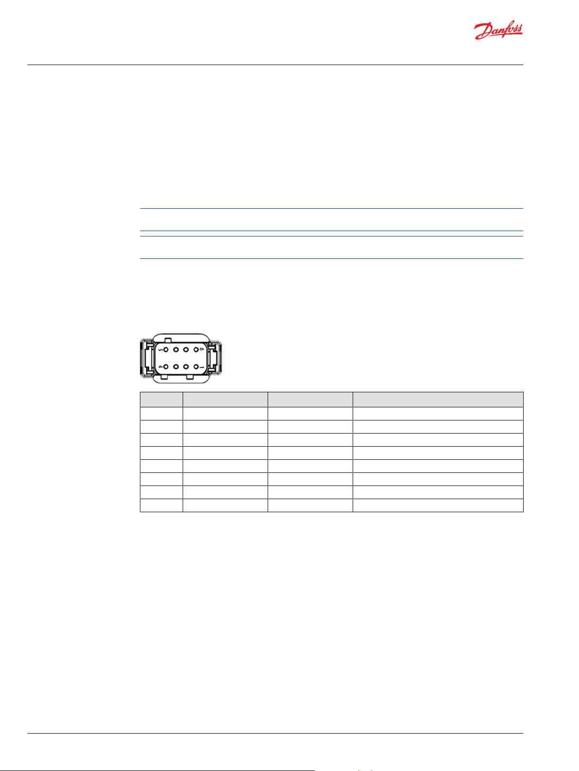
CS100 is equipped with: 1x Main connector (CAN Bus, I/O, Power).
Main connector
The connector functions:
•
Connecting the device to the CAN bus network
•
Supplying the device with power
•
Local multifunction Inputs/Outputs
To avoid damage to the device, connect/disconnect the main connector only if the power supply to the
device is switched off.
To maximize the performance of the GPS receiver, mount the GPS antenna in a place where it is level with
the local geographic horizon and has full view of the sky above.
8-pin DEUTSCH CAN/power supply/local MFIO
The table and drawing below show the pin assignment and conductor colors of the connector. The colors
stated in the table below are the conductor colors of the cable listed.
Power supply/ CAN bus/ I/O connector
Pin Designation Color Description
1 Ground Black Power Supply
2 9 to 36 Vdc Red Power Supply
3 CAN 1 high Yellow CAN bus 1
4 CAN 1 low Green CAN bus 1
5 MFIO1/CL15 Brown Multifunction IO/Ignition
6 MFIO2 Orange Multifunction IO
7 CAN 2 high Yellow/White CAN bus 2
8 CAN 2 low Green/White CAN bus 2
16 | © Danfoss | April 2021 BC299456869228en-000103
Page 17
Technical Information
PLUS+1 Connect CS100 IoT Gateway — Professional Install Only
CS100 Technical Data
Electrical Data
Electrical data
DC supply voltage
Memory buffering capacity
EMI/RFI rating
Mechanical Data
Mechanical data
Dimension L x W x D
Housing
Color
Operating temperature
Storage temperature
IP rating
Weight
Status LED
9 to 36 Vdc
16 MB
100 V/m
177 x 86 x 41 mm
Tamper resistant
Black
-40 to 75°C [-40 to 167°F]
-40 to 85°C [-40 to 185°F]
IP67 (with connector mated)
IP69k (when top mounted and with connector plugged in or
suitably capped)
250 grams
1 Multi-color
Interface/Protocol/Certification
Interface/Protocol/Certification
CAN bus network
Multifunction Input/Output
Radio Module
Cat M1 Throughput (UL/DL)
2G-EGPRS Throughput (UL/DL)
Cat M1 LTE FDD Bands
2G – EGPRS Bands
GNSS Constellations
Antennas
SIM Card
Certifications
Vibrations
Shock
2 (ISO 11898-2 High Speed, 2.0A/B)
2 (DIN/AIN/ResIN/FreqIN/CrntIN/CL15/DOUT)
LTE Cat M1 and 2G cellular
Max 375 kbps / Max 375 kbps
Max 236.8 kbps / Max 296 kbps
B1/B2/B3/B4/B5/B8/B12/B13/B18/B19/B20/B26/B28
850/900/1800/1900 MHz
GPS, GLONASS, BeiDou, Galileo
Cellular and GNSS (Internal)
Factory Installed
PTCRB, RED, CE, E-Mark
IEC 60068-2-64
IEC 60068-2-27 test Ea
©
Danfoss | April 2021 BC299456869228en-000103 | 17
Page 18
Technical Information
PLUS+1 Connect CS100 IoT Gateway — Professional Install Only
CS100 Technical Data
Multifunction inputs
Middle range analog
Description Unit Minimum Typical Maximum Comment
Minimum discernible voltage mV — — 20 —
Maximum discernible voltage V 5.18 5.26 5.33 —
Resolution mV — 1.3 — —
Worst case offset and gain error mV — — 71 VMeasure = 5.26 V
Non-linearity mV — — ±7.8 —
Input impedance kΩ 232 233 234 No pull up or pull down
Input impedance (5V/GND) kΩ 13.9 14.1 14.3 Pull up or pull down
Input impedance (2.5V) kΩ 7.1 7.3 7.4 Pull up and pull down
High range analog
Description Unit Minimum Typical Maximum Comment
Minimum discernible voltage mV — — 145 —
Maximum discernible voltage V 34.5 35.3 36.1 —
Resolution mV — 8.6 — —
Worst case offset and gain error V — — .79 VMeasure = 35.5 V
Non-linearity mV — — ±53 —
Input impedance kΩ 109.1 109.3 109.5 No pull up or pull down (Vin < 5.7 V)
Input impedance (5V/GND) kΩ 13.0 13.2 13.4 Pull up or pull down (Vin < 5.7 V)
Input impedance (2.5V) kΩ 6.9 7.0 7.1 Pull up and pull down (Vin < 5.7 V)
Frequency input middle range
Description Unit Minimum Typical Maximum Comment
Range Hz 0 — 10000 In steps of 1 Hz
Range (phase and quad) Hz 0 — 5000 In steps of 1 Hz
Rising voltage threshold V — — 3.89 Voltage required for frequency input
Falling voltage threshold V 0.85 — — Voltage required for frequency input
Input impedance kΩ 232 233 234 No pull up or pull down
Input impedance (5V/GND) kΩ 13.9 14.1 14.3 Pull up or pull down
Input impedance (2.5V) kΩ 7.1 7.3 7.4 Pull up and pull down
Frequency (PPU) High Range
Description Unit Minimum Typical Maximum Comment
Range Hz 0 — 10000 In steps of 1 Hz
Range (phase and quad) Hz 0 — 5000 In steps of 1 Hz
Rising voltage threshold V — — 23.6 Voltage required for frequency input
Falling voltage threshold V 5.6 — — Voltage required for frequency input
Input impedance kΩ 109.1 109.3 109.5 No pull up or pull down
Input impedance (5V/GND) kΩ 13 13.2 13.4 Pull up or pull down
Input impedance (2.5V) kΩ 6.9 7.0 7.1 Pull up and pull down
18 | © Danfoss | April 2021 BC299456869228en-000103
Page 19

W
Technical Information
PLUS+1 Connect CS100 IoT Gateway — Professional Install Only
CS100 Technical Data
Resistance input
Description Unit Minimum Typical Maximum Comment
Range Ω 5.2 — 10000 In steps of 1 Ω
Measurement error % — — 6.4 100Ω
— — 1.9 1kΩ
— — 4.9 10kΩ
Input impedance kΩ 1.32 1.32 1.33 Input impedance to 5V
Outputs
Digital output
Description Unit Minimum Typical Maximum Comment
Output Voltage range V 0
Current mA 0 — 500 Each output pin capable of driving 500mA. No
-10.3
-22.3
@Vin=12v & 500ma
@Vin= 24V & 500ma
current limiting; damage may be done if the load
pulls more than 500mA.
Warning
DOUT pins have short circuit protection but are NOT current limited. Exceeding 500mA per pin could
damage the CS100.
©
Danfoss | April 2021 BC299456869228en-000103 | 19
Page 20

Technical Information
PLUS+1 Connect CS100 IoT Gateway — Professional Install Only
PLUS+1® Connect portal
The CS100 is produced with a pre-installed SIM card and with a default configuration that allows the
direct connection of the device to the PLUS+1® Connect portal.
The visibility of the device on the PLUS+1® Connect portal is linked to the activation of the device, if not
activated with a specific data plan the device is not visible on the portal.
Connect the device and ensure the device turns on.
The LED light correct sequence:
The LED lights up green constantly during the first second.
•
The LED starts to flash.
•
Problem with connection to PLUS+1® Connect portal
After connecting to power supply, the LED should then follow the correct sequence. If the LED lights up
green and becomes red or stops during one of the steps, there is a problem. Contact the helpdesk or your
CS PAE. EID number is required in order to help you.
20 | © Danfoss | April 2021 BC299456869228en-000103
Page 21

Technical Information
PLUS+1 Connect CS100 IoT Gateway — Professional Install Only
Packaging and Transport
IP protection rating
IP 67 rating is ensured only with the following guidelines:
•
Do not expose the device to dust and water if the connectors are not plugged in.
•
Do not immerse the device in water or other liquids.
•
Do not operate the device unless temperature is between -40 °C and +75 °C (-40 °F and +167 °F).
•
Do not store and/or transport the device unless it is kept at a temperature between -40 °C and +85 °C
(-40 °F and +185 °F).
Disposal
Observe national regulations when disposing the device, accessories and its package.
©
Danfoss | April 2021 BC299456869228en-000103 | 21
Page 22

177.70 [7.00]
162.00 [6.38]
86.10 [3.40]
71.00 [2.80]
30.42 [1.20]
40.90 [1.61]
2 X Ø 6.3 THRU
9.30 [0.37]
36.0 [1.42]
17.5 [0.69]
23.0 [0.1]
A
Pin 1
Pin 8
Pin 5 Pin 4
5 Meter ± 10 mm
Technical Information
PLUS+1 Connect CS100 IoT Gateway — Professional Install Only
CS100 Technical Drawings
CS100 Dimensions
CS100 dimensions in mm [in]
CS100 Cable
A Minimal panel cutout
22 | © Danfoss | April 2021 BC299456869228en-000103
Page 23
C
Technical Information
PLUS+1 Connect CS100 IoT Gateway — Professional Install Only
Mounting
The device can be directly bolted into spaced drill holes, see CS100 Technical Drawings on page 22. The
device can be mounted in any position, Top Mount on page 23 is recommended.
The devices have integrated antennas and must be installed properly to the machine to avoid bolt
interference and to ensure the recommended line of sight to the sky.
Excessively long bolts, or metallic elements in general, may interfere with radio signal.
Care must be taken to insure that the module connector is positioned so that moisture drains away from
the connector. Provide a drip loop in the harness. Provide strain relief for mating connector wires.
Caution
Module damage may occur.
Use caution when installing modules. It's possible to damage the module if excessive pressure is applied
during the installation of harness strain relief.
Fasteners
Recommended outer diameter (OD) Recommended torque
6.0 mm (0.25 in) 2.26 N•m (20 in•lbs)
Inside mount
Top Mount
Simple mounting option
The connector is facing inward through mounting surface, which allows for mounting on top of the
machine for best antenna exposure.
Recommended mounting option
Raises to IP69k rating, when top mounted and connector is plugged in (or suitably capped for
protection).
©
Danfoss | April 2021 BC299456869228en-000103 | 23
Page 24

Danfoss
Power Solutions GmbH & Co. OHG
Krokamp 35
D-24539 Neumünster, Germany
Phone: +49 4321 871 0
Danfoss
Power Solutions ApS
Nordborgvej 81
DK-6430 Nordborg, Denmark
Phone: +45 7488 2222
Danfoss
Power Solutions (US) Company
2800 East 13th Street
Ames, IA 50010, USA
Phone: +1 515 239 6000
Danfoss
Power Solutions Trading
(Shanghai) Co., Ltd.
Building #22, No. 1000 Jin Hai Rd
Jin Qiao, Pudong New District
Shanghai, China 201206
Phone: +86 21 2080 6201
Products we offer:
Hydro-Gear
www.hydro-gear.com
Daikin-Sauer-Danfoss
www.daikin-sauer-danfoss.com
Cartridge valves
•
DCV directional control
•
valves
Electric converters
•
Electric machines
•
Electric motors
•
Gear motors
•
Gear pumps
•
Hydraulic integrated
•
circuits (HICs)
Hydrostatic motors
•
Hydrostatic pumps
•
Orbital motors
•
PLUS+1® controllers
•
PLUS+1® displays
•
PLUS+1® joysticks and
•
pedals
PLUS+1® operator
•
interfaces
PLUS+1® sensors
•
PLUS+1® software
•
PLUS+1® software services,
•
support and training
Position controls and
•
sensors
PVG proportional valves
•
Steering components and
•
systems
Telematics
•
Danfoss Power Solutions is a global manufacturer and supplier of high-quality hydraulic and
electric components. We specialize in providing state-of-the-art technology and solutions
that excel in the harsh operating conditions of the mobile off-highway market as well as the
marine sector. Building on our extensive applications expertise, we work closely with you to
ensure exceptional performance for a broad range of applications. We help you and other
customers around the world speed up system development, reduce costs and bring vehicles
and vessels to market faster.
Danfoss Power Solutions – your strongest partner in mobile hydraulics and mobile
electrification.
Go to www.danfoss.com for further product information.
We offer you expert worldwide support for ensuring the best possible solutions for
outstanding performance. And with an extensive network of Global Service Partners, we also
provide you with comprehensive global service for all of our components.
Local address:
Danfoss can accept no responsibility for possible errors in catalogues, brochures and other printed material. Danfoss reserves the right to alter its products without notice. This also applies to products
already on order provided that such alterations can be made without subsequent changes being necessary in specifications already agreed.
All trademarks in this material are property of the respective companies. Danfoss and the Danfoss logotype are trademarks of Danfoss A/S. All rights reserved.
©
Danfoss | April 2021 BC299456869228en-000103
 Loading...