

Technical Information
PLUS+1®
CS10 Wireless Gateway
www.danfoss.com

Technical Information
PLUS+1® CS10 Wireless Gateway
Revision history Table of revisions
Date Changed Rev
November 2020 Removed some redundancy 0102
October 2020 First edition 0101
2 | © Danfoss | November 2020 BC356772124151en-000102

Technical Information
PLUS+1® CS10 Wireless Gateway
Contents
Literature references
Technical Information (TI)............................................................................................................................................................. 4
Module product Data Sheet (DS)................................................................................................................................................4
API specifications (API)................................................................................................................................................................... 4
PLUS+1® GUIDE User Manual....................................................................................................................................................... 4
User liability and safety statements
OEM responsibility........................................................................................................................................................................... 5
Overview
CS10 Wireless gateway...................................................................................................................................................................6
Default settings............................................................................................................................................................................6
Specification WiFi........................................................................................................................................................................6
Document purpose..........................................................................................................................................................................6
Abbreviations.....................................................................................................................................................................................6
Configuration
Connecting wirelessly to CS10.................................................................................................................................................... 7
Overview..............................................................................................................................................................................................7
Station mode......................................................................................................................................................................................8
Access point.....................................................................................................................................................................................11
CAN..................................................................................................................................................................................................... 13
M2M....................................................................................................................................................................................................14
LEDs.....................................................................................................................................................................................................15
Programming
Nonfunctional specifications.....................................................................................................................................................16
PLUS+1® compliance development...................................................................................................................................16
Product ratings
Environmental testing criteria...................................................................................................................................................17
Power..................................................................................................................................................................................................18
Module supply voltage/maximum current ratings......................................................................................................18
Modules housing............................................................................................................................................................................18
Product installation and start-up
Dimensions.......................................................................................................................................................................................19
Connector.........................................................................................................................................................................................19
Hot plugging................................................................................................................................................................................... 19
Mounting.......................................................................................................................................................................................... 19
Grounding........................................................................................................................................................................................ 20
Machine wiring guidelines......................................................................................................................................................... 21
Machine welding guidelines......................................................................................................................................................21
©
Danfoss | November 2020 BC356772124151en-000102 | 3

Technical Information
PLUS+1® CS10 Wireless Gateway
Literature references
Literature title Document type Literature ID
PLUS+1® CS10 Family Technical Information User Guide BC314255793849
PLUS+1® CS10 Data Sheet Data Sheet AI314170881786
PLUS+1® GUIDE Software User Manual Operation Guide AQ152886483724
Comprehensive technical literature is online at www.danfoss.com
Technical Information (TI)
A TI is comprehensive information for engineering and service personnel to reference.
Module product Data Sheet (DS)
A module product DS contains summarized information and parameters that are unique to an individual
PLUS+1® module, including:
Numbers and types of inputs and outputs
•
Module connector pin assignments
•
Module maximum current capacity
•
Module sensor power supply (if present) current capacity
•
Module installation drawing
•
Module weights
•
Product ordering information
•
API specifications (API)
PLUS+1® GUIDE User Manual
Module API specifications contain detailed information about the module BIOS. PLUS+1® BIOS
functionality is pin dependent. Pins are defined in module data sheets as C (connector number) p (pin
number).
API specifications include:
Variable name
•
Variable data type
•
Variable direction (read/write)
•
Variable function and scaling
•
Module API specifications are the definitive source of information regarding PLUS+1® module pin
characteristics.
The Operation Manual (OM) details information regarding the PLUS+1® GUIDE tool used in building PLUS
+1® applications. This OM covers the following broad topics:
How to use the PLUS+1® GUIDE graphical application development tool to create machine
•
applications
How to configure module input and output parameters
•
How to download PLUS+1® GUIDE applications to target PLUS+1® hardware modules
•
How to upload and download tuning parameters
•
How to use the PLUS+1® Service Tool
•
4 | © Danfoss | November 2020 BC356772124151en-000102

Technical Information
PLUS+1® CS10 Wireless Gateway
User liability and safety statements
OEM responsibility
The OEM of a machine or vehicle in which Danfoss products are installed has the full responsibility for all
consequences that might occur. Danfoss has no responsibility for any consequences, direct or indirect,
caused by failures or malfunctions.
Danfoss has no responsibility for any accidents caused by incorrectly mounted or maintained
•
equipment.
Danfoss does not assume any responsibility for Danfoss products being incorrectly applied or the
•
system being programmed in a manner that jeopardizes safety.
All safety critical systems shall include an emergency stop to switch off the main supply voltage for
•
the outputs of the electronic control system. All safety critical components shall be installed in such a
way that the main supply voltage can be switched off at any time. The emergency stop must be easily
accessible to the operator.
©
Danfoss | November 2020 BC356772124151en-000102 | 5

W
Technical Information
PLUS+1® CS10 Wireless Gateway
Overview
CS10 Wireless gateway
Warning
This device is not intended for safety-related applications and shall not be used for remote control or
critical data communication.
The Danfoss PLUS+1® CS10 Wireless Gateway is engineered by security experts and designed for the
harsh environments common with Off-Highway equipment. The CS10 is a rugged and secure wireless
device for machine monitoring – locally or remotely.
CS10 Gateway enables a CAN system with Bluetooth® connectivity to a smart mobile application for
diagnosis and updates. Connect any two CAN systems by adding a second CS10 to support the CAN
Bridging functionality. In addition, the CS10 is a wireless replacement for wired connection interfaces like
the CG150.
Secure data encryption and a flexible device API further enhance reliability and integration with existing
applications.
Default settings
The device is shipped with standard settings for WiFi. To gain access to the CAN bus, the SSID and
password must be changed from default.
WiFi works by default as an access point with the SSID being 'DanfossCS10_MAC address' and the
password 'being the device's seriel number.
Document purpose
Abbreviations
Specification WiFi
The WiFi functionality offers the possibility to configure and operate wireless networks. There are two
operation modes: “Access point” and “Station mode”. In Access point mode other devices connect to the
CS10 device; In Station mode the CS10 device is able to connect to a wireless network providing gateway.
The main purpose of this document is to provide electrical, mechanical, and configuration details of the
CS10 Wireless Gateway.
SSID the identifier (name) of a network
IP address a numerical label assigned to each device connected to a network
DHCP a network management protocol used on Internet Protocol (IP) networks, whereby a DHCP
server dynamically assigns an IP address and other network configuration parameters to
each device on the network, so they can communicate with other IP networks
Baudrate the rate at which information is transferred in a communication channel
M2M Machine to machine
6 | © Danfoss | November 2020 BC356772124151en-000102
Technical Information
PLUS+1® CS10 Wireless Gateway
Configuration
Connecting wirelessly to CS10
A connection between the Service Tool hosting device and the CS10 device via WiFi is a precondition. As
with the M2M functionality there are two connection options:
1. In the peer to peer mode the CS10 must be configured as an access point. A connection to the CS10
needs to be established using the WiFi menu in the operating system of the Service Tool hosting
device.
2. Alternatively, both devices can be connected to the same router.
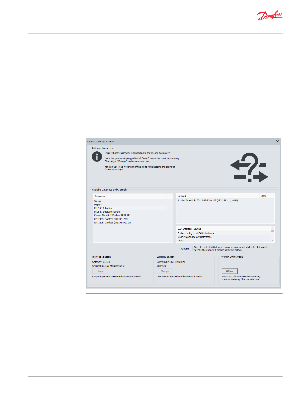
The Service Tool gateway needs to be changed to "PLUS+1®Interlink” using the menu Communications
> Gateway > PLUS+1 > Interlink > Enable.
In the list Devices double-click the device with the matching device EID. The device EID can be found on
the page M2M. The CS10 might have another node address if it was connected to another gateway
previously. If so, in the menu select Replace Missing ECU and former address will be replaced by the
current address of the device.
While in an M2M bridge, making an Interlink connection will break the M2M bridge functionality.
Overview
The keyswitch shutdown mode reduces the current consumption to a minimum and no functionality is
provided. Setting the Enable checkbox to true makes the device monitor the C1p05 pin and enter the
low power mode as soon as the pin voltage goes to GND. The Shutdown delay time parameter provides
the time by which entering the low power mode is delayed in seconds.
To have a remote connection to the CS10 via the internet, Proxy Enable flag must be set to true.
Disabling the option requires a power cycle or Device Restart.
The diagnostic address can be configured byapplying the appropriate value to the field Nodeaddress
and pressing the Save button. Changing this requires a power cycle or Device Restart.
©
Danfoss | November 2020 BC356772124151en-000102 | 7

Technical Information
PLUS+1® CS10 Wireless Gateway
Configuration
All device settings can be reset to their default values by using the Reset device button or by connecting
the C1p06 input to supply voltage for at least 10 seconds. Leave this pin open If resetting the device by
C1p06 is not intended.
Pressing the Device Restart button reboots the application and can be used as an alternative for a power
cycle.
Station mode
1. Go to the WiFi Configuration page and set “Station mode” as Operation mode.
2. If Autoenable is selected, the selected mode will be enabled once the device is powered.
3. Enter the SSID and Password of the network to be connected to.
4. If Autoconnect is selected, once the device is powered it will automatically try to connect to the
configured network.
5. Select the appropriate Country code.
6. If DHCP mode is set to "DHCP diabled" adjust the following settings:
•
IP address and Network mask for the identification of the CS10 device,
•
Gateway address and Gateway metric for identifying the AP to connect to,
•
Primary DNS-server IPv4 addr and Secondary DNS-server IPv4 addr must be set to gather the
IP address of an URI.
When DHCP mode is set to “DHCP enabled” no further settings need to be done.
Using the Save button downloads the data to the device. The actual settings are shown in the section
Actual settings.
Using the Reset button applies a default set of standard parameters.
8 | © Danfoss | November 2020 BC356772124151en-000102

Technical Information
PLUS+1® CS10 Wireless Gateway
Configuration
On the WiFi Connection page, client status shows the connection status of the CS10 device.
Enable/Disable activates/deactivates the WiFi unit of the device, the actual status is indicated by the LED
WiFi enabled. When using the Connect button the device tries to connect to the access point defined in
the WiFi Connection.
The name of the network client is shown in the field SSID. The Mode field indicates if the connection has
been established. Link quality shows the quality of the connection when it’s established.
Connection IPv4 address shows the assigned network address.
The section AP list shows the networks available. Using the Scan button starts a scan for available
networks.
The number of available networks is shown in the field Number of access points, the first element to be
shown in the list can be selected with the Start index field.
For each available network the SSID, signal quality, signal level and the security type are provided.
©
Danfoss | November 2020 BC356772124151en-000102 | 9

Technical Information
PLUS+1® CS10 Wireless Gateway
Configuration
10 | © Danfoss | November 2020 BC356772124151en-000102

Technical Information
PLUS+1® CS10 Wireless Gateway
Configuration
Access point
1. Go to the WiFi Configuration page and set “Access point” as Operation mode
2. If Autoenable is set the automatically enable itself when the device is powered
3. Select SSID and Password for identifying the network
4. Select the appropriate Channel
5. Set the address of the access point to be created in in IPv4 address and Netmask
6. If DHCP enable is set all clients that connect as DHCP client automatically retrieve an address from
the range defined in the fields IPv4 start address and IPv4 end address for the time defined in the
field Lease time
7. Using the Save button downloads the data to the device. The actual settings are then shown in the
section Actual settings
Using the Reset button applies a set of default parameter.
©
Danfoss | November 2020 BC356772124151en-000102 | 11

Technical Information
PLUS+1® CS10 Wireless Gateway
Configuration
On the WiFi Connection page, the status of the configured access point is shown in the section AP
status.
Enable/Disable activates/deactivates the Access point unit of the device manually, the actual status is
indicated by the LED AP enabled.
A list of the devices connected to the access point is provided in the section Connected clients.
The number of clients is shown in the field Amount. In the field Index the device at this index in the list is
shown when applying the GoToIndex button. The MAC address and IPv4 address are then shown in the
corresponding fields.
12 | © Danfoss | November 2020 BC356772124151en-000102

Technical Information
PLUS+1® CS10 Wireless Gateway
Configuration
CAN
The CAN section provides the possibility to setup a set of messages to be received.
The desired baudrate for the CAN unit needs to be set in the field Baudrate.
When the baudrate has changed this setting activates after the next power cycle or by using the
DeviceRestart button on the Overview page.
For each signal to be received the ID, Indicator for extended ID (Ext ID) and Mask must be applied. The
option Protect leaves the latest received message at the output of the corresponding CAN receiver.
Pressing the Save button sends the applied configuration to the device.
Using the Reset button applies a set of default parameters.
When a corresponding message has been received its parameter appears in the fields Received ID,
Length and Data. The LED indicates if the message has been received during the previous second.
©
Danfoss | November 2020 BC356772124151en-000102 | 13

Technical Information
PLUS+1® CS10 Wireless Gateway
Configuration
M2M
The M2M Bridge establishes a connection that transmits CAN messages between CS10 devices using an
existing WiFi-connection between them. The two devices can be connected peer to peer where one
device is configured as an Access point, and the other one is configured to station mode (DHCP must be
disabled). Alternatively, both can be configured to station mode to connect to a router, in this case DHCP
needs to be enabled.
For a successful M2M configuration one device needs to be configured as a master, the other one as a
slave using the field Role.
For the slave only the Local Password must be applied which needs to match the Remote Password of
the master device. Due to its multipurpose meaning the local password can be found on the Overview
page.
For the master device the following settings must be applied. The operation mode can be set in the field
Remote EID mode. In auto-mode a connection to the first accessible Interlink-device to be found is
established while in manual mode a connection to the device with the Interlink EID to be set in the field
Remote EID is established. To connect to a device the remote password must be applied in the field
Remote Password where it must match the local password of the slave device. If the option Autoenable
is set, the M2M unit is automatically enabled when the device is powered. The set of messages to be
transferred to and from the connected device is defined in the sections Remote/Local filter
configuration . In the dropdown list above there are three options available where “Pass all messages”
let’s all messages pass through while “Block all messages” let’s no message pass through. The option
“Define messages” offers the opportunity to explicitly select up to 10 messages to be transmitted. If the
set of Filter/Mask is set to 0 for both all messages will pass the bridge. If the set of Filter/Mask is set to
0x80000000 for both the message is blocked. In the Output filter configuration section all outgoing
messages are defined, while in the Input filter configuration section all incoming messages are defined.
All these settings get applied to the device when pressing the button Save.
14 | © Danfoss | November 2020 BC356772124151en-000102

Technical Information
PLUS+1® CS10 Wireless Gateway
Configuration
The master device automatically starts to establish a connection as soon as it’s enabled. The current
status of the connection is shown under Status.
Using the Reset button applies a set of default parameters.
LEDs
There are four LEDs on every CS10 module: one blue, one white, one green, and one red. These are under
application software control of the primary processor.
©
Danfoss | November 2020 BC356772124151en-000102 | 15

Technical Information
PLUS+1® CS10 Wireless Gateway
Programming
Nonfunctional specifications
PLUS+1® compliance development
Applicable company software development standards must be adhered to. At time of initial
development Danfoss Power Solutions SW PDP v5.00 (70036901v5.00) is the adopted standard.
16 | © Danfoss | November 2020 BC356772124151en-000102

C
Technical Information
PLUS+1® CS10 Wireless Gateway
Product ratings
Environmental testing criteria
Specifications
Operating temperature (ambient)
Storage temperature
IP rating (with mating connector attached)
– 30°C to 70°C
– 40°C to 85°C
IP 67
Caution
With DEUTSCH DTM06-6S or equivalent mating connector attached
Operating input voltage
Operating input current
Power consumption
Shutdown current
Vibration
EMI/RFI rating
Weight
6 to 36 VDC
100 mA at 24 VDC
2.4 W
1 mA max at 24 VDC
IEC 60068-2-64
100 V/M
110 g
Chemical environment
Description Applicable standard Comment
Chemical resistance
ISO 16750-5
Mechanical environment
Description Applicable standard Comment
Vibration
Bump
Shock
Free fall
IEC 60068-2-64 test Fh
IEC 60068-2-29 test Eb
IEC 60068-2-27 Ea
IEC 60068-2-32 Ed
Electrical/electromagnetic
Description Applicable standard Comment
EMC emission
EMC immunity
Electrostatic discharge
Auto electrical transients
Short circuit protection
Reversed polarity protection
Reversed polarity logic power
Reversed polarity battery power
©
Danfoss | November 2020 BC356772124151en-000102 | 17
ISO 13766
ISO 13766
EN 61000-4-2, SAE J1113-13
ISO 7637-2 & -3
504H0027
504H0027

C
C
Technical Information
PLUS+1® CS10 Wireless Gateway
Product ratings
Power
Module supply voltage/maximum current ratings
CS10 modules are designed to operate with a nominal 6 to 36 Vdc power supply.
The modules will survive with full functionality if the supply voltage remains below 36 Vdc.
Specifications
Description Units Minimum Maximum Comment
Allowed voltage at pin V 36
Allowed module current A 0.3
Caution
PCB damage may occur.
To prevent damage to the module all module power supply + pins must be connected to the vehicle
power supply to support advertised module maximum output current capacity. DO NOT use module
power supply + pins to supply power to other modules on a machine.
Modules housing
CS10 module housing features are ultrasonically welded together with an assembly that is tamper-proof.
Once assembled at the factory, the housing cannot be opened for service.
Caution
Warranty will be voided if device is opened.
Device is not field serviceable. Do not open the device.
18 | © Danfoss | November 2020 BC356772124151en-000102

144.00 [5.67]
50.80 [2.00]
45.00 [1.78]
30.00 [0.12]
0.50 [0.02]
120.10 [4.73]
79.50 [3.13]
4
5
6
3
2
1
Technical Information
PLUS+1® CS10 Wireless Gateway
Product installation and start-up
Dimensions
Mounting dimensions (mm [in] and pin assignments
Connector
Hot plugging
Mounting
CS10modules use DEUTSCH connectors. The approved mating connector is the DEUTSCH DTM06-6S
Plug. Danfoss assembles mating connector kits, referred to as a bag assembly.
Pin connector
Pin Function Pin Function
1 GND 4 CAN Low
2 Power 5 Key Switch
3 CAN High 6 CAN Shield / Pairing
Machine power should be off when connecting CS10 modules to mating connectors.
Care must be taken to insure that the module connector is positioned so that moisture drains away from
the connector.
Provide strain relief for mating connector wires.
Fasteners
Recommended outer diameter (OD)
M6
©
Danfoss | November 2020 BC356772124151en-000102 | 19

Technical Information
PLUS+1® CS10 Wireless Gateway
Product installation and start-up
Grounding
Proper operation of any electronic control system requires that all control modules including displays,
microcontrollers and expansion modules be connected to a common ground. A dedicated ground wire
of appropriate size connected to the machine battery is recommended.
20 | © Danfoss | November 2020 BC356772124151en-000102

W
C
Technical Information
PLUS+1® CS10 Wireless Gateway
Product installation and start-up
Machine wiring guidelines
Warning
Unintended movement of the machine or mechanism may cause injury to the technician or bystanders.
Improperly protected power input lines against over current conditions may cause damage to the
hardware. Properly protect all power input lines against over-current conditions. To protect against
unintended movement, secure the machine.
Caution
Unused pins on mating connectors may cause intermittent product performance or premature failure.
Plug all pins on mating connectors.
•
Protect wires from mechanical abuse, run wires in flexible metal or plastic conduits.
•
Use 85˚ C (185˚ F) wire with abrasion resistant insulation and 105˚ C (221˚ F) wire should be
considered near hot surfaces.
•
Use a wire size that is appropriate for the module connector.
•
Separate high current wires such as solenoids, lights, alternators or fuel pumps from sensor and other
noise-sensitive input wires.
•
Run wires along the inside of, or close to, metal machine surfaces where possible, this simulates a
shield which will minimize the effects of EMI/RFI radiation.
•
Do not run wires near sharp metal corners, consider running wires through a grommet when
rounding a corner.
•
Do not run wires near hot machine members.
•
Provide strain relief for all wires.
•
Avoid running wires near moving or vibrating components.
•
Avoid long, unsupported wire spans.
•
Ground electronic modules to a dedicated conductor of sufficient size that is connected to the
battery (-).
•
Power the sensors and valve drive circuits by their dedicated wired power sources and ground
returns.
•
Twist sensor lines about one turn every 10 cm (4 in).
•
Use wire harness anchors that will allow wires to float with respect to the machine rather than rigid
anchors.
Machine welding guidelines
The following is recommended when welding on a machine equipped with electronic components:
•
Turn the engine off.
•
Remove electronic components from the machine before any arc welding.
•
Disconnect the negative battery cable from the battery.
•
Do not use electrical components to ground the welder.
•
Clamp the ground cable for the welder to the component that will be welded as close as possible to
the weld.
©
Danfoss | November 2020 BC356772124151en-000102 | 21

Danfoss
Power Solutions GmbH & Co. OHG
Krokamp 35
D-24539 Neumünster, Germany
Phone: +49 4321 871 0
Danfoss
Power Solutions ApS
Nordborgvej 81
DK-6430 Nordborg, Denmark
Phone: +45 7488 2222
Danfoss
Power Solutions (US) Company
2800 East 13th Street
Ames, IA 50010, USA
Phone: +1 515 239 6000
Danfoss
Power Solutions Trading
(Shanghai) Co., Ltd.
Building #22, No. 1000 Jin Hai Rd
Jin Qiao, Pudong New District
Shanghai, China 201206
Phone: +86 21 2080 6201
Products we offer:
Hydro-Gear
www.hydro-gear.com
Daikin-Sauer-Danfoss
www.daikin-sauer-danfoss.com
Cartridge valves
•
DCV directional control
•
valves
Electric converters
•
Electric machines
•
Electric motors
•
Gear motors
•
Gear pumps
•
Hydraulic integrated
•
circuits (HICs)
Hydrostatic motors
•
Hydrostatic pumps
•
Orbital motors
•
PLUS+1® controllers
•
PLUS+1® displays
•
PLUS+1® joysticks and
•
pedals
PLUS+1® operator
•
interfaces
PLUS+1® sensors
•
PLUS+1® software
•
PLUS+1® software services,
•
support and training
Position controls and
•
sensors
PVG proportional valves
•
Steering components and
•
systems
Telematics
•
Danfoss Power Solutions is a global manufacturer and supplier of high-quality hydraulic and
electric components. We specialize in providing state-of-the-art technology and solutions
that excel in the harsh operating conditions of the mobile off-highway market as well as the
marine sector. Building on our extensive applications expertise, we work closely with you to
ensure exceptional performance for a broad range of applications. We help you and other
customers around the world speed up system development, reduce costs and bring vehicles
and vessels to market faster.
Danfoss Power Solutions – your strongest partner in mobile hydraulics and mobile
electrification.
Go to www.danfoss.com for further product information.
We offer you expert worldwide support for ensuring the best possible solutions for
outstanding performance. And with an extensive network of Global Service Partners, we also
provide you with comprehensive global service for all of our components.
Local address:
Danfoss can accept no responsibility for possible errors in catalogues, brochures and other printed material. Danfoss reserves the right to alter its products without notice. This also applies to products
already on order provided that such alterations can be made without subsequent changes being necessary in specifications already agreed.
All trademarks in this material are property of the respective companies. Danfoss and the Danfoss logotype are trademarks of Danfoss A/S. All rights reserved.
©
Danfoss | November 2020 BC356772124151en-000102
 Loading...