

Page 1
Data Sheet
Pressure switch
Type CS
For air compressors and water boosters
CS pressure switches have a built-in pressure
operated, three-pole switch. The contact
position of which depends on the pressure in
the connector and the range setting and
adjustable dierential.
The pressure switches are tted with a manual
switch that will lock the contact system in the
open position independently of the pressure in
the system. Pressure switches with relief valve is
used in compressed air systems where pressure
relief on the compressor piston before start is
required.
The CS is suited for automatic start and stop of
air compressors and water boosters.
Features:
• Pressure ranges 2 – 20 bar
• Pressure connection G ½ or G ¼
• Contact system 3-pole (TPST) as standard
available also as an accessory
• Adjustable dierential
• Relief valve as accessory
• Manual switch to lock the contact system
• Enclosure IP43 or IP55
• Special versions with pressure connection
made of polyacetal suitable in drinking water
applications
AI239086444789en-000701
Page 2
12345678910111213141516171819202122232425
Danfoss
31E58
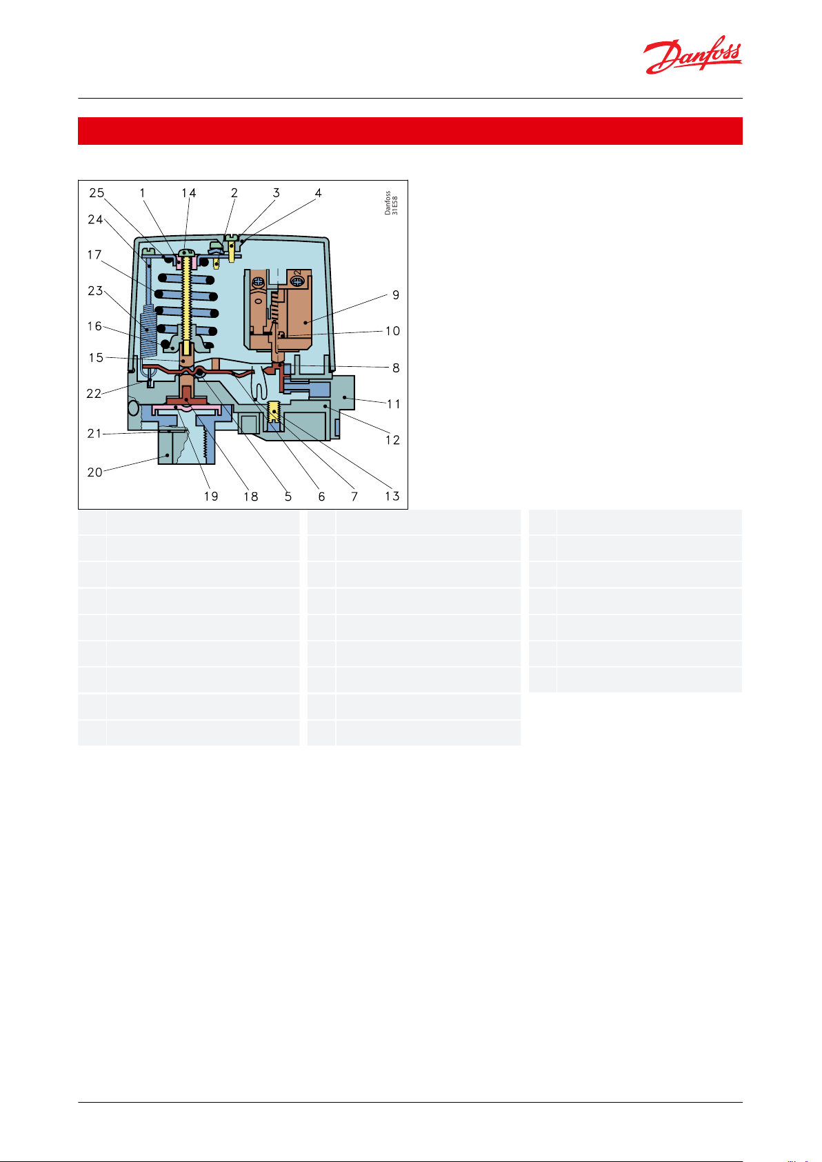
Slide ring
Earth screw
Cover screw
Cover
Spindle
Toggle arm
Snap spring
Snap arm
Switch housing assy
Self-tapping screw
Manual switch
Base
Grubscrew
Stop pressure screw
Pressure pad
Spring retainer
Compression spring
Pressure shoe
Diaphragm
Flange, G ¼ or G ½
Cap
Dierential arm
Tension spring
Dierential pressure screw
Bracket
Pressure switch, Type CS
Function
Figure 1: Design and function
The pressure switch is built up of the following main elements: connector, diaphragm, snap system, main spring,
dierential spring and a 3-pole or one-pole contact system. The stop pressure must be set on the main spring and
the dierence between start and stop pressures on the dierential spring.
Pressure from the controlled system is led, via the connector, to the diaphragm. The diaphragm converts this
pressure to a mechanical movement which is transferred by the snap system to the contact system. In this way, the
contact system starts or stops a compressor/pump.
© Danfoss | Climate Solutions | 2021.03 AI239086444789en-000701 | 2
Page 3
A
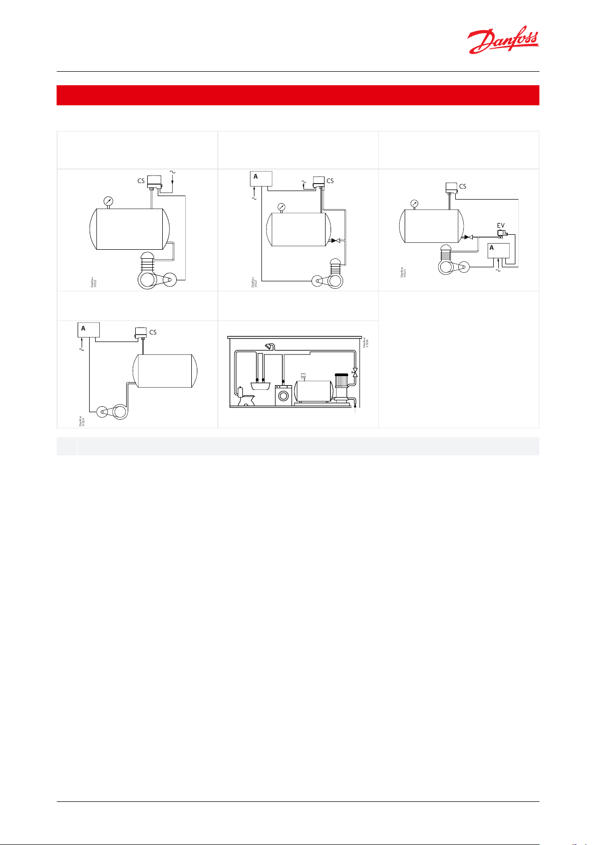
Example 1
Control of an air compressor with a CS pressure
switch.
Example 2
Control of a compressor with a CS pressure switch
tted with pressure relief valve. Note the check valve
between pressure relief line and reservoir.
Example 3
Control of an air compressor with a CS. An EV210B 3B
solenoid valve is recommended where there is need
for especially fast pressure relief.
CS
Danfoss
31E22
CS
A
Danfoss
31E27
CS
A
Example 4
Control of a centrifugal pump with a CS, via an
automatic star-delta switch, motor starter, or similar.
Example 5
Pressure boosting system for domestic circuits. A type
CS switch is used to start/stop the pump.
CS
A
Danfoss
31E56
Motor starter or automatic start-delta switch
Pressure switch, Type CS
Application
Table 1: Application examples
© Danfoss | Climate Solutions | 2021.03 AI239086444789en-000701 | 3
Page 4

Electrical life on rated load
100.000 operations
Mechanical life
1.000.000 operations
Ambient temperature
-20 – 70 °C
Temperature of medium
(1)
Water
0 – 70 °C
Air
-20 – 70 °C
Vibration-proof
0 – 1000 Hz at 4g
Resonance frequency,
see Figure 2
Direction A-B
341 Hz
Direction C-D
332 Hz
Direction E-F
488 Hz
Diaphragm material
Hytrel
Pressure connector
Special
Polyacetal, G ½
Others
Silumin, G ¼ or G ½
Pressure relief valve (capacity)
2000 cm3 from 10 – 1 bar in 18.8 sec.
Grade of enclosure to IEC 529
IP43 or IP55
Danfoss
U31E34
Contact load
IeU
e
AC-3
12 A
220 – 415 V
AC-3
9 A
600 V
DC-13/14
2 A
220 V (3 contacts in series)
Wire dimension
solid / stranded
0.7 – 2.5 mm
2
exible,
with / without ferrules
0.75 – 2.5 mm
2
exible,
with ferrules
0.5 – 1.5 mm
2
Tightening torque
max. 1.2 Nm
Rated impulse voltage
4 kV
Pollution degree
3
Short circuit protection, fuse
25 A
Insulation
600 V
IP-index
IP43 or IP55
Pressure switch, Type CS
Product specication
Technical data
Table 2: Specications
(1)
(1)
For water and seawater, max. 80 °C
For water and seawater, max. 80 °C
Figure 2: Resonance frequency
Table 3: Contact load
Table 4: Properties according to EN 60947
© Danfoss | Climate Solutions | 2021.03 AI239086444789en-000701 | 4
Page 5

Danfoss
31E43
12Stop pressure screw
Dierential screw
Danfoss
31E47
Turns of
screw
Pressure switch, Type CS
Setting
Figure 3: Adjustment
All standard versions of CS pressure switches are preset and supplied with springs under minimum compression.
1.
Turn the stop pressure screw (1) the given number of times towards + (high stop pressure), see Figure 4: Stop
pressure graph.
2.
Turn the dierential screw (2) the given number of times towards + (max. dierential), see Dierential pressure
nomograms.
3.
Start the plant and let it run until the required stop pressure is reached.
4.
Turn the stop pressure screw (1) towards minus (lower stop pressure) until the plant stops.
5.
Reduce the pressure to the required start pressure.
6.
Turn the dierential screw (2) towards minus (smaller dierential) until the plant starts.
7.
Check that the plant stops and starts at the required pressures.
NOTE:
If the dierential is set at a value greater than the stop pressure the plant cannot start. If this is the case, set the
dierential at a smaller value (towards minus).
Figure 4: Stop pressure graph
Example:
A compressor is to be regulated by a CS pressure switch. The start pressure is 3.5 bar, and the stop pressure 5 bar.
The choice should be a CS with a range of 2 – 6 bar.
1.
Turn the stop pressure screw (1) about 12 times. See Figure 3: Adjustment.
2.
Turn the dierential screw (2) about 4.5 times. See Figure 8: CS 2–6 [bar]. Take a straight line from 5 bar stop
pressure on the nomogram to the dierential, 1.5 bar and read o the number of turns, i.e. 4.5.
© Danfoss | Climate Solutions | 2021.03 AI239086444789en-000701 | 5
Page 6

Danfoss
31E52
Danfoss
31E51
d > 8.5 mm – 1
d ≤ 8.5 mm – 2
031E0293
Danfoss
31E73
Pressure switch, Type CS
Take a straight line from 5 bar stop pressure on the nomogram to the dierential, 1.5 bar and read o the number of
turns, i.e. 4.5.
Installation
Recommended orientation
The pressure switches will operate regardless of their orientation. However, to meet the enclosure requirements of
IP43 and IP55, they must be mounted vertically with the connection downwards. The CS pressure switches are selfsupporting (on the connection).
Fitting a pressure relief valve:
1.
Remove the blanking plug
2.
Fit the pressure relief valve
3.
Fit the plastoform screw
Figure 5: Installation
Figure 6: Installation
Fitting screwed cable entries
The accessory bag contains two sets of metal gaskets each with dierent internal diameters. These will give a
sucient cord relief if used correctly with the cable diameter concerned.
Drain hole
If because of large temperature variations there is a risk of condensate forming in the pressure switch, a screwdriver
can be used to make a drain hole in the enclosure.
Figure 7: Drain hole
© Danfoss | Climate Solutions | 2021.03 AI239086444789en-000701 | 6
Page 7

Danfoss
31E53
Stop pressure
No. of turns
on Δp screw
CS 2–6 [bar]
Differential
Danfoss
31E54
Stop pressure
CS 4–12 [bar]
Differential
No. of turns
on Δp screw
Danfoss
31E55
Stop pressure
CS 7–20 [bar]
Differential
No. of turns
on Δp screw
Danfoss
31E61
Danfoss
31E62
Danfoss
31E63
Danfoss
31E49
IeU
e
AC-3
12 A
220 V – 415 V
9 A
600 V
DC-13 / 14
2 A
220 V (3 contacts in series)
Pressure switch, Type CS
Dierential pressure nomograms
Figure 8: CS 2–6 [bar]
Figure 9: CS 4–12 [bar]
Dimensions [mm] and weights [kg]
Figure 11: Dimensions [mm]
Figure 10: CS 7–20 [bar]
Weight approx. 0.5 kg
Mains connection
Figure 12: 3-pole AC load
Table 5: Contact load
© Danfoss | Climate Solutions | 2021.03 AI239086444789en-000701 | 7
Figure 13: 1-pole AC load
Figure 14: 1-pole DC load
Page 8

Stop pressure p
e
[bar]
Min. dierential
Δp [bar]
Max. dierential
Δp [bar]
Max. test
pressure p
e
[bar]
Grade of
enclosure
Pressure
connection
Code no.
Type
2 – 6
0.72 – 1.0
1.0 – 2.010IP43
G ¼
031E020266
1-pole
2 – 6
0.72 – 1.0
1.0 – 2.010IP43
G ¼
031E020066
3-pole
2 – 6
0.72 – 1.0
1.0 – 2.010IP55
G ¼
031E020566
3-pole
2 – 6
0.72 – 1.0
1.0 – 2.010IP43
G ½
031E021066
3-pole
2 – 6
0.72 – 1.0
1.0 – 2.010IP55
G ½
031E021566
(1)
3-pole
4 – 12
1 – 1.5
2.0 – 4.020IP43
G ¼
031E022066
3-pole
4 – 12
1 – 1.5
2.0 – 4.020IP55
G ¼
031E022566
(1)
3-pole
4 – 12
1 – 1.5
2.0 – 4.020IP43
G ½
031E023066
3-pole
4 – 12
1 – 1.5
2.0 – 4.020IP55
G ½
031E023566
(1)
3-pole
7 – 20
2 – 3.5
3.5 – 7.032IP43
G ¼
031E024066
3-pole
7 – 20
2 – 3.5
3.5 – 7.032IP55
G ¼
031E024566
3-pole
7 – 20
2 – 3.5
3.5 – 7.032IP43
G ½
031E025066
3-pole
7 – 20
2 – 3.5
3.5 – 7.032IP55
G ½
031E025566
(1)
3–pole
Stop pressure p
e
[bar]
Min. dierential
Δp [bar]
Max. dierential
Δp [bar]
Max. test
pressure p
e
[bar]
Grade of
enclosure
Pressure
connection
Code no.
Type
2 – 6
0.72 – 1.0
1.0 – 2.010IP43
G ½
031E101066
3-pole
4 – 12
1 – 1.5
2.0 – 4.020IP43
G ½
031E101266
3-pole
7 – 20
2 – 3.5
3.5 – 7.032IP43
G ½
031E101466
3–pole
Description
Code no.
Three pole contact system (TPST)
031E029166
Pressure relief valve, incl.
xing screw (for 6 mm pipe/hose)
031E029866
Pressure relief valve, incl.
xing screw (for 1/4 in. pipe/hose)
031E029766
Two Pg 16 screwed cable entries with gaskets (cable diam. 6.5 – 15 mm)
031E029366
Nipple with 7/16-20 UNF and M10 x 1 int.
031E029666
File name
Document type
Document topic
Approval authority
BK_W_0862_01_2108
Food and Health - Performance
Certicate
-
PZH
RU C-DK.БЛ08.В.00063_18
Electrical - Safety
Certicate
EMC/LVE
EAC
UA.1O146.D.00075-19
UA Declaration
EMCD/LVD
LLC CDC EURO TYSK
060-9650.AC
EU Declaration
LVD/RoHS
Danfoss
Pressure switch, Type CS
Ordering
Table 6: Standard pressure switch type CS
(1)
(1)
Preferred versions
Preferred versions
Table 7: Special versions with Polyacetal pressure connection - suitable for drinking water
Accessories and spare parts
Table 8: Accessories and spare parts
Certicates, declarations, and approvals
The list contains all certicates, declarations, and approvals for this product type. Individual code number may have
some or all of these approvals, and certain local approvals may not appear on the list.
Some approvals may change over time. You can check the most current status at danfoss.com or contact your local
Danfoss representative if you have any questions.
Table 9: Certicates, declarations, and approvals
© Danfoss | Climate Solutions | 2021.03 AI239086444789en-000701 | 8
Page 9

Online support
Danfoss oers a wide range of support along with our products, including digital product information, software,
mobile apps, and expert guidance. See the possibilities below.
The Danfoss Product Store
The Danfoss Product Store is your one-stop shop for everything product related—no matter where
you are in the world or what area of the cooling industry you work in. Get quick access to essential
information like product specs, code numbers, technical documentation, certications, accessories,
and more.
Start browsing at store.danfoss.com.
Find technical documentation
Find the technical documentation you need to get your project up and running. Get direct access to
our ocial collection of data sheets, certicates and declarations, manuals and guides, 3D models
and drawings, case stories, brochures, and much more.
Start searching now at www.danfoss.com/en/service-and-support/documentation.
Danfoss Learning
Danfoss Learning is a free online learning platform. It features courses and materials specically
designed to help engineers, installers, service technicians, and wholesalers better understand the
products, applications, industry topics, and trends that will help you do your job better.
Create your Danfoss Learning account for free at www.danfoss.com/en/service-and-support/learning.
Get local information and support
Local Danfoss websites are the main sources for help and information about our company and
products. Find product availability, get the latest regional news, or connect with a nearby expert—all
in your own language.
Find your local Danfoss website here: www.danfoss.com/en/choose-region.
Danfoss can accept no responsibility for possible errors in catalogues, brochures and other printed material. Danfoss reserves the right to alter its
products without notice. This also applies to products already on order provided that such alterations can be made without subsequential
changes being necessary in specications already agreed. All trademarks in this material are property of the respective companies. Danfoss and
the Danfoss logotype are trademarks of Danfoss A/S. All rights reserved.
© Danfoss | Climate Solutions | 2021.03 AI239086444789en-000701 | 9
 Loading...