

Page 1
Creep
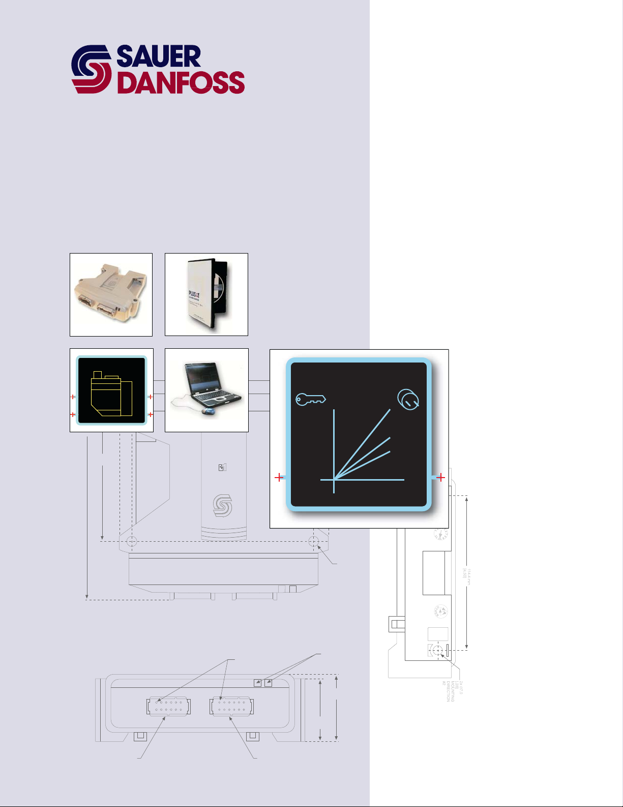
PLUS+1™ GUIDE
Software
Creep Plug-in
GUIDE Programming
User Manual
142.0 mm
[5.59]
VALV E
97.0 mm
[3.82]
158.2 mm
6.23
144.5 mm
5.69
Creep
2x 25.2 mm
[1.0]
2x ∅7.0
[.28]
MOUNTING
DIRECTION
#2
CONNECTOR MATES
WITH DEUTCH
CONNECTOR #DTM-06-125A
LED INDICATO R
47.1 mm
[1.85]
LIGHTS
51.6 mm
[2.03]
PIN #1
INDICATED
1
12
6
7
1
12
6
7
CONNECTOR MATES
WITH DEUTCH
CONNECTOR #DTM-06-125A
Page 2

Creep Plug-in GUIDE Programming
User Manual
About this Manual
Organization
and Headings
To help you quickly find information in this manual, the material is divided into sections,
topics, subtopics, and details, with descriptive headings set in red type. Section titles
appear at the top of every page in large red type. Topic headings appear in the left-hand
column in bold red type. Subtopic headings appear above the body text in bold red
type and detail headings in italic red type.
References (example: See Topic xyz, page XX) are also formatted in red italic type. In
Portable Document Format (PDF) files, these references are hyperlinks that jump to the
corresponding document pages.
Tables, Illustrations, and
Complementary
Information
Tables, illustrations, and graphics in this manual are identified by titles set in blue italic
type above each item. Complementary information such as notes, captions, and drawing
annotations are also set in blue type.
Special Text Formatting Controls and indicators are set in bold black type.
Black italic type is used in the text to emphasize important information, or to set off words
and terms that are used in an unconventional manner or alternative context.
Table of Contents
A Table of Contents (TOC) appears on the next page. In the PDF version of this document,
the TOC entries are hyperlinked.
Revision history
Revision Date Comment
Rev AA January 2009 For software release 1.xx.
©2009 Sauer-Danfoss. All rights reserved.
Sauer-Danfoss accepts no responsibility for possible errors in catalogs, brochures and other printed material.
Sauer-Danfoss reserves the right to alter its products without prior notice. This also applies to products already
ordered provided that such alterations can be made without affecting agreed specifications.
All trademarks in this material are properties of their respective owners.
PLUS+1, GUIDE, and Sauer-Danfoss are trademarks of the Sauer-Danfoss Group. The PLUS+1 GUIDE, PLUS+1
2
Compliant, and Sauer-Danfoss logotypes are trademarks of the Sauer-Danfoss Group.
11059500 · Rev AA · January 2009
Page 3

Creep Plug-in GUIDE Programming
User Manual
Contents
Introduction ...................................................................................................................................................... 4
Page Symbols ........................................................................................................................................... 5
Creep Plug-in Page ......................................................................................................................................... 6
Input and Output Signals ..................................................................................................................... 7
Creep_Params Page................................................................................................................................ 8
About the Creep Plug-in............................................................................................................... 9
11059500 · Rev AA · January 2009
3
Page 4

Creep Plug-in GUIDE Programming
User Manual
Introduction
This manual documents the Creep plug-in.
The Creep plug-in receives inputs that turn it on and off. The Creep plug-in outputs either
a value of 100.00% or a lower, user-set value.
An application typically multiplies its input commands by the output of the Creep plug-in.
The Creep plug-in is usually turned on and off by an operator.
When the Creep plug-in turns on, its output ramps down from 100.00% to a lower, userset value.
Multiplying input commands by less than 100.00% produces scaled down commands that:
• Give the machine a lower top speed.
• Cause input changes (typically coming from a joystick) to produce smaller output
command changes, giving the operator better low-speed control.
When the Creep plug-in turns off, its output ramps up to 100.00%.
Multiplying input commands by 100.00% leaves output commands unchanged.
The Creep plug-in is a variant of the Maximum Command Scale type of plug-ins. The
Creep plug-in installs in a MaxCmdScale socket page.
4
11059500 · Rev AA · January 2009
Page 5

Page Symbols
Creep Plug-in GUIDE Programming
User Manual
Introduction
Slash—Page can be entered
No slash—Page locked; cannot be entered
Plug—Plug-in page
Key—Page keyed to application hardware
Page symbols indicate page properties:
• Slash—The page is unlocked. The page can be entered and its contents viewed and
changed.
• No slash—The page is locked and cannot be entered.
• Plug—The page contains a plug-in. A plug-in is software that extends the
functionality of an application.
• Key—An application that contains this page can only download to similarly keyed
application hardware.
11059500 · Rev AA · January 2009
5
Page 6

Creep Plug-in GUIDE Programming
User Manual
Creep Plug-in Page
Path: Creep
T = Set plug-in defaults
1
2
T/F = Plug-in on/off (operator)
Plug-in on = 5000 (50.00%)/Plug-in off = 10000 (100.00%)*
T = Plug-in off (fault)—overrides Creep_Req signal
The Creep plug-in outputs a Creep% value.
An application typically multiplies its input commands by the Creep% output to produce
scaled-down output commands.
With typical default values, when an operator turns the:
• Creep plug-in on, its Creep% output ramps down to 5000 (50.00%).
Multiplying input commands by 50.00% scales down output commands by 50.00%.
• Creep plug-in off, its Creep% output ramps up to 10000 (100.00%).
Multiplying input commands by 100.00% leaves output commands unchanged.
Creep Plug-in
Callout Item Description
1 Creep_Params page Contains non-volatile memory (EE) components whose output signals configure the Creep plug-in.
2 Creep page Outputs a Creep% value. An application typically multiplies its input commands by this value to produce
scaled-down output commands.
With typical default values, when the Creep plug-in:
– Turns on (B_Creep_Req signal = T), its Creep% output ramps down from 10000 (100.00%) to 5000
(50.00%).
Multiplying by 50.00% scales down output commands by 50.00%.
– Turns off (B_Creep_Req signal = F), its Creep% output ramps up to 10000 (100.00%).
Multiplying by 100.00% leaves output commands unchanged.
The B_Disable signal = T turns off the Creep plug-in, even if the B_Creep_Req signal = T.
*Typical
6
11059500 · Rev AA · January 2009
Page 7

Creep Plug-in GUIDE Programming
User Manual
Creep Plug-in Page
Input and Output Signals
Plug-in Input Signals
Bus/Signal Type Range Description
Signal bus —— —— Inputs the following signals to the plug-in.
B_SetDefaults
signal
B_Creep_Req
signal
B_Disable
signal
BOOL —— T = Apply default values to the plug-in.
BOOL —— T = Turn the plug-in on.
F = Turn the plug-in off.
Typically switched T/F by an operator.
BOOL —— T= Turn the plug-in off.
Typically set by a fault; overrides the B_Creep_Req signal.
Plug-in Output Signals
Bus/Signal Type Range Description
Diag bus —— —— Outputs signals that report the status of the plug-in.
Status
signal
Param
bus
B_Creep_Enable BOOL —— T = Plug-in enabled—Input signals can turn the plug-in on and off.
Creep_Pct2 U16 10000–5000 When the plug-in is turned on, the Creep% value = Creep_Pct2 value.
Creep_Ramp_mS U16 0–5000 Ramp time for the Creep% output to smoothly change between 10000 (100.00%) and the
Output
signal
U16 —— Bitwise report on the status of the plug-in.
0x0000 = OK.
0x8008 = Invalid setup.
—— —— Outputs configuration values set in the Creep_Params page.
F = Plug-in disabled—Input signals cannot turn the plug-in on.
An application multiplies the Creep% value by its input commands to produce scaled-down
output commands.
10000 = 100.00%
CreepPct2 value.
1000 = 1000 ms
U16 5000–10000 The Creep% value.
An application typically multiplies the Creep% value by its input commands to produce
scaled-down output commands.
When the plug-in turns on, the Creep% value = the CreepPct2 value.
When the plug-in turns off, the Creep% value = 10000 (100.00%).
10000 = 100.00%
11059500 · Rev AA · January 2009
7
Page 8

Creep_Params Page
Creep Plug-in GUIDE Programming
User Manual
Creep Plug-in Page
Path: Creep ! Creep_Params
T = Apply IN values
1
2
3
The Creep_Params page contains non-volatile memory (EE components) whose output
signals configure the Creep plug-in.
Creep_Params Page
Callout Item Description
1 EE_Creep_Enable
EE value
2 EE_Creep_Pct2
EE value
3 EE_Creep_Ramp_mS
EE value
Outputs the B_Creep_Enable signal.
T = Plug-in enabled—Input signals can turn the plug-in on and off.
F = Plug-in disabled—The plug-in is off. Input signals cannot turn the plug-in on.
Outputs the Creep_Pct2 signal.
When the plug-in turns on, it outputs this value.
An application typically multiplies this value by its input commands to produce scaled-down output
commands.
Range: 5000–10000 (10000 = 100.00%)
Outputs the Creep_Ramp_mS signal.
This signal sets the ramp time for the Creep% output to smoothly change between 10000 (100.00%) and
the Creep_Pct2 value.
A Time Ramp function block inside the locked Creep page outputs this ramp.
For more about the Time_Ramp function block, refer to the PLUS+1 GUIDE Basic Function Blocks Library
User Manual (Sauer-Danfoss part 10103409).
Range: 0–10000 (1000 =1000 ms)
8
11059500 · Rev AA · January 2009
Page 9

Creep Plug-in GUIDE Programming
User Manual
Creep Plug-in Page
About the Creep Plug-in
10000
9000
8000
Output Command (10000 = 100.00%)
7000
6000
5000
4000
3000
Output Command—Creep off/Creep% = 10000 (100.00%)
Output Command—Creep on/Creep% = 5000 (50.00%)
2000
1000
0
0
1000
2000 3000
Input: Pump Command (10000 = 100.00%)
Input Command (10000 = 100.00%)
4000
5000
6000
7000 8000
9000
10000
In this example, when the operator:
• Turns the Creep plug-in on, the Creep% output ramps down to 5000 (50.00%).
• Turns the Creep plug-in off, the Creep% output ramps up to 10000 (100.00%).
An application typically multiplies its input commands by the Creep% value to produce
scaled-down output commands.
In this example, when the operator:
• Turns the Creep plug-in on, the plug-in scales down output commands by 50.00%.
− A 10000 (100.00%) input command scales down to a 5000 (50.00%) output
command.
− A 5000 (50.00%) input command scales down to a 2500 (25.00%) output
command.
• Turns the Creep plug-in off, the Creep% does not scale down output commands.
11059500 · Rev AA · January 2009
9
Page 10

OUR PRODUCTS
Hydrostatic transmissions
Hydraulic power steering
Electric power steering
Electrohydraulic power steering
Closed and open circuit axial piston
pumps and motors
Gear pumps and motors
Bent axis motors
Orbital motors
Transit mixer drives
Planetary compact gears
Proportional valves
Sauer-Danfoss Hydraulic Power Systems
- Market Leaders Worldwide
Sauer-Danfoss is a comprehensive supplier providing complete
systems to the global mobile market.
Sauer-Danfoss serves markets such as agriculture, construction, road
building, material handling, municipal, forestry, turf care, and many
others.
We offer our customers optimum solutions for their needs and
develop new products and systems in close cooperation and
partnership with them.
Sauer-Danfoss specializes in integrating a full range of system
components to provide vehicle designers with the most advanced
total system design.
Sauer-Danfoss provides comprehensive worldwide service for its products
through an extensive network of Global Service Partners
strategically located in all parts of the world.
Directional spool valves
Cartridge valves
Hydraulic integrated circuits
Hydrostatic transaxles
Integrated systems
Fan drive systems
Electrohydraulics
Microcontrollers and software
Electric motors and inverters
Joysticks and control handles
Displays
Sensors
Local address:
Sauer-Danfoss Inc.
3500 Annapolis Lane North
Minneapolis, MN 55447, USA
Phone: +1 763 509-2000
Fax: +1 763 559-5769
Sauer-Danfoss (US) Company
2800 East 13th Street
Ames, IA 50010, USA
Phone: +1 515 239-6000
Fax: +1 515 239-6618
Sauer-Danfoss ApS
DK-6430 Nordborg, Denmark
Phone: +45 7488 4444
Fax: +45 7488 4400
Sauer-Danfoss GmbH & Co. OHG
Postfach 2460, D-24531 Neumünster
Krokamp 35, D-24539 Neumünster, Germany
Phone: +49 4321 871-0
Fax: +49 4321 871 122
Sauer-Danfoss-Daikin LTD
Sannomiya Grand Bldg. 8F
2-2-21 Isogami-dori, Chuo-ku
Kobe, Hyogo 651-0086, Japan
Phone: +81 78 231 5001
Fax: +81 78 231 5004
11059500 · Rev AA · January 2009
www.sauer-danfoss.com
 Loading...