

Page 1
CRCT230HCW1
Electronic Heat / Cool thermostat with
auto-changeover based on water temperature
GB
Installation Instructions
User Instructions
Page 2

GB
Index
Installation Instructions 3-8
User Instructions 9
Installation Instructions
2
Page 3
3
Installation Instructions
Please note
This product should only be installed by a suitably qualifi ed
electrician or heating installer. The installation must comply
with local Building Regulations and wiring Regulations,
including any competent person requirements that may exist
GB
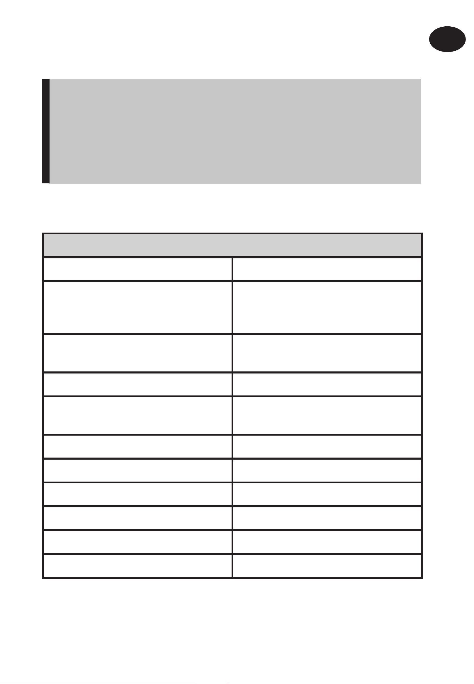
Product Specifi cation
Thermostat features
Temperature range, heating 5-30°C
Water changeover temp
- Cool to Heat
- Heat to Cool
Thermostat off /auto & fan on
selector
Power supply 230 Vac ± 15%, 50/60Hz
> 30°C
< 16°C
O
Installation Instructions
Relay outputs, heat/cool & fan 2 x SPST, 3(1)A, 10-230 Vac, Type
1B
Dimensions (mm) 110 wide x 90 high x 40 high
Design standard EN60730-2-9
Rated impulse voltage 2.5Kv
Ball hardness test 75°C
Control pollution situation Degree 2
Temperature accuracy ±1°C
Page 4
GB
Product overview
The thermostat is designed for use in systems equipped with fan
coils served by a 2-pipe central changeover system. The thermostat
controls the operation of a motorized valve which, during heating
periods, opens when heat is required and which, during cooling
periods, opens when cooling is required.
The changeover from heating to cooling is achieved automatically
by measuring the temperature of the fl ow pipe. If the fl ow
temperature exceeds 30°C the thermostat operates as a heating
thermostat, if the fl ow temperature is less than 16°C the thermostat
Installation Instructions
operates as a cooling thermostat
!
Installation
Important note: It is essential that the circuit in which the pipe
sensor is located is not closed off and that water circulates past
the sensor at all times. This may require the fi tting of a bypass
valve between system fl ow and return at the end of each circuit.
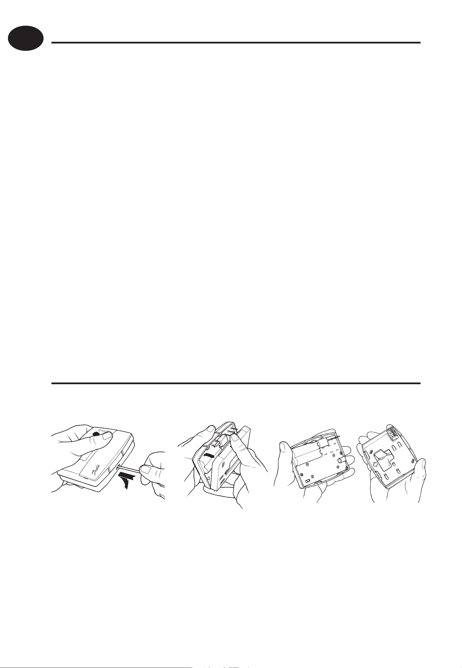
• First, remove the wallplate from the back of the unit.
• Ensure that there is a minimum of 50mm above the unit
and 100mm below the unit in order to mount the plug-in
module.
4
Page 5

5
• Fix at a height of
PS1
%
BYPASS
PS1
!
approximately 1.5m
from the fl oor, away
from draughts or heat
sources such a fan-coil
outlets, sunlight or
offi ce equipment.
Pipe sensor location
GB
• Fix the pipe sensor to the fl ow pipe using the clamping
band supplied.
Installation Instructions
!
Important note: It is essential that the circuit in which the
pipe sensor is located is not closed off and that water circulates
past the sensor at all times when the system is in operation.
This may require the fi tting of a bypass valve between system
fl ow and return to ensure circulation past the sensor.
Page 6

GB
X SEN
X SEN
N
L
FAN
1
COM
O/P
1 SPEED
FAN
ELECTRONICS
OUTPUT
COMMON IN
(LIVE IN)
PS1 PIPE
SENSOR
230 VAC
FIXED 3A
N
Wiring
2-pipe fan coil application
Installation Instructions
Note:
If HEAT/COOL/FAN outputs are 230V, link terminals L-COM
6
Page 7

7
Commissioning
ON
ON/OFF
CHRONO
°C
°F
Sw On
4
3
2
1
CHRONO 3CHRONO 6
Prior to re-fi tting the thermostat to the wallplate, the DIL switches on
the rear of the unit must be set to the desired setting.
GB
DIL Switch options, shown in factory set position.
Installation Instructions
Switch 4: If set to On/Off , both heating and cooling operates
Switch 3: Active only if switch 4 is set to Chrono. This switch
Switch 2: Allows Celsius or Fahrenheit temperature scaling to
in on/off mode. If set to Chrono, both heating and
cooling operates in chrono-proportional mode.
determines the number of cycles per hour that the
thermostat will impose on the system, the options
are three 20 minute cycles or six 10 minute cycles.
be selected.
Switch 1: Not used in this model.
Page 8

GB
Mounting thermostat to the wallplate
• To mount the thermostat to the wallplate, align the tabs on
the top of the thermostat with the apertures in the wallplate
and hinge the thermostat down, pressing fi rmly to engage
the securing clip in the wallplate.
Installation Instructions
Locking & limiting
• To lock or limit the setting range turn the setting dial to 3 and
remove knob.
• Position the locking springs on the rear of the dial to the
desired position and re-mount the knob ensuring that
number 3 on the dial aligns with the reference mark on the
case.
8
Page 9
9
LED fl ashes green during
compressor delay period
GB
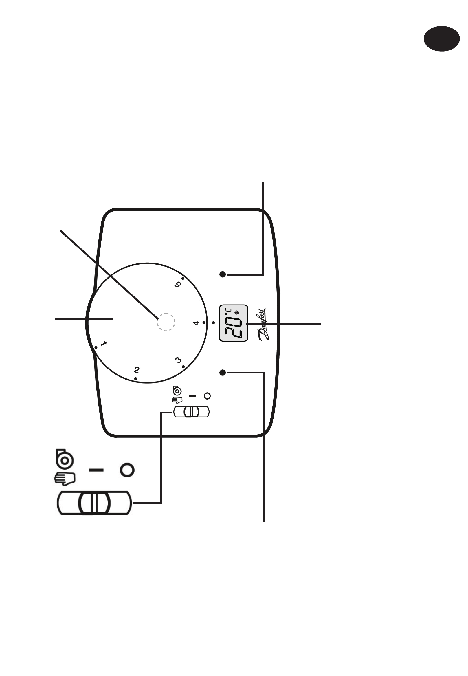
User Instructions
RESET
button
Temperature setting dial, read
setting off LCD display
LCD display, shows actual room temperature unless knob is moved at which time a
fl ashing set temperature is momentarily displayed. During heating demand a fl ame
symbol is lit, during cooling demand a snowfl ake symbol is lit
Fan runs continuously
Fan runs with heat or
cool demand
Thermostat off
LED lit green when
thermostat is powered
LED lit orange when fan
running
Note: Should it be necessary to reset the microprocessor for any reason, a reset button is located beneath the setting dial. Use a non-metallic
point, for example a match- stick to depress the recessed button.
Page 10

101112
Page 11

Page 12

www.danfoss.com/BusinessAreas/Heating
This product complies with the following EC Directives:
Electro-Magnetic Compatibility Directive.
(EMC) (2004/108/EC)
Low Voltage Directive.
(LVD) (2006/95/EC)
Part No 3500v01 08/08
 Loading...