

Datasheet
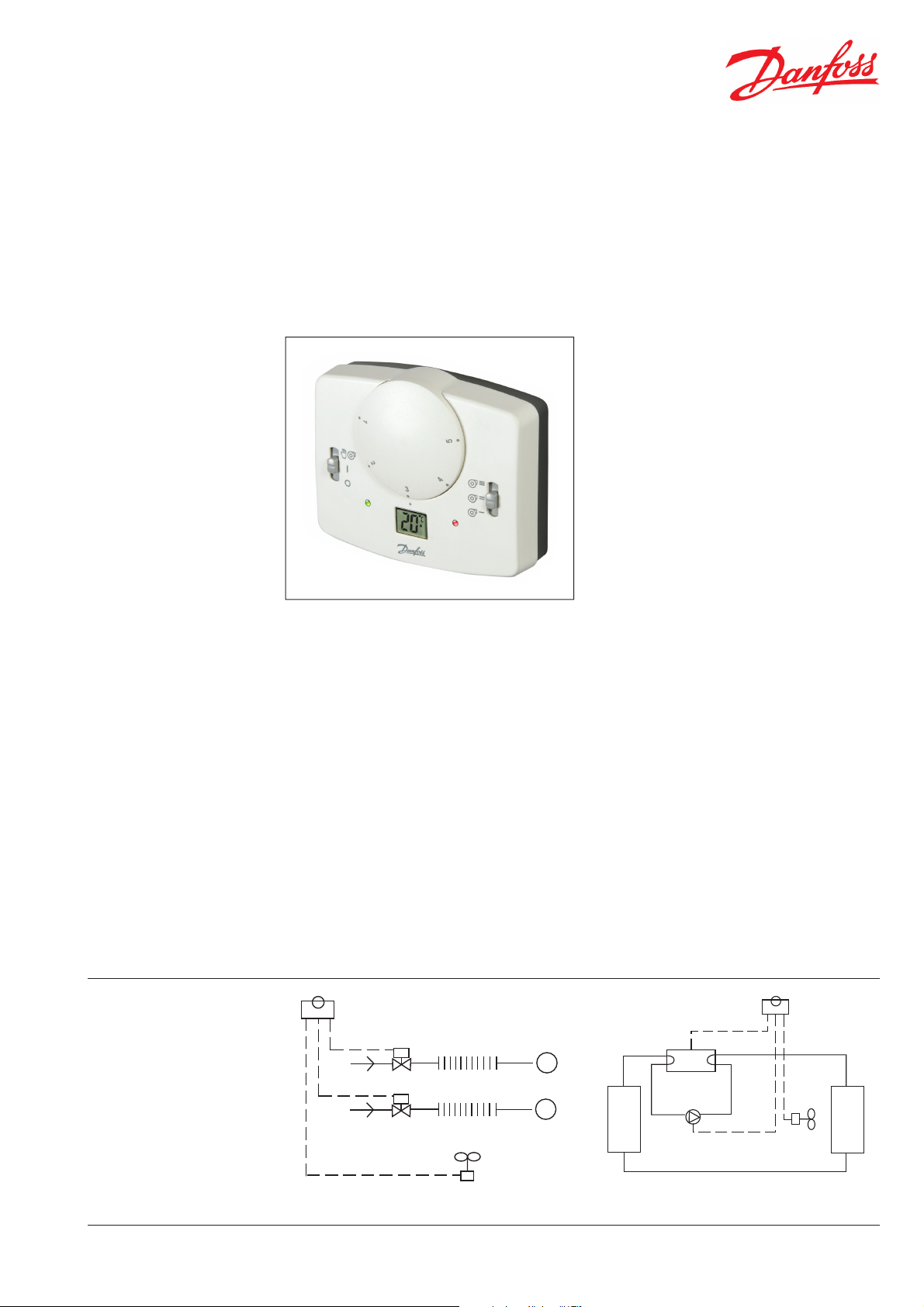
CRCT230HC1 and CRCT230HC3
Heat/Cool Room Thermostats
Features
The CRCT230HC range is designed for use in 4-pipe
fan-coil unit systems, split packaged systems and
in air to air heat-pump systems. The thermostat
design utilizes a microprocessor that in addition to
providing an intuitive analogue setting interface
with LCD display, also provides many enhanced
features adding to the fl exibility and versatility of
the product.
The thermostat incorporates a simple analogue
setting dial scaled 1 to 5, plus a small LCD display
which normally displays actual room temperature,
but changes momentarily to show set temperature
when the setting dial is moved. The set temperature
displayed on the LCD is the heating set point; an
installer selectable dead-band setting of either 2°C
or 4°C made during commissioning ensures that
there is no overlap between the separate heating
and cooling outputs.
In addition to the heating and cooling outputs,
the thermostat also incorporates a fan relay to
control the operation of a single phase fan motor.
A manual switch on the right hand face of the
3 speed versions of the thermostat allows the
user to manually select the required fan speed.
An additional manual switch on the left hand
face of the product allows the user to turn off
the thermostat and to select whether the fan is
switched on and off with the heating and cooling
outputs or runs continuously. LED indicators
provide clear indication of output status.
In addition to providing conventional on/off control,
the thermostat can be set up at time of installation to
provide chrono-proportional output of the heating
stage. If selected, the installer can determine the
cycle rate that the thermostat will impose on the
system using DIL switches on the rear of the unit.
This type of control mode provides closer control
accuracy compared to on/off control.
If used in air to air heat pump systems, the
thermostat can be set up at time of installation for
this type of system. This reconfi gures the heat &
cool outputs, allocating one to the control of the
compressor and one for the control of the reversing
valve which in turn dictates if the heat-pump
delivers hot or cold air. A built-in compressor delay
timer can be activated to prevent compressor
short cycling, the duration of the delay period can
also be set at time of installation. This compressor
delay timer function is also available for use in
non-heat-pump systems where cooling is derived
from a compressor.
For applications requiring remote air temperature
sensing, versions CRCT230HC1A and CRCT230
HC3A are also available.
• Simple analogue setting interface
• Suitable for 4-pipe fan coil unit systems
• Suitable for simple heat-pump systems
• Advanced microprocessor based design
Applications
Part No. 748v01 08/08
Fan-coil Control
+
-
-/+
R/V
-/+
Heat Pump Control
1
Datasheet CRCT230 HC-1/HC-3 Heat/Cool Room Thermostats
Specifi cation
Features 1-Speed Fan Model 3-Speed Fan Model
Built-in Sensor - Code no. CRCT230 HC1 - 082F1510 CRCT230 HC-3 - 082F1507
Remote Sensor - Code no. CRCT230 HC1A - 082F1511 CRCT230 HC3A - 082F1508
Manual 3-Speed Fan Switch •
Temperature range, heating 5 -30°C
Temperature range, cooling 7-32°C at dead-band of 2K
Temperature range, cooling 9-34°C at dead-band of 4K
Selectable dead-band 2 or 4K
Thermal diff erential /stage in on/off mode <1°C
Temperature accuracy ±1°C
Thermostat off /auto & fan on selector •
LCD display of set/room temperature •
Heat/cool output status LED •
Power on/ fan output status LED •
On/off or Chrono-proportional control •
Optional compressor delay timer •
Fan-coil or heat-pump confi guration •
Reversing valve heat or cool selection 1) •
Selectable Celsius or Fahrenheit scaling •
Maximum ambient temperature 45°C
Power supply 230Vac, ±10%, 50/60Hz
Relay outputs, heat, cool & fan 3 x SPST, 3(1)A, 10-230Vac
Dimensions, mm 110 wide, 90 high, 40 deep
Design standard EN60730-2-9
1) Reversing valve function only available if set up for heat-pump operation
Installer Settings
On/Off
°C
No Comp Del
3 Minutes
DB 2°C/4°F
Fan Coil Heat Pump
ON
RV-
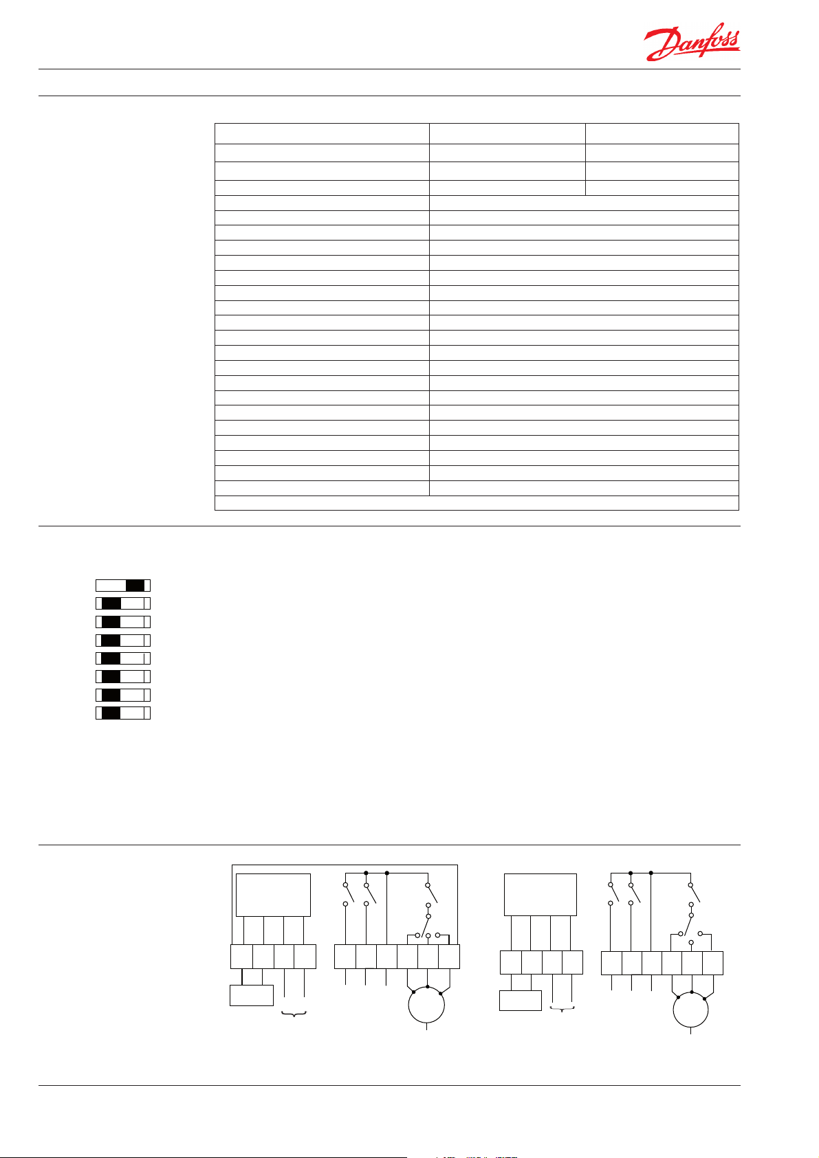
Wiring
Chrono
Chrono 3Chrono 6
°F
Comp Del
4 Minutes
DB 4°C/8°F
RV+
Switch 8: If set to On/Off , both heating and cooling
stages operate in on/off mode. If set to Chrono,
heating stage operates in chrono-proportional
modes, cooling continues in On/off mode.
Switch 7: Active only is switch 8 is set to Chrono.
This switch determines the number of cycles
per hour that the thermostat will impose on the
system, the options are three 20 minute cycles or
six 10 minute cycles.
Switch 6: Allows Celsius or Fahrenheit temperature
scaling to be selected.
Switch 5: Enables or disables a compressor delay
timer which is activated at the end of each cooling
call. This feature need only be used where cooling
is provided by a compressor as opposed to chilled
water. Set to Cmp del if a compressor delay is
required, otherwise leave set to No Cmp del.
Switch 4: Active only if switch 5 is set to Cmp del.
The options are 3 or 4 minutes.
ELECTRONICS
Switch 3: Allows dead-band between heating and
cooling to be set, options are 2°C or 4°C.
Switch 2: Allows application to set as fan coil or as
heat pump. If heat-pump is selected, the output
normally used to operate the heating valve is reassigned to the heat-pump reversing valve, the
compressor stop/start signal for both heat and
cool calls is re-assigned to the relay normally used
to operate the cooling valve.
Switch 1: The function of this switch is dependant
upon the setting of switch 2:
Switch 2 set to Fan-coil: Set to TS2, if the
thermostat has a remote sensor, the sensor is
treated as a room sensor.
Switch 2 set to Heat-pump: allows the reversing
valve to be set up to be energised in heating
mode (R+), or energised in cooling mode (R-).
ELECTRONICS
FAN 2FAN 1
3 SPEED
FAN
N
FAN 3
X SEN
X SEN
REMOTE
SENSOR
('A' MODELS ONLY)
N
230 VAC
FIXED 3A
COOL/
COM
COMP.
HEAT/
RV
COMPRESSOR
REVERSING VALVE
COMMON (LIVE IN)
L
FAN
1
FAN
2
3 SPEED
FAN
N
FAN
3
Notes
X SEN
X SEN
REMOTE
SENSOR
('A' MODELS ONLY)
N
N
230 VAC
FIXED 3A
HEAT/
COOL/C
L
L
OMP.
COM
RV
HEATING OUTPUT
COOLING OUTPUT
COMMON IN (LIVE IN)
(1) If HEAT/COOL/FAN outputs are 230V, link terminals L-COM.
(2) HC-1 and HC-1A models do not have a fan speed selector switch, fan is connected to terminal fan 1.
2
Part No. 748v01 08/08
Datasheet
CRCT230HCW1 and CRCT230HCW3
Heat/Cool Room Thermostats
Features
The CRCT230HCW1 and CRCT230HCW3 are
designed for use in 2-pipe fan-coil unit systems with
central changeover between heating and cooling.
The thermostat design utilizes a microprocessor
that in addition to providing an intuitive analogue
setting interface with LCD display, also provides
many enhanced features adding to the fl exibility
and versatility of the product.
The thermostat incorporates a simple analogue
setting dial scaled 1 to 5, plus a small LCD display
which normally displays actual room temperature,
but changes momentarily to show set temperature
when the setting dial is moved. A temperature
sensor mounted on the fl ow pipe work of the
system adjacent to the fan coil measures the
pipe temperature. If the measured temperature
exceeds 30°C the thermostat operates as a
heating thermostat, opening the fan coil control
valve on a fall of room temperature. Should the
measured fl ow temperature be less than 16°C,
the thermostat operates as a cooling thermostat,
opening the fan-coil unit control valve on a rise
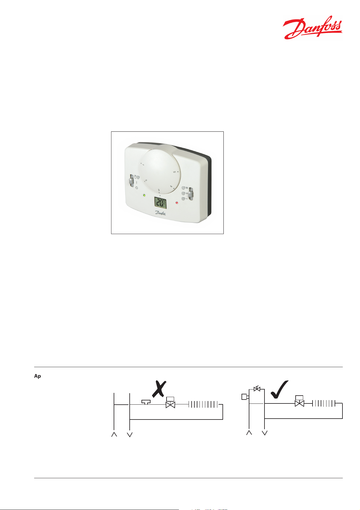
of room temperature. The pipe sensor must be
installed in a location where water fl ow across the
sensor can occur even if the fan-coil unit valve is
closed.
The thermostat also incorporates a fan relay to
control the operation of a single phase 3-speed
fan motor. A manual switch on the right hand face
of the 3-speed version of the thermostat allows
the user to manually select the required fan
speed. An additional manual switch on the left
hand face of the product allows the user to turn
off the thermostat and to select whether the fan
is switched on and off with the heating / cooling
output or runs continuously. LED indicators
provide clear indication of output status.
In addition to providing conventional on/off
control, the thermostat can be set up at time
of installation to provide chrono-proportional
output. If selected, the installer can determine the
cycle rate that the thermostat will impose on the
system using DIL switches on the rear of the unit.
This type of control mode provides closer control
accuracy compared to on/off control.
• Simple analogue setting interface
• Suitable for 2-pipe fan coil unit systems with
central changeover between heating and
cooling
• Thermostat function automatically changes
between heat and cool based upon pipe
temperature
• Advanced microprocessor based design
Applications
PS1
Part No. 748v01 08/08
%
BYPASS
PS1
!
3

Datasheet
Changeover temperature
CRCT230 HCW1 / HCW3 Heat/Cool Room Thermostats
Features 1-Speed Fan Model 3-Speed Fan Model
Built-in Room Sensor - code number CRCT230HCW1 - 082F1509 CRCT230HCW3 - 082F1506
Manual 3-speed fan selector •
Temperature range, heating 5 -30°C
Changeover temperature - Cool to Heat
hangeover temperature - Heat to cool
Thermal diff erential in on/off mode <1°C
Temperature accuracy ±1°C
Pipe sensor for heat/cool changeover •
Thermostat off /auto & fan on selector •
LCD display of set/room temperature •
Heat/cool output status LED •
Power on/ fan output status LED •
On/off or Chrono-proportional control •
Selectable Celsius or Fahrenheit scaling •
Maximum ambient temperature 45°C
Power supply 230Vac, ±10%, 50/60Hz
Relay outputs, heat/cool & fan 2 x SPST, 3(1)A, 10-230Vac
Dimensions, mm 110 wide, 90 high, 40 deep
Design standard EN60730-2-9
Pipe temperature >30°C
Pipe temperature <16°C
Installer Settings
On
ON/OFF
°C
ON
Wiring
CHRONO
CHRONO CHRONO 6
°F
Switch 4: If set to On/Off , both heating and cooling stages operate in on/off mode. If set to Chrono, heating stage operates in chrono-proportional
modes, cooling continues in On/off mode.
Switch 3: Active only is switch 4 is set to Chrono.
This switch determines the number of cycles per
hour that the thermostat will impose on the system, the options are three 20 minute cycles or six
10 minute cycles.
ELECTRONICS
FAN
FAN
X SEN
PS1 PIPE
SENSOR
X SEN
N
230 VAC
FIXED 3A
O/P
L
OUTPUT
COM
FAN
1
IN)
COMMON IN (LIVE
2
3 SPEED
FAN
N
3
Switch 2: Allows Celsius or Fahrenheit temperature scaling to be selected.
Switch 1: Not used in this model.
Notes
(1) If HEAT/COOL/FAN outputs are 230V, link terminals L-COM.
(2) HC-1 and HC-1A models do not have a fan speed selector
switch, fan is connected to terminal fan 1.
Danfoss can accept no responsibility for possible errors in catalogues, brochures, and other printed material. Danfoss reserves the right to alter its products without notice. This also applies to products already
on order provided that such alterations can be made without subsequent changes being necessary in specifications already agreed.
All trademarks in this material are property of the respective companies. Danfoss and the Danfoss logotype are trademarks of Danfoss A/S. All rights reserved.
Danfoss Randall Ltd.
Ampthill Road
Bedford MK42 9ER
Tel: 0845 1217 400
Fax: 0845 1217 515
Email: danfossrandall@danfoss.com
Website: www.danfoss-randall.co.uk
4
Part No. 748v01 08/08
VDEZB102
 Loading...