

Page 1
CRCP24CO1
Electronic Proportional Heat / Cool Thermostat
GB
Installation Instructions
User Instructions
Page 2

Index
INDEX
GB
Installation Instructions 3-6
User Instructions 8
2
Page 3
Installation Instructions
Please note
This product should only be installed by a suitably qualifi ed
electrician or heating installer. The installation must comply
with local Building Regulations and wiring Regulations,
including any competent person requirements that may exist.
Specifi cation
GB
Thermostat features
Temperature Range 10-30°C
Thermostat Heat, Standby, Cool
Selector
Power Supply 24 Vac ± 15%, 50/60Hz
Fan Output 3 (1) A, 10-230Vac, Type 1B
Control Method P+I, 2k Proportional Band
Dimensions (mm) 110 wide x 90 high x 40 high
Design Standard EN60730-2-9
Rated Impulse Voltage 2.5Kv
Ball Hardness Test 75°C
Control Pollution Situation Degree 2
Yes
Installation Instructions
Temperature Accuracy ±1°C
Control Output 0-10 Vdc
Common Supply 10 - 230 Vac
3
Page 4
GB
Installation Instructions
Product overview
This thermostat is designed for fan coil and chilled beam
applications alongside proportional valves and actuator systems
where a 0-10v proportional control output is required.
The thermostat also has a single speed fan output.
The operational mode of the fan (auto or continuous) is selected
at time of installation via DIL switches accessible on the rear of
the unit.
When the unit is in standby the fans are switched off .
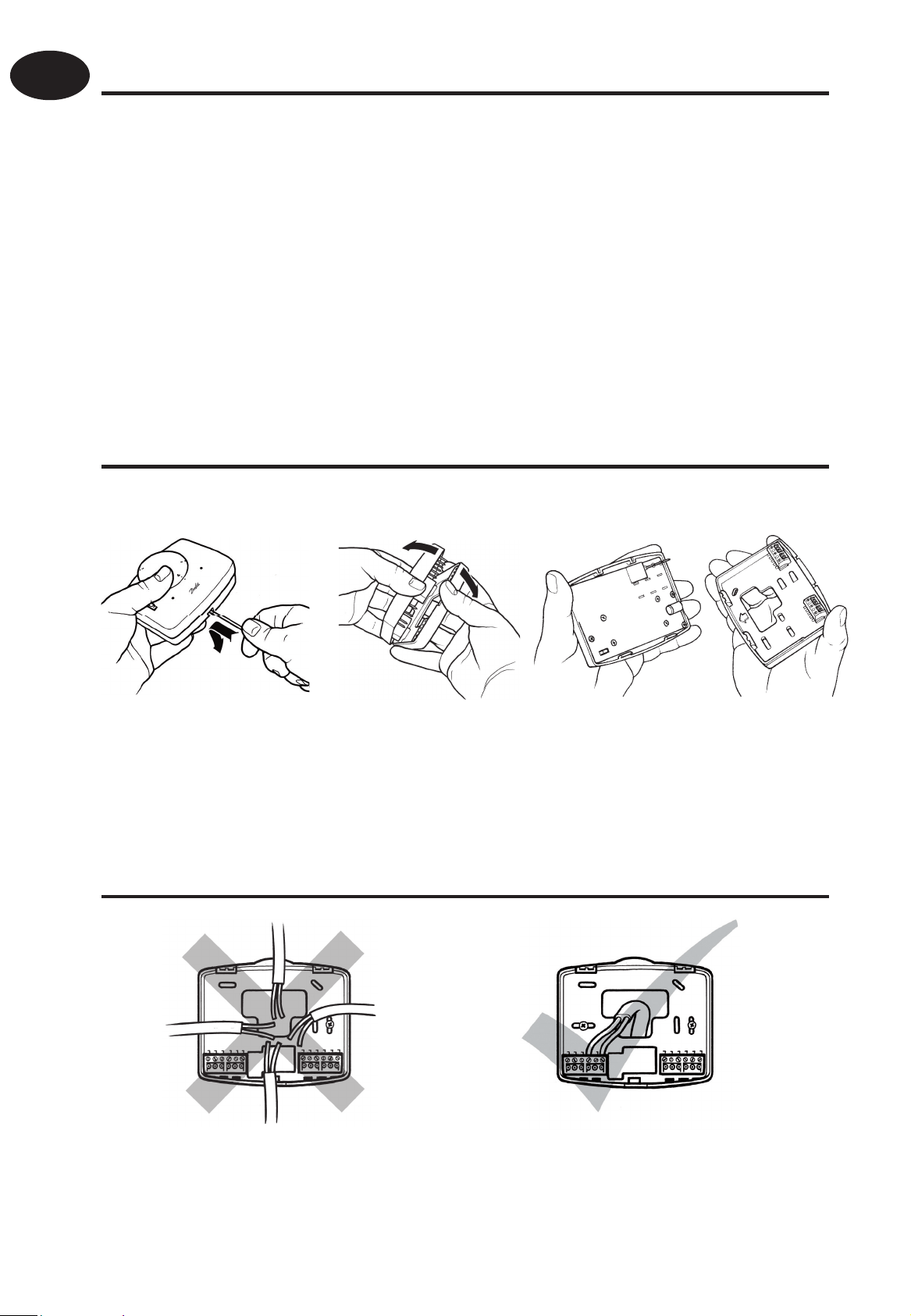
Installation
First remove the wallplate from the back of the unit.
Fix at a height of approximately 1.5m from the fl oor, away
from draughts or heat sources such as fan-coil outlets,
sunlight or offi ce equipment.
Wiring
4
Page 5

Connection Diagram
Electronics
GB
Cool
Heat
0-10V outputs
AB
0V
24 Vac
Heating
Cooling
24V
or
0V/
return
COM
Common In
Fan 1
1 Speed
Fan
N
Commissioning
Prior to re-fi tting the thermostat to the wallplate, the DIL switches
on the rear of the unit must be set to the desired setting.
Installation Instructions
5
Page 6

GB
DIL Switch options, shown in factory set position.
Sw On
1
2
Fan Con
MOT
Fan Auto
WAX
DIL Switch Descriptions
Switch 1: Fan Con - Fan will run whenever thermostat is in
Installation Instructions
Fan Auto - Fan will run whenever temperature is
heating or cooling mode.
0.2°C or more above/below (depending on heat/cool
mode) setpoint. When temperature reaches setpoint,
the fan will switch off .
Switch 2: MOT - Motorised valve actuator selection.
WAX - Wax valve actuator selection.
Mounting thermostat to the wallplate
To mount the thermostat to the wallplate, align the tabs on
the top of the thermostat with the apertures in the wallplate
and hinge the thermostat down, pressing fi rmly to engage
the securing clip in the wallplate.
6
Page 7

Locking & limiting
To lock or limit the setting range turn the setting dial to 3 and
remove knob.
Position the locking springs on the rear of the dial to the
desired position and re-mount the knob ensuring that
number 3 on the dial aligns with the reference mark on the
case.
GB
Installation Instructions
7
Page 8

GB
User Instructions
User Instructions
Setting the temperature
Turn the setting dial to the required temperature.
Frost Protection
To activate frost protection, turn the dial below 10°C. Frost
protection becomes active at 8°C. If the temperature in the room
drops below 8°C then the output will activate.
When frost protection is activated the right LED will turn orange.
Standby Mode
In cooling mode, the standard frost protection is not available;
instead there is standby mode. When the dial is turned past 10°C
the unit enters standby mode and cooling will be inactive until the
dial is turned up past 10°C.
8
Page 9
LED off when setpoint reached
LED red when heating
LED green when cooling
LED orange when frost
protection activated
GB
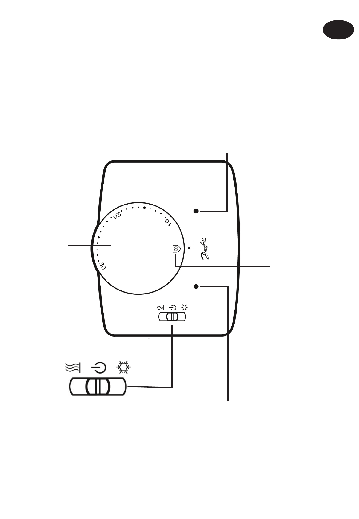
User Instructions
Temperature setting dial
Heat Mode
Standby Mode
Frost protection mode
Cool Mode
LED lit green when
thermostat is powered
and fan is in continuous
mode
LED lit orange when fan
is running in auto mode
9
Page 10

101112
Page 11

Page 12

www.danfoss.com/BusinessAreas/Heating
(2004/108/EC)
(2006/95/EC)
Part No 25292v01 07/08
 Loading...