

Page 1
Data Sheet
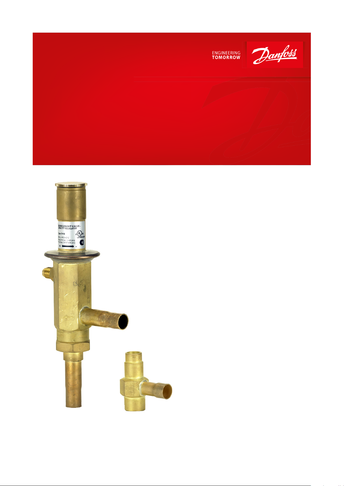
Hot gas bypass regulator and
Liquid gas mixer
Type CPCE and LG
CPCE hot gas bypass regulator adapt compressor capacity to actual evaporator load.
CPCE hot gas bypass regulator adapt
compressor capacity to actual evaporator load.
They are designed for installation in a bypass
line between the low and high pressure sides of
the refrigeration system, for hot gas injection
between the evaporator and thermostatic
expansion valve.
Injection should be arranged to occur through
an LG liquid gas mixer.
Features
CPCE hot gas bypass regulator
• Superior control accuracy
• Direct connection to system suction line
regulates hot gas injection independent
of evaporator pressure drop
• The regulator increases evaporator gas
velocity, thus ensuring better oil return to
compressor
• Protection against too low an evaporating
temperature, i.e. prevents evaporator icing
• May be used in the following EX range:
Category 3 (Zone 2)
LG liquid gas mixer
• LG provides homogeneous mixing of the
liquid and hot gas refrigerant injected into
the evaporator
• Prevents high suction superheat by
combining hot gas injection with expansion
valve characteristics
• LG can be used for hot gas defrosting or
reverse cycle systems
AI246086497130en-001501
Page 2
Danfoss
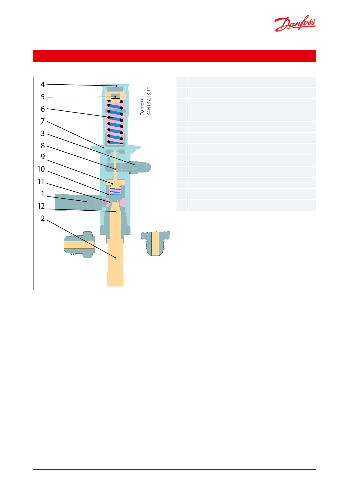
34N132.13.10
4
3
10
6
1
5
8
11
7
9
12
2
123456789101112Inlet
Outlet
Pilot pressure connection
Protective cap
Setting screw
Main spring
Diaphragm
Pressure pin
Pilot orice
Servo piston
Pressure equalising hole
Main orice
Hot gas bypass regulator and Liquid gas mixer, type CPCE and LG
Functions
Figure 1: CPCE
Hot gas bypass regulator, type CPCE is servo-operated.
The diaphragm (7) is actuated on the upper side by the force developed by the spring (6) and on the lower side by
the pilot pressure from (3). When the pilot pressure drops below the preset value, the throttling ball is forced away
from the pilot orice (9) by the spring which acts via the pressure pin (8).
The pressure over the servo piston (10) is then relieved. The dierential pressure which is thus created moves the
servo piston up and causes the regulator to open so that hot gas is able to ow to the suction side.
When the pilot pressure rises above the setting, the pilot orice shuts o the evacuation from the space over the
servo piston. Pressure then builds up again over the piston via the pressure equalising hole (11), thus closing the
regulator.
© Danfoss | Climate Solutions | 2021.02 AI246086497130en-001501 | 2
Page 3
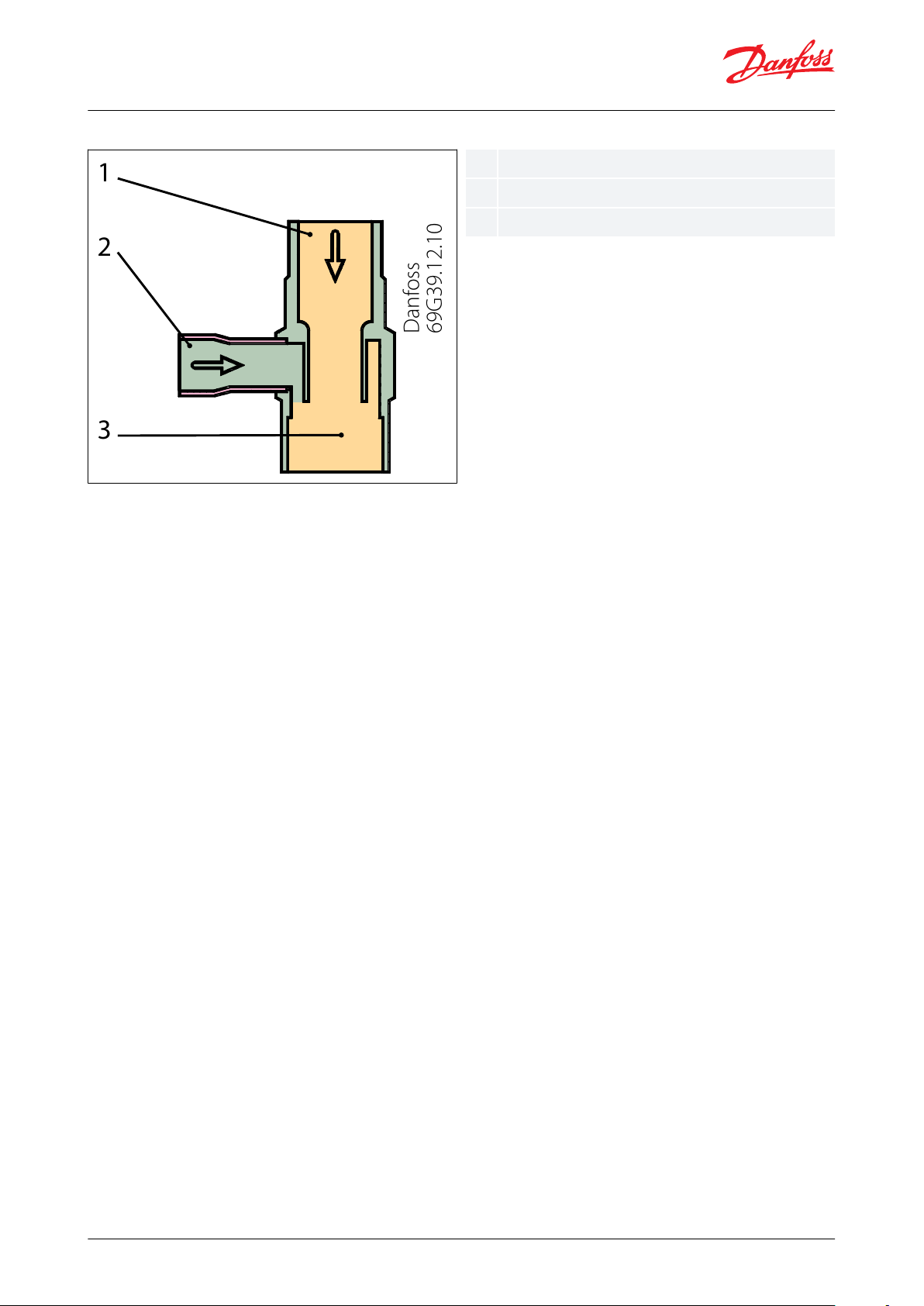
Danfoss
69G39.12.10
1
2
3
123
Liquid inlet
Hot gas inlet
Outlet
Hot gas bypass regulator and Liquid gas mixer, type CPCE and LG
Figure 2: LG
© Danfoss | Climate Solutions | 2021.02 AI246086497130en-001501 | 3
Page 4
Range
Description
Refrigerants
R22, R1234ze *), R1270 *), R134a, R290 *), R404A, R407A, R407C, R407F, R448A,
R449A, R450A, R452A, R507A, R513A, R600 *),
R600a *)
*) only LG 12-16 and LG 16-22 ; see more details in the note below the table
Regulating range
pe = 0 – 6 bar
Factory setting = 0.4 bar
Maximum working pressure
PS/MWP = 28 bar
Maximum test pressure
Pe = 31 bar
Maximum dierential pressure
Δp = 18 bar
Maximum media temperature
140 °C
Minimum media temperature
-50 °C
Hot gas bypass regulator and Liquid gas mixer, type CPCE and LG
Product specications
Technical data
Table 1: Pressure range
This product is evaluated for R290, R600, R600a, R1234ze, R1270 by ignition source assessment in accordance with
standard EN ISO80079-36. Flare connections are only approved for A1 and A2L refrigerants.
For complete list of approved refrigerants, visit www.products.danfoss.com and search for individual code numbers,
where refrigerants are listed as part of technical data.
Sizing
For optimum performance, it is important to select a CPCE valve according to system conditions and application.
The following data must be used when sizing a CPCE valve:
• Refrigerant: HCFC, HFC and HC
• Minimum suction temperature: ts in [°C] / [bar]
• Compressor capacity at minimum suction temperature: Q1 in [kW]
• Evaporator load at minimum suction temperature: Q2 in [kW]
• Liquid temperature ahead of expansion valve: tl [°C]
• Reduction of suction temperature/suction pressure in [K]
• Connection type: are or solder
• Connection size in [in] or [mm]
Selection
Example
When selecting the appropriate valve it may be necessary to convert the actual capacity using a correction factor.
This is required when system conditions are dierent from table conditions.
The following examples illustrate how this is done.
• Refrigerant: R404A
• Minimum suction temperature: ts = -30 °C
• Compressor capacity at -30 °C, Q1= 80 kW
• Evaporator load at -30 °C, Q2 = 60 kW
• Liquid temperature ahead of expansion valve: tl = 40 °C
• Reduction of suction temperature/suction pressure = 5 K
• Connection type: solder
• Connection size =
1
⁄2 in
Step 1
Determine the replacement capacity. This is done by taking the compressor capacity at minimum suction
temperature Q1 minus evaporator load at minimum suction temperature Q2. Q1- Q2=80-60=20 kW
© Danfoss | Climate Solutions | 2021.02 AI246086497130en-001501 | 4
Page 5

Suction temp. t
s
after reduction
[°C]
Refrigerant
Suction temperature Δt
s
[K]
10
R134a
0.1
0.5
0.9
1.0
1.0
1.0
1.0
R22, R404A,
R507, R407C
0.3
0.9
1.0
1.0
1.0
1.0
1.0
0
R134a
0.1
0.3
0.7
1.0
1.0
1.0
1.0
R22, R404A,
R507, R407C
0.2
0.9
1.0
1.0
1.0
1.0
-10
R134a
0.1
0.3
0.6
1.0
1.3
1.4
1.4
R22, R404A,
R507, R407C
0.1
0.5
1.0
1.0
1.0
1.0
1.0
-20
R134a
0.1
0.3
0.6
1.0
1.5
2.2
2.4
R22, R404A,
R507, R407C
0.1
0.3
0.7
1.0
1.0
1.0
1.0
-30
R134a
0.1
0.3
0.6
1.0
1.5
2.2
2.9
R22, R404A,
R507, R407C
0.1
0.3
0.6
1.0
1.3
1.4
1.4
-40
R22, R404A,
R507, R407C
0.1
0.3
0.6
1.0
1.5
2.0
2.2
Type
Suction temperature
ts after pressure /
temperature reduc‐
tion [°C]
Regulator capacity Q [kW] at condensing temperature tc [°C]
2030405060
R22
CPCE 12
10
7.9
16.3
21.6
26.9
33.4012.9
17.3
21.7
27.1
33.4
-10
13.6
17.42227.4
33.4
-20
13.7
17.6
22.2
27.7
33.4
-30811
14.7
18.6
33.4
-40
4.3
5.7
7.6–33.4
CPCE 15
10
11.52431.7
39.4490
18.8
25.43239.949-102025.6
32.3
40.249-20
20.1
25.8
32.6
40.749-30
11.51621.2
27.149-40
5.9
7.8
10.6–49
Hot gas bypass regulator and Liquid gas mixer, type CPCE and LG
Step 2
Determine the correction factor for the reduction of suction temperature / suction pressure. From the correction
factor table a suction temperature reduction of 5 K (R404A) corresponds to a factor of 1.3.
Table 2: Refrigerant and Suction temperature
The correction table is used when suction temperature change deviates from 4 K. The replacement capacity must be
divided by the correction factor determined.
Step 3
Corrected replacement capacity is Q=20/1.3=15.4 kW
Step 4
Now select the appropriate capacity table for R404A and choose the column with a suction temperature of ts = -30
°C. Using the corrected replacement capacity, select a valve that provides an equivalent or greater capacity. A CPCE
12 delivers a replacement capacity of 17.9 kW at a minimum suction temperature of -30 °C.
Step 5
CPCE 12,
1
⁄2 in solder connection, code no. 034N0082.
Capacity tables
© Danfoss | Climate Solutions | 2021.02 AI246086497130en-001501 | 5
Page 6

Type
Suction temperature
ts after pressure /
temperature reduc‐
tion [°C]
Regulator capacity Q [kW] at condensing temperature tc [°C]
2030405060
CPCE 22
10
15.2
31.74252.3
64.9025
33.6
42.4
52.8
64.9
-10
26.53442.8
53.4
64.9
-20
26.6
34.2
43.1
53.8
64.9
-30
15.4
21.3
28.1
35.9
64.9
-40810.7
14.3–64.9
R134a
CPCE 12
10
2.3
10.4
14.41822.607.8
11.3
14.4
18.1
22.6
-10
5.8
7.9
10.8
14.4
18.1
-20
3.4
4.6
6.1
8.3
10.6
-3022.8
3.7
4.9
6.2
CPCE 15
10
2.3
15.2
21.1
26.5
33.2011.4
16.6
21.2
26.6
33.2
-10
8.3
11.6
15.7
21.1
26.6
-20
4.8
6.6
8.8
11.9
15.2
-30
2.6
3.5
4.9
6.4
8
CPCE 22
10
3.1
20.42835.2
43.9015.1
22.8
28.1
35.2
43.9
-10
10.9
15.2
20.9
27.7
35.2
-20
6.4
8.8
11.8
15.7
20.3
-30
3.756.8
8.9
11.3
R404A/R507
CPCE 12
10
7.5
15.5
20.6
25.7
31.1012.2
16.4
20.6
25.7
31.1
-10
12.9
16.4
20.7
25.7
31.1
-20
13.1
16.4
20.7–31.1
-30
10.3
13.8
17.9–31.1
-40
5.5
7.5
9.5–31.1
CPCE 15
101122.8
30.3
37.8
46.9018
24.2
30.3
37.8
46.9
-10
19.1
24.2
30.4
37.8
46.9
-20
19.1
24.3
30.4–46.9
-301520.3
26.5–46.9
-40810.6
13.4–46.9
CPCE 22
10
14.6
30.2
40.1
49.9
62.3023.83240.1
49.9
62.3
-10
25.33240.15062.3
-20
25.3
32.1
40.2–62.3
-30
19.9
26.7
34.8–62.3
-40
10.6
14.218–
62.3
R407C
CPCE 12
10
9.7
18.3
23.5
28.2
33.4014.41923.2
27.9
33.4
-10
15.11923.3
27.4
33.4
-20
15.1
18.8
23.1
27.4
33.4
-30
8.7
11.71518
33.4
-40
4.6
5.9
7.6–33.4
CPCE 15
10
14.1
26.9
34.6
41.4490
21.1
27.9
34.2
41.149-10
22.2
27.9
34.2
40.249-20
22.1
27.6
33.9
40.349-30
12.51721.6
26.349-40
6.3
8.1
10.6–49
Hot gas bypass regulator and Liquid gas mixer, type CPCE and LG
© Danfoss | Climate Solutions | 2021.02 AI246086497130en-001501 | 6
Page 7

Type
Suction temperature
ts after pressure /
temperature reduc‐
tion [°C]
Regulator capacity Q [kW] at condensing temperature tc [°C]
2030405060
CPCE 22
10
18.7
35.5
45.8
54.9
64.90283745.4
54.4
64.9
-10
29.4
37.1
45.4
53.4
64.9
-20
29.3
36.6
44.8
53.3
64.9
-30
16.8
22.6
28.7
34.8
64.9
-40
8.6
11.1
14.3–64.9
Danfoss
34N133.13
Type
L
1
Net weight
CPCE 12
10
0.9
CPCE 15
12
0.9
CPCE 22
17
0.9
Danfoss
69G40.12
Hot gas bypass regulator and Liquid gas mixer, type CPCE and LG
The capacities are determined by reducing the suction temperature/suction pressure at Δts = 4 K. The given suction
temperatures are minimum values, i.e. after reduction.
The capacities are made up of the CPCE hot gas capacity + the extra capacity given by the thermostatic expansion
valve to maintain the superheat after of the evaporator constant
Dimensions and weights
Figure 3: CPCE
Table 3: Dimensions and weight for CPCE
Figure 4: LG
© Danfoss | Climate Solutions | 2021.02 AI246086497130en-001501 | 7
Page 8

Type
H
H1L
1
NV
Net weight
LG 12 – 1654224024
0.1
LG 12 – 2262264228
0.2
LG 16 – 2879354836
0.3
LG 22 – 3589406641
0.4
Hot gas bypass regulator and Liquid gas mixer, type CPCE and LG
Table 4: Dimensions and weight for LG
© Danfoss | Climate Solutions | 2021.02 AI246086497130en-001501 | 8
Page 9

Type
Connection
Rated capacity
(1)
[kW]
Code no.
Flare
Solder
R22
R134a
R404A/R507
R407C
[in]
[mm]
[in]
[mm]
CPCE 12
1/212––17.4
7.9
16.4
19.0
034N0081
CPCE 12––
1/21217.4
7.9
16.4
19.0
034N0082
CPCE 15––
5/81625.6
11.6
24.2
27.9
034N0083
CPCE 22––
7/82234.0
15.2
32.0
37.1
034N0084
Type
Connection
Code no.
Outlet ODM
Inlet hot gas ODF
Inlet liquid ODF
[in]
[mm]
[in]
[mm]
[in]
[mm]
LG 12 – 16
5/8161/212 5/8
16
069G4001
LG 12 – 22
7/8221/212 7/8
22
069G4002
LG 16 – 28
1 1/8285/8161 1/8
28
069G4003
LG 22 – 35
1 3/8357/8221 3/8
35
069G4004
Hot gas bypass regulator and Liquid gas mixer, type CPCE and LG
Ordering
Hot gas bypass regulator
Figure 5:
Regulator
(1)
(1)
The rated capacity is the regulator capacity at:
The rated capacity is the regulator capacity at:
- evaporating temperature te = -10 °C,
- evaporating temperature te = -10 °C,
- condensing temperature tc = 30 °C,
- condensing temperature tc = 30 °C,
- reduction of suction temperature / suction pressure ∆ts = 4 K.
- reduction of suction temperature / suction pressure ∆ts = 4 K.
Figure 6: Liquid
gas mixer
© Danfoss | Climate Solutions | 2021.02 AI246086497130en-001501 | 9
Page 10

Document name
Document type
Document topic
Approval authority
RU Д-DK.БЛ08.В.00191_18
EAC Declaration
Machinery & Equipment
EAC
MD 034N0625.AA
Manufacturers Declaration
PED
Danfoss
Hot gas bypass regulator and Liquid gas mixer, type CPCE and LG
Certcates, declaration and approvals
The list contains all certicates, declarations, and approvals for this product type. Individual code number may have
some or all of these approvals, and certain local approvals may not appear on the list.
Some approvals may change over time. You can check the most current status at danfoss.com or contact your local
Danfoss representative if you have any questions.
Table 5: Certicates, declaration and approvals
© Danfoss | Climate Solutions | 2021.02 AI246086497130en-001501 | 10
Page 11

Online support
Danfoss oers a wide range of support along with our products, including digital product information, software,
mobile apps, and expert guidance. See the possibilities below.
The Danfoss Product Store
The Danfoss Product Store is your one-stop shop for everything product related—no matter where
you are in the world or what area of the cooling industry you work in. Get quick access to essential
information like product specs, code numbers, technical documentation, certications, accessories,
and more.
Start browsing at store.danfoss.com.
Find technical documentation
Find the technical documentation you need to get your project up and running. Get direct access to
our ocial collection of data sheets, certicates and declarations, manuals and guides, 3D models
and drawings, case stories, brochures, and much more.
Start searching now at www.danfoss.com/en/service-and-support/documentation.
Danfoss Learning
Danfoss Learning is a free online learning platform. It features courses and materials specically
designed to help engineers, installers, service technicians, and wholesalers better understand the
products, applications, industry topics, and trends that will help you do your job better.
Create your Danfoss Learning account for free at www.danfoss.com/en/service-and-support/learning.
Get local information and support
Local Danfoss websites are the main sources for help and information about our company and
products. Find product availability, get the latest regional news, or connect with a nearby expert—all
in your own language.
Find your local Danfoss website here: www.danfoss.com/en/choose-region.
Coolselector®2 - nd the best components for you HVAC/R system
Coolselector®2 makes it easy for engineers, consultants, and designers to nd and order the best
components for refrigeration and air conditioning systems. Run calculations based on your operating
conditions and then choose the best setup for your system design.
Download Coolselector®2 for free at coolselector.danfoss.com.
Danfoss can accept no responsibility for possible errors in catalogues, brochures and other printed material. Danfoss reserves the right to alter its
products without notice. This also applies to products already on order provided that such alterations can be made without subsequential
changes being necessary in specications already agreed. All trademarks in this material are property of the respective companies. Danfoss and
the Danfoss logotype are trademarks of Danfoss A/S. All rights reserved.
© Danfoss | Climate Solutions | 2021.02 AI246086497130en-001501 | 11
 Loading...