

Page 1
Service Kit Instructions
Series 90 variable pumps
Charge pressure relief valve adjustment
CHARGE PRESSURE
RELIEF VALVE
ADJUSTMENT
Warning
The following procedure
may require the ve hicle/
machine to be disabled
(wheels raised off the
ground, work function
disconnected, etc.) in order
to prevent injury to the
technician and by standers.
Take necessary safety
precau tions before moving
the vehicle/machine.
The following procedure explains how to check and adjust the charge pressure relief
valve.
1. Install a 50 bar [1000 psi] pressure gauge in the pump charge pres sure gauge port
(M3). Install a 10 bar [100 psi] gauge to measure case pres sure (tee into L1 or L2 or
use servo gauge port M4 or M5). Operate the system with the pump in neutral (zero
displacement) when measuring pump charge pressure.
2. The table shows the acceptable pump charge pressure range for some charge relief
valve settings. These pressures assume 1500 min¯¹ (rpm) and a reservoir temperature
of 50°C [120°F], and are referenced to case pressure.
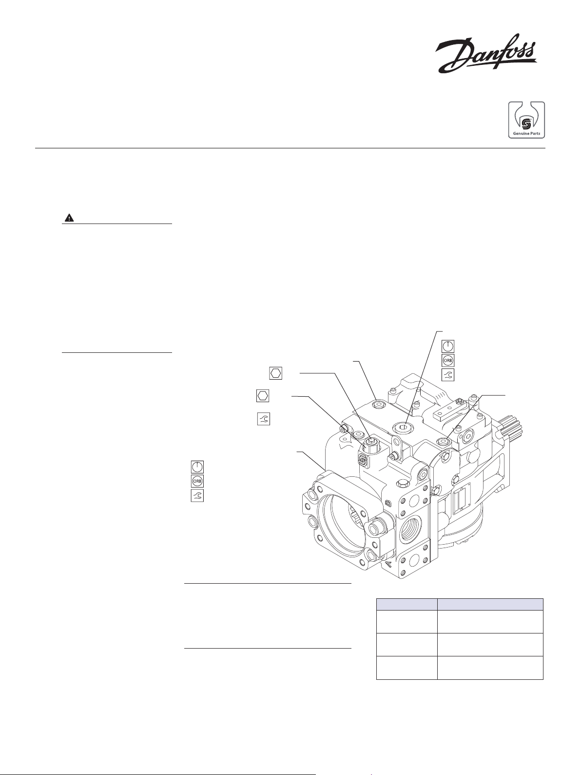
Charge pressure relief valve
Case drain port L1
0 - 10 bar [0 - 100 psi]
M4
K90
Adjusting screw
K10
Lock nut
52 N•m [39 lbf•ft]
Charge pressure gauge port M3
0 - 50 bar [0 - 1000 psi]
9/16-18
23 N•m [17 lbf•ft]
1 1/16-12
115 N•m [85 lbf•ft]
M5
© Danfoss, 2013
See appropriate table
Listed pressures assume a pump speed
of 1500 min-1 (rpm). At higher pump
input speeds (with higher charge flows)
the charge pressure will rise over the
rated set ting.
11085721 • Rev AB • September 2013 1
P106 162E
Charge pressure ranges
Model code Measured charge pressure*
20
24
28
* This is the actual charge pressure port gauge
reading minus the case pressure port gauge
reading.
18.1 – 21.7 bar
[262 –315 psi]
22.0 – 26.9 bar
[319 – 390 psi]
25.8 – 30.7 bar
[37.4 – 44.5 psi]
Page 2

CHARGE PRESSURE
RELIEF VALVE
ADJUSTMENT
(continued)
3. Later production Series 90 pumps have an external screw-adjustable charge
pressure relief valve. Loosen locknut (K10) and turn the adjusting screw (K90) using a
screwdriver or 1/2 in. hex wrench to adjust charge pres sure setting.
Lock nut wrench size
Frame size Wrench size
030 – 100 1-1/16 inch
130 – 250 1-5/8 inch
4. Clockwise rotation of the plug increases the setting and counterclockwise rotation
decreases the setting (at a rate of approximately 3.9 bar [50 psi] per turn). Torque
lock nut to 52 N•m [39 lbf•ft].
5. Once you achieve the desired charge pressure setting, remove the gauges and plug
the ports.
© Danfoss, 2013
11085721 • Rev AB • September 2013 2
 Loading...