

Page 1
Data Sheet
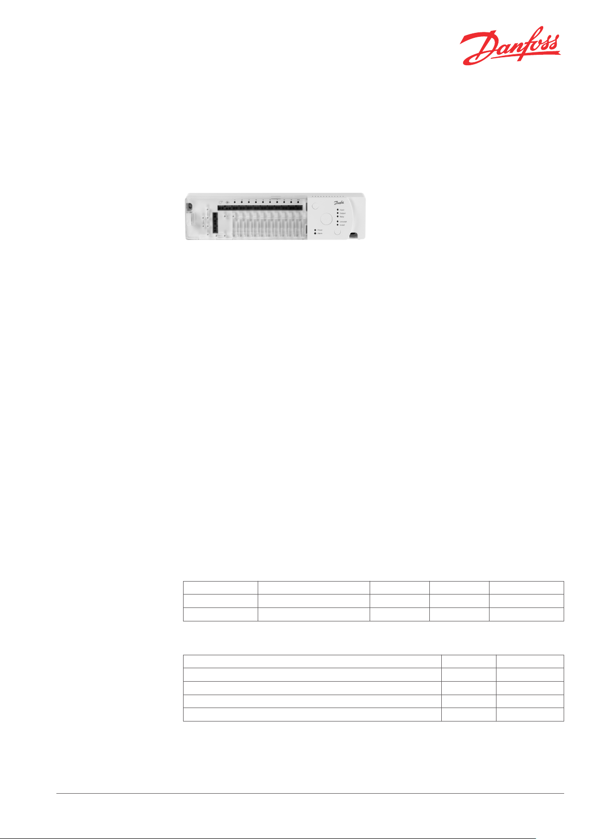
CF-MC Master Controller
Application
CF-MC is the Master Controller in Danfoss' CF2
wireless floor heating control system.
2-way wireless communication between CF-MC
and other wireless CF2+ system components
ensures a high level of transmission security and
makes it possible to perform Link test of the
signals.
Transmission range is up to 30 m in normal
buildings. If transmission is reduced or blocked
by building or interior elements, a CF-EA external
antenna (accessory) can be used to avoid the
obstacles.
CF-MC is connected directly to 230 V power
supply, and it provides all actuator outputs with
with 24 V.
CF-MC Master Controller includes features like:
2-way wireless transmission at 868.42MHz,
▪
for higher transmission security
Direct link test option on each system
▪
component
Wireless assignment of room thermostats
▪
and other system components
5 or 10 short-circuit protected outputs with
▪
LED indication
Outputs for 24V NC or NO actuators
▪
Valve motion for all outputs for approx. 12
▪
min. every 14th day with no heat demand
PWM (Pulse Width Modulation) principle
▪
Input (On/Off) for heating / cooling
▪
Input for PT1000 pipe sensor
▪
Input (On/Off) for global standby (can also
▪
be used for CF-DS dew-point sensor)
Relay for pump control with automatic
▪
pump motion
Relay for boiler control, activated only at
+
▪
heat demand
Easy cable fixing at each actuator output for
▪
several cable types
Automatic self diagnosis of errors
▪
Larger CF2+ systems can consist of 2 or 3 CF-MC
Master Controllers with up to 30 outputs.
Systems with more Master Controllers can be
accessed by a single wireless CF-RC Remote
Controller, which gives access to even more
functionality and features, e.g.
Individual settings for each Master
▪
Controller output
Override and locking of local room
▪
temperature settings
Setback and period programming
▪
System status etc.
▪
Forecast
▪
Low enrgy optimizer
▪
Control of cooling applications
▪
Find more information in data sheet and
instruction for CF-RC.
Ordering
Accessories
Danfoss Heating Solutions VDSPK102 © Danfoss 07/2011 1
Product Outputs Supply Type Code no.
Master Controller 5 outputs, 24 VDC 230 VAC CF-MC 088U0245
Master Controller 10 outputs, 24 VDC 230 VAC CF-MC 088U0240
Product Type Code no.
External antenna with 2 m cable CF-EA 088U0250
Cable extension for external antenna, 5 m CF-EC 088U0255
TWA-A 24 V NC actuator for Danfoss valves TWA-A 088H3110
TWA-A 24 V NO actuator for Danfoss valves TWA-A 088H3111
Page 2
L N
9 10876 54321
L N
¡
¡
¡
¡
¡
¡
230 V~
50 Hz
max.
3 m
325
79
51
Data Sheet CF-MC Master Controller
Technical data
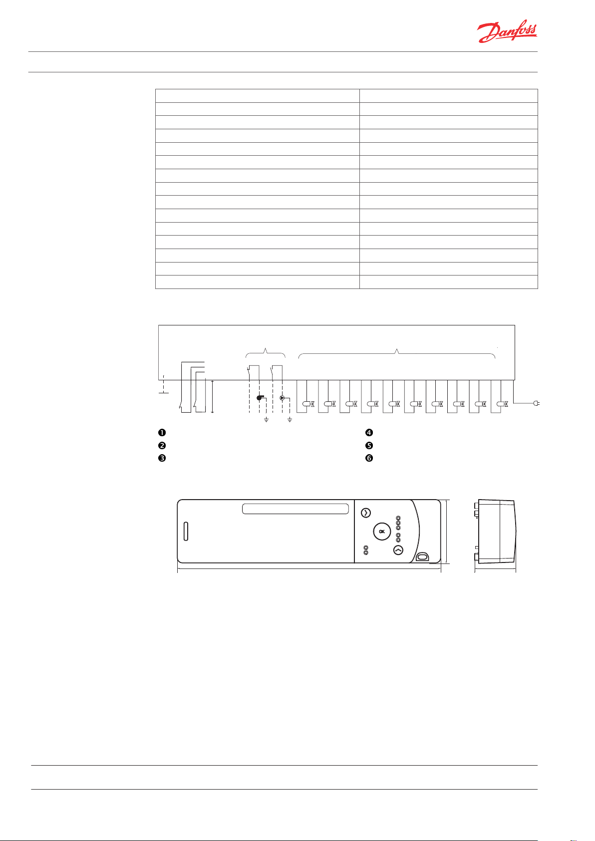
Wiring Connections
Supply voltage 230 VAC
Output voltage 24 VDC
Number of outputs 5 / 10
Transmission frequency 868.42 MHz
Transmission range up to 30 m (in normal buildings)
Transmission power < 1 mW
Max. running load of actuator output 35 VA (total for all outputs)
Max. load for pump relay 230 V, 8 A / 2 A (inductive)
Max. load for boiler relay 230 V, 8 A / 2 A (inductive)
Approvals CE
Standard EN 60730
Directives R&TTE, LVD, EMC
Protection class IP30
Length of mains cable 1.5 m
Weight 700 g
PT 1000 pipe sensor. Relay outputs.
Global standby. Actuator outputs.
Heating / Cooling. External antenna.
Dimensions
Danfoss A/S
Heating Solutions
Haarupvaenget 11
8600 Silkeborg
Denmark
Phone:+45 7488 8000
Fax: +45 7488 8100
Email: heating.solutions@danfoss.com
www.heating.danfoss.com
Danfoss can accept no responsibility for possible errors in catalogues, brochures and other printed material. Danfoss reserves the right to alter its products without notice. This also applies to products
already on order provided that such alterations can be made without subsequential changes being necessary in specifications already agreed. All trademarks in this material are property of the respective
companies. Danfoss and the Danfoss logotype are trademarks of Danfoss A/S. All rights reserved.
2 VDSPK102 © Danfoss 07/2011 Danfoss Heating Solutions
Page 3
CF-RF
Data Sheet
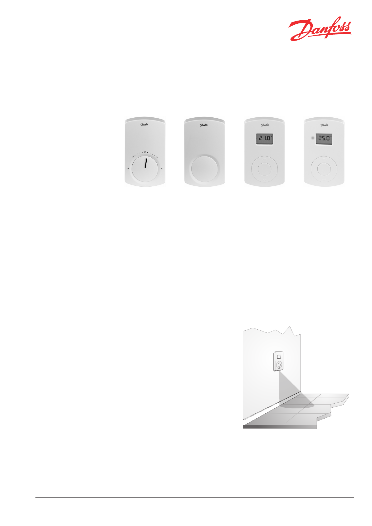
CF-Rx Room Thermostats
Application
CF-RS CF-RP CF-RD CF-RF
CF-Rx is a range of room thermostats for Danfoss'
CF2+ wireless floor heating control system.
CF-Rx thermostats communicate with the CF-MC
Master Controller via 2-way wireless transmission.
All thermostats includes a Link Test function for
easy status indication of the wireless signal and a
LED warning for low battery.
The room thermostats are available in 4 versions.
CF-RS Standard Thermostat:
Easy wireless assignment with Link Test to
▪
Master Controller CF-MC.
Min. and max. limitation of temperature
▪
settings.
Powered by 2 x AA Alkaline 1.5V batteries.
▪
LED indication for low battery.
▪
CF-RP Public (tamperproof) Thermostat:
Easy wireless assignment with Link Test to
▪
Master Controller CF-MC.
Min. and max. limitation of temperature
▪
settings.
Powered by 2 x AA Alkaline 1.5V batteries.
▪
LED indication for low battery.
▪
Hidden set point adjustment for use in
▪
childrens rooms, schools, office buildings
etc.
CF-RD Display Thermostat:
Easy wireless assignment with Link Test to
▪
Master Controller CF-MC.
Min. and max. limitation of temperature
▪
settings.
Powered by 2 x AA Alkaline 1.5V batteries.
▪
LED indication for low battery.
▪
Digital display showing actual or set room
▪
temperature.
CF-RF Display Thermostat with InfraRed floor
sensor:
Easy wireless assignment with Link Test to
▪
Master Controller CF-MC.
Min. and max. limitation of temperature
▪
settings.
Powered by 2 x AA Alkaline 1.5V batteries.
▪
LED indication for low battery.
▪
Digital display showing actual or set room
▪
temperature.
InfraRed floor sensor for minimum and
▪
maximum floor surface temperature
limitation.
Danfoss Heating Solutions VDSPL102 © Danfoss 07/2011 1
Page 4

66 21
111
Data Sheet CF-Rx Room Thermostats
Ordering
Technical data
Product Type Code no.
Standard room thermostat CF-RS 088U0210
Public (tamperproof) room thermostat CF-RP 088U0211
Room thermostat with digital display CF-RD 088U0214
Room thermostat with digital display and InfraRed floor sensor CF-RF 088U0215
Supply voltage 2 x 1.5 Alkaline batteries AA
Battery life CF-RS & CF-RP: 3-4 years
CF-RD & CF-RF: 1-3 years
Transmission frequency 868.42 MHz
Transmission range up to 30 m (in normal buildings)
Transmission power < 1 mW
Temperature setting range 5-35°C
Approvals CE
Standard EN 60730
Directives R&TTE, EMC
Protection class IP21
Weight 120 g
Dimensions
Danfoss A/S
Heating Solutions
Haarupvaenget 11
8600 Silkeborg
Denmark
Phone:+45 7488 8000
Fax: +45 7488 8100
Email: heating.solutions@danfoss.com
www.heating.danfoss.com
Danfoss can accept no responsibility for possible errors in catalogues, brochures and other printed material. Danfoss reserves the right to alter its products without notice. This also applies to products
already on order provided that such alterations can be made without subsequential changes being necessary in specifications already agreed. All trademarks in this material are property of the respective
companies. Danfoss and the Danfoss logotype are trademarks of Danfoss A/S. All rights reserved.
2 VDSPL102 © Danfoss 07/2011 Danfoss Heating Solutions
Page 5

Data Sheet
CF-RC Remote Controller
Application
CF-RC is an optional wireless Remote Controller
for Danfoss' CF2+ wireless floor heating control
system.
CF-RC offers a wide range of extended
functionality and application features:
Wall mounting (in docking station) with
▪
230V supply. If temporarily carried around
powered by 2 x 1.5V Alkaline AA batteries
Low battery indication via icon in display
▪
Display with backlight (initiates when a
▪
button is activated)
2-way wireless transmission with Link Test
▪
possibility
Easy wireless assignment to Master
▪
Controller CF-MC
Error identification and alarm logging
▪
Override and locking of local room
▪
temperature settings
Setback and period programming
▪
System status etc.
▪
Forecast
▪
Low energy optimizer
▪
Control of cooling applications
▪
All CF-RC options and functions are available
through display and push buttons. The menu
structure is self-guiding to make system access
easy.
Larger CF2+ systems can consist of 2 or 3 CF-MC
Master Controllers with up to 30 outputs. For
systems with more Master Controllers, CF-RC
Remote Controller gives access to individual
remote control and settings of each CF-MC
outputs and associated room thermostats.
Ordering
Technical data
Product Type Code no.
CF-RC wireless remote controller CF-RC 088U0221
Supply voltage 230 VAC (docking station) / 2 x 1.5 V Alkaline batteries AA
Transmission frequency 868.42 MHz
Transmission range up to 30 m (in normal buildings)
Transmission power < 1 mW
Approvals CE
Standard EN 60730
Directives R&TTE, LVD, EMC
Protection class IP21
Length of mains cable 1.8 m
Weight 200 g
Danfoss Heating Solutions VDSPM102 © Danfoss 07/2011 1
Page 6

66
23.5
157
Data Sheet CF-RC Remote Controller
Dimensions
Danfoss A/S
Heating Solutions
Haarupvaenget 11
8600 Silkeborg
Denmark
Phone:+45 7488 8000
Fax: +45 7488 8100
Email: heating.solutions@danfoss.com
www.heating.danfoss.com
Danfoss can accept no responsibility for possible errors in catalogues, brochures and other printed material. Danfoss reserves the right to alter its products without notice. This also applies to products
already on order provided that such alterations can be made without subsequential changes being necessary in specifications already agreed. All trademarks in this material are property of the respective
companies. Danfoss and the Danfoss logotype are trademarks of Danfoss A/S. All rights reserved.
2 VDSPM102 © Danfoss 07/2011 Danfoss Heating Solutions
Page 7

Data Sheet
CF-DS Dew Point Sensor
Application
Ordering
Technical data
The CF-DS dew point sensor is used in floor
heating/cooling systems to protect against
building of condensation.
The CF-DS is strapped onto the supply pipe and
connected to the Global Standby input on the
CF-MC Master Controller.
CF-DS measures the relative air humidity
compared to the pipe temperature. At 90% RH
the dew point sensor sends a signal to the CF-MC
Master Controller, which closes the cooling
supply pipes.
Product Code no.
CF-DS dew point sensor 088U0251
Humidity sensor HC 105
Working range 10 - 100% RH
Switching point at 20°C / 68°F 90±3% RH
Switching hysteresis 5% RH
Response time, change of surface temperature
Response time, change of relative humidity
Electrical output potentialfree relay with changeover contact
Switching capacity max. 24 V AC/DC, 1 A
Supply voltage 24 V AC/DC ± 20%
Current consumption at 24 V DC < 3 mA
Relay status indication LED (red)
Electrical connection 5-pole push-in terminal, max. 1.5 mm²
Dust protection by special coating (permeable for water vapour)
Housing protection class IP40
Housing material PC, fire resistant (according to UL94-V0)
Electromagnetic compatibility EN 61326-1, EN 61326-2-3
Working temperature 0 - 50°C / 32 - 122°F
Storage temperature -20 - 70°C / -4 - 158°F
Size (L x H x W) 63 x 54 x 23 mm
Weight approx. 60 g
t90 < 3 min.
t90 < 25 sec.
Danfoss Heating Solutions VDSPI102 © Danfoss 06/2011 1
Page 8

max. Ø 50mm (2“)
NO
NC
COM
GND
V+
24V AC/DC ±20%
Data Sheet CF-DS Dew Point Sensor
Mounting
Heat-conductive film
Wiring Connections
Status indication:
LED continuous light: Operating < 90% RH
▪
LED blinking: Condensation danger
▪
Danfoss A/S
Heating Solutions
Haarupvaenget 11
8600 Silkeborg
Denmark
Phone:+45 7488 8000
Fax: +45 7488 8100
Email: heating.solutions@danfoss.com
www.heating.danfoss.com
Danfoss can accept no responsibility for possible errors in catalogues, brochures and other printed material. Danfoss reserves the right to alter its products without notice. This also applies to products
already on order provided that such alterations can be made without subsequential changes being necessary in specifications already agreed. All trademarks in this material are property of the respective
companies. Danfoss and the Danfoss logotype are trademarks of Danfoss A/S. All rights reserved.
2 VDSPI102 © Danfoss 06/2011 Danfoss Heating Solutions
Page 9

Data Sheet
CF-WR Wireless Relay
Application
Ordering
Technical data
CF-WR wireless relay is an accessory to the
Danfoss CF2+ wireless floor heating/cooling
control system.
CF-WR is used for controlling a condensing
boiler, chiller or pump, and due to wireless
connection with the CF-MC Master Controller,
installation is easy and highly flexible,
Configuration of CF-WR Wireless Relay is made
with the CF-RC Remote Controller. Please refer to
the instruction for CF-RC for further information.
1. PROG button with PROG LED.
2. Button not used for CF2+.
Product Code no.
CF-WR wireless relay 088U0252
Supply voltage 230 Vac ± 15%, 50 Hz
Construction EN 60730-1, EN 300-220-1
Max. ambient temperature 45°C
Switch type RZ1 - 1 x SPDT, type 1B
Switch rating 264 VAC, 3 (1) A
IP class IP 40
Control pollution situation Degree 2
Max. range 30 m
Operating frequency 868.42 MHz
Software classification Class A
Rated impulse voltage 2.5 kV
Ball pressure test 75°C
Size (L x H x W) 83 x 83 x 31 mm
Danfoss Heating Solutions VDSPJ102 © Danfoss 06/2011 1
Page 10

N L 1 2 3 4
Data Sheet CF-WR Wireless Relay
Wiring Connections
Electronics
N
L
1 Not in use
2 Com
3 Zone 1 on
4 Zone 1 off
Note: For mains voltage applications link terminals L and 2.
Danfoss A/S
Heating Solutions
Haarupvaenget 11
8600 Silkeborg
Denmark
Phone:+45 7488 8000
Fax: +45 7488 8100
Email: heating.solutions@danfoss.com
www.heating.danfoss.com
Danfoss can accept no responsibility for possible errors in catalogues, brochures and other printed material. Danfoss reserves the right to alter its products without notice. This also applies to products
already on order provided that such alterations can be made without subsequential changes being necessary in specifications already agreed. All trademarks in this material are property of the respective
companies. Danfoss and the Danfoss logotype are trademarks of Danfoss A/S. All rights reserved.
2 VDSPJ102 © Danfoss 06/2011 Danfoss Heating Solutions
 Loading...