

Page 1
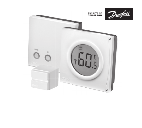
CET2000B-RF + RX1-S + CS2
Wireless Electronic Hot Water Cylinder Thermostat
Danfoss Heating
Installation Guide
Page 2
For a large print version of these instructions
please call Marketing on 0845 121 7400.
Hearby, Danfoss A/S declares that the radio equipment type CET2000B-RF + RX1-S is in
compliance with directive 2014/53/EU.
The full text of the EU declaration of conformity is available at the following internet
address, http://heating.danfoss.co.uk/xdoccat/14_CATC-J_MNU17497125_SIT313.html
Danfoss can accept no responsibility for possible errors in catalogues, brochures, and other
printed material. All trademarks in this material are property of the respective companies.
Danfoss and the Danfoss logotype are trademarks of Danfoss A/S. All rights reserved.
2
CET2000BRF
Page 3
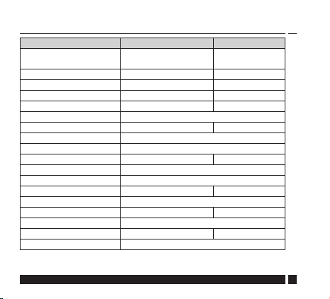
Product Specications
CET2000B-RF RX1-S
Operating Voltage
Output Relay - 1 x SPDT Type 1B
Switch rating - 3A (1) at 230Vac
Output - Volt free
Setting temp. range 40-65°C Maximum ambient temp. 0-45°C
Battery lifetime 2 years Max. range 30 metres
Operating frequency 433.92MHz <1mW ERP
IP Rating IP20 IP40
Control On-O
Operating mode Domestic Hot Water Heating
Construction EN 60730-2-9 EN 60730-1
Control pollution situation Degree 2
Rated impulse voltage - 2.5kV
Ball pressure test 75°C
Dimensions H84 x W84 x D35 H84 x W84 x D28
Software classication A
Important note RF products: Ensure that there are no large metal objects, such as
boiler cases or other large appliances, in line of sight between the transmitter and
receiver as these will prevent communication between thermostat and receiver.
Danfoss Heating
2.5 – 3 VDC
(2xAA alkaline batteries)
230Vac 50Hz
3
Page 4
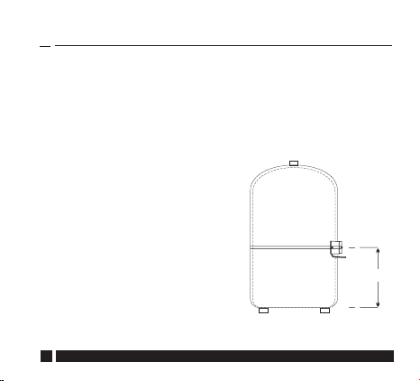
ylinder
For insulation thicker than 25mm
and up to 55mm thick, use the
extra cover supplied as a spacer to
ensure that the sensor is held in
firm contact with the cylinder wall.
Installation
This product should only be installed by a qualied
electrician or competent heating installer, and must be
in accordance with local wiring regulations.
!
1. The clamp on sensor should
be mounted onto the
cylinder wall at a height
equivalent to ½ the height
of the cylinder. Care should
be taken to remove any
insulation material from
the cylinder and to ensure
that the copper surface of
the cylinder is clean. See
diagram opposite for details.
4
CET2000B-RF
1/2 c
height
Page 5

2. Before attaching the sensor to the cylinder using the strap
provided, connect a 2-core cable to the sensor to allow
interconnection to the thermostat setting unit.
3. Apply the contact paste provided to the part of the sensor
in contact with the cylinder and clamp the sensor to the
cylinder wall.
A spacer piece is provided for use with cylinders that have
thick insulation (see page 6).
4. Mount the thermostat wallplate on to a wall next to the
cylinder. Connect the cable from the sensor to terminals 1
& 2 of the wallplate (see wiring diagram on page 7).
5. Now mount the thermostat setting unit onto the wallplate
(see diagrams on page 9).
Danfoss Heating
5
Page 6

For insulation thicker than 25mm
and up to 55mm thick, use the
extra cover supplied as a spacer to
ensure that the sensor is held in
rm contact with the cylinder wall.
6
CET2000B-RF
Page 7

Sensor Wiring
CET2000B-RF
1 2 3
CS2
sensor
Cable specication: minimum cross section 0.5mm
Danfoss Heating
2
7
Page 8

Installation - RX1-S Receiver unit
ELECTRONICS
N
L
N
L
2
3
4
COM
ON
OFF
230Vac
1
Please Note: This product should only be installed by a
qualied electrician or competent heating installer, and must
be in accordance with local wiring regulations.
8
CET2000B-RF
Page 9

Mounting - CET2000B-RF
Danfoss Heating
9
Page 10

Hard Wired Heating with Wireless Hot Water
Control, 3 Port Mid-Position Valve
10
FP715 Programmer
FP715 Programmer
ELECTRONICS
N
L
230Vac
RX1-S Receiver -
paired to CET2000B-RF
RET1000MS
Room Thermostat
N
4
3
1
2
HTG ON
HW ON
HTG OFF
HW OFF
L
N L
Pump
ELECTRONICS
2
N
N L
Boiler
L
SW.L
3 Port Mid-Position Valve
3
2
1
blue
grey
brown/
white
orange
CET2000B-RF
Page 11

Wireless Heating and Hot Water Control,
Heating 2 Port Valve
using 2 x 2 Port Valves
FP715 Programmer
FP715 Programmer
ELECTRONICS
N
L
1
HTG OFF
HW OFF
230Vac
N L
Pump
Danfoss Heating
3
RX1-S Receiver -
paired to CET2000B-RF
ELECTRONICS
N
L
grey
orange
Hot Water 2 Port Valve
3
2
1
blue
brown
RX1-S Receiver -
paired to RET2000B-RF
ELECTRONICS
4
3
2
HW ON
N L
Boiler
N
L
HTG ON
Sw.L
2
1
grey
blue
brown
orange
11
Page 12

Hard Wired Heating with Wireless Hot Water
Control, 2 x 2 Port Valves
12
FP715 Programmer
FP715 Programmer
ELECTRONICS
N
L
230Vac
N L
Pump
RX1-S Receiver -
paired to CET2000B-RF
2
brown
ELECTRONICS
N
L
grey
orange
Hot Water 2 Port Valve
3
2
1
blue
brown
RET1000MS
Room Thermostat
N
4
3
1
2
HTG ON
HW ON
HTG OFF
HW OFF
Sw.L
N L
Boiler
L
grey
blue
orange
Heating 2 Port Valve
CET2000B-RF
Page 13

Wireless Heating & Hot Water Control, with
3 Port Mid Position Valve
FP715 Programmer
FP715 Programmer
ELECTRONICS
N
L
1
HW OFF
230Vac
Danfoss Heating
HTG OFF
2
N L
Pump
N
3
grey
orange
RX1-S Receiver -
paired to CET2000B-RF
ELECTRONICS
L
1
3
2
RX1-S Receiver -
paired to RET2000B-RF
ELECTRONICS
4
3
N
L
HTG ON
HW ON
Sw.L
N L
Boiler
2
1
blue
brown/
white
3 Port Mid-Position Valve
13
Page 14

Key Lock
Slide the DIL switches
to the settings required.
NOT USED
NOT USED
NOT USED
KEYS UNLOCKED
1
2
3
4
NOT USED
NOT USED
NOT USED
KEYS LOCKED
To avoid unwanted tampering of the required hot water temperature the CET2000B-RF includes a key lock feature which
disables the Λ and V buttons.
First set the required hot water temperature using the Λ or V
button. Then slide internal DIL switch 4 to the locked position and mount the CET2000B-RF back on its wallplate (as
shown on page 9).
14
CET2000B-RF
Page 15

Commissioning
If the thermostat CET2000B-RF and receiver RX1-S have been
supplied together in a combined pack, the units have been
paired in the factory and no commissioning is required. If the
thermostat and receiver have been supplied separately follow
the steps below to pair the devices.
Step 1 RX1-S - Ensure RX1-S is wired in accordance with
instructions on page 8.
Step 2 CET2000B-RF - Insert 2xAA alkaline batteries. If the
CET2000B-RF is not already paired to the RX1-S it will enter it’s
learning mode shown by the ashing aerial icon.
Step 3 RX1-S - Press and hold down both the PROG and CH
buttons. The PROG LED will light for 1 second when it has
paired with the CET2000B-RF. Release buttons
A steady aerial icon on CET2000B-RF conrms that the devices
are now paired and ready for control of your domestic hot water
system.
Danfoss Heating
15
Page 16

Danfoss Ltd
Ampthill Road
Bedford MK42 9ER
Tel: 01234 364621
Fax: 01234 219705
Email: ukheating@danfoss.com
Website: www.heating.danfoss.co.uk
Part No 44101v01 04/15
VIAGD102
 Loading...